Manual
Page 4
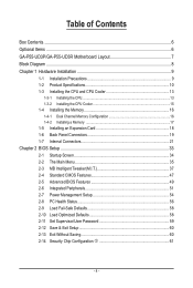
... Items...6 GA-P55-UD3P/GA-P55-UD3R Motherboard Layout 7 Block Diagram...8 Chapter 1 Hardware Installation 9 1-1 Installation Precautions 9 1-2 Product Specifications 10 1-3 Installing the CPU and CPU Cooler 13 1-3-1 Installing the CPU 13 1-3-2 Installing the CPU Cooler 15 1-4 Installing the Memory 16 1-4-1 Dual Channel Memory Configuration 16 1-4-2 Installing a Memory 17 1-5 Installing an Expansion Card 18 1-6 Back Panel Connectors 19...
... Items...6 GA-P55-UD3P/GA-P55-UD3R Motherboard Layout 7 Block Diagram...8 Chapter 1 Hardware Installation 9 1-1 Installation Precautions 9 1-2 Product Specifications 10 1-3 Installing the CPU and CPU Cooler 13 1-3-1 Installing the CPU 13 1-3-2 Installing the CPU Cooler 15 1-4 Installing the Memory 16 1-4-1 Dual Channel Memory Configuration 16 1-4-2 Installing a Memory 17 1-5 Installing an Expansion Card 18 1-6 Back Panel Connectors 19...
Manual
Page 10
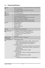
... eSATA 3Gb/s connectors on the back panel supporting up to 2 SATA 3Gb/s devices - 1-2 Product Specifications CPU Support for an Intel® Core™ i7 series processor/Intel® Core™ i5 series processor in the LGA1156 package (Go to GIGABYTE's website for the latest CPU support ...list.) L3 cache varies with CPU Chipset Intel® P55 Express Chipset Memory Audio 4 x 1.5V DDR3 DIMM sockets supporting up to...
... eSATA 3Gb/s connectors on the back panel supporting up to 2 SATA 3Gb/s devices - 1-2 Product Specifications CPU Support for an Intel® Core™ i7 series processor/Intel® Core™ i5 series processor in the LGA1156 package (Go to GIGABYTE's website for the latest CPU support ...list.) L3 cache varies with CPU Chipset Intel® P55 Express Chipset Memory Audio 4 x 1.5V DDR3 DIMM sockets supporting up to...
Manual
Page 11
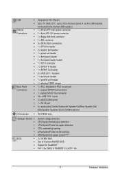
... w w w w w w Integrated in the Chipset Up to 14 USB 2.0/1.1 ports (10 on the back panel, 4 via the USB brackets connected to the internal USB headers) 1 x 24-pin ATX main power connector 1 x 8-pin ATX ...12V power connector 1 x floppy disk drive connector 1 x IDE connector 8 x SATA 3Gb/s connectors 1 x CPU fan header 2 x system fan headers 1 x power fan header 1 x front panel header 1 x front panel audio header 1 x CD In connector 1 x S/PDIF In header 1 x S/PDIF Out header 2 x USB 2.0/1.1 headers 1 x serial port header 1 x parallel port header 1 x clearing ...
... w w w w w w Integrated in the Chipset Up to 14 USB 2.0/1.1 ports (10 on the back panel, 4 via the USB brackets connected to the internal USB headers) 1 x 24-pin ATX main power connector 1 x 8-pin ATX ...12V power connector 1 x floppy disk drive connector 1 x IDE connector 8 x SATA 3Gb/s connectors 1 x CPU fan header 2 x system fan headers 1 x power fan header 1 x front panel header 1 x front panel audio header 1 x CD In connector 1 x S/PDIF In header 1 x S/PDIF Out header 2 x USB 2.0/1.1 headers 1 x serial port header 1 x parallel port header 1 x clearing ...
Manual
Page 18
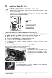
... in your computer. Turn on the card are completely inserted into the PCI Express slot. If necessary, go to BIOS Setup to the chassis back panel with your card. 1-5 Installing an Expansion Card Read the following guidelines before installing an expansion card to install an expansion card: • Make sure the... a screw. 5. Carefully read the manual that supports your expansion card. • Always turn off the computer and unplug the power cord from the chassis back panel. 2. After installing all expansion cards, replace the chassis cover(s). 6.
... in your computer. Turn on the card are completely inserted into the PCI Express slot. If necessary, go to BIOS Setup to the chassis back panel with your card. 1-5 Installing an Expansion Card Read the following guidelines before installing an expansion card to install an expansion card: • Make sure the... a screw. 5. Carefully read the manual that supports your expansion card. • Always turn off the computer and unplug the power cord from the chassis back panel. 2. After installing all expansion cards, replace the chassis cover(s). 6.
Manual
Page 19
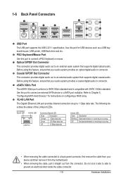
... Description Blinking Data transmission or receiving is occurring Off No data transmission or receiving is compatible with SATA 1.5Gb/s standard. 1-6 Back Panel Connectors USB Port The USB port supports the USB 2.0/1.1 specification. PS/2 Keyboard/Mouse Port Use this feature, ensure that your device and... then remove it from the motherboard. • When removing the cable, pull it side to side to a back panel connector, first remove the cable from the connector. Coaxial S/PDIF Out Connector This connector provides digital audio out to connect a PS/2 keyboard...
... Description Blinking Data transmission or receiving is occurring Off No data transmission or receiving is compatible with SATA 1.5Gb/s standard. 1-6 Back Panel Connectors USB Port The USB port supports the USB 2.0/1.1 specification. PS/2 Keyboard/Mouse Port Use this feature, ensure that your device and... then remove it from the motherboard. • When removing the cable, pull it side to side to a back panel connector, first remove the cable from the connector. Coaxial S/PDIF Out Connector This connector provides digital audio out to connect a PS/2 keyboard...
Manual
Page 26
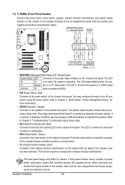
...a beep code. Refer to Chapter 5, "Troubleshooting," for more information). • SPEAK (Speaker, Orange): Connects to the speaker on the chassis front panel. This function requires a chassis with a chassis intrusion switch/sensor. When connecting your system using the power switch (refer to Chapter 2, "BIOS Setup,"...about beep codes. • HD (Hard Drive Activity LED, Blue) Connects to the hard drive activity LED on the chassis front panel. A front panel module mainly consists of power switch, reset switch, power LED, hard drive activity LED, speaker and etc. The LED keeps blinking ...
...a beep code. Refer to Chapter 5, "Troubleshooting," for more information). • SPEAK (Speaker, Orange): Connects to the speaker on the chassis front panel. This function requires a chassis with a chassis intrusion switch/sensor. When connecting your system using the power switch (refer to Chapter 2, "BIOS Setup,"...about beep codes. • HD (Hard Drive Activity LED, Blue) Connects to the hard drive activity LED on the chassis front panel. A front panel module mainly consists of power switch, reset switch, power LED, hard drive activity LED, speaker and etc. The LED keeps blinking ...
Manual
Page 27
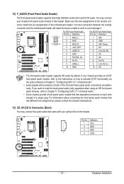
...audio cable that has separated connectors on both of the motherboard header. Definition Pin No. If your chassis provides an AC'97 front panel audio module, refer to the instructions on how to activate AC'97 functionality via the audio software in Chapter 5, "Configuring 2/4/5.1/7.1-Channel ...Audio." • Audio signals will make the device unable to work or even damage it. For information about connecting the front panel audio module that has different wire assignments, please contact the chassis manufacturer. 13) CD_IN (CD In Connector, Black) You may connect your...
...audio cable that has separated connectors on both of the motherboard header. Definition Pin No. If your chassis provides an AC'97 front panel audio module, refer to the instructions on how to activate AC'97 functionality via the audio software in Chapter 5, "Configuring 2/4/5.1/7.1-Channel ...Audio." • Audio signals will make the device unable to work or even damage it. For information about connecting the front panel audio module that has different wire assignments, please contact the chassis manufacturer. 13) CD_IN (CD In Connector, Black) You may connect your...

Manual
Page 109
woofer speaker out jack, you want to mute the back panel audio (only supported when using an HD front panel audio module), refer to the following instructions use Windows Vista as the example operating system.) Step 1: After installing the audio driver, the HD Audio ...speaker out jack to be Rear speaker out. • To install a microphone, connect your microphone to be present on both of the front and back panel audio connections simultaneously. High Definition Audio (HD Audio) HD Audio includes multiple high quality digital-to MP3 music, have an Internet chat, make a telephone ...
woofer speaker out jack, you want to mute the back panel audio (only supported when using an HD front panel audio module), refer to the following instructions use Windows Vista as the example operating system.) Step 1: After installing the audio driver, the HD Audio ...speaker out jack to be Rear speaker out. • To install a microphone, connect your microphone to be present on both of the front and back panel audio connections simultaneously. High Definition Audio (HD Audio) HD Audio includes multiple high quality digital-to MP3 music, have an Internet chat, make a telephone ...

Manual
Page 110
... environment on the Speaker Configuration tab. The The current connected device is completed. Activating an AC'97 Front Panel Audio Module If your chassis provides an AC'97 front panel audio module, to activate the AC'97 functionality, click the tool icon on the Sound Effects tab. Step... 3: On the Speakers screen, click the Speaker Configuration tab. C. Muting the Back Panel Audio (For HD Audio Only) Click Device advanced settings on the top right corner on the Speaker Configuration tab to set up. B. Appendix - 110...
... environment on the Speaker Configuration tab. The The current connected device is completed. Activating an AC'97 Front Panel Audio Module If your chassis provides an AC'97 front panel audio module, to activate the AC'97 functionality, click the tool icon on the Sound Effects tab. Step... 3: On the Speakers screen, click the Speaker Configuration tab. C. Muting the Back Panel Audio (For HD Audio Only) Click Device advanced settings on the top right corner on the Speaker Configuration tab to set up. B. Appendix - 110...

Manual
Page 111
... metal bracket to select the default format. Appendix Configuring S/PDIF In: On the Digital Input screen, click the Default Format tab to the chassis back panel with a screw. 2. Click OK to complete. (Note) The actual locations of the cable to the computer for audio processing. Installing the S/PDIF In Cable: Step...
... metal bracket to select the default format. Appendix Configuring S/PDIF In: On the Digital Input screen, click the Default Format tab to the chassis back panel with a screw. 2. Click OK to complete. (Note) The actual locations of the cable to the computer for audio processing. Installing the S/PDIF In Cable: Step...

Manual
Page 113
...for microphone functionality. Step 2: Connect your microphone to the Mic in jack (pink) on the back panel or the Mic in the notification area. Note: The microphone functions on the front panel and back panel cannot be able to microphone, right-click on Microphone and select Set Default Device. - 113 - To... level. 5-2-3 Configuring Microphone Recording Step 1: After installing the audio driver, the HD Audio Manager icon will appear in jack (pink) on the front panel. Do not mute the recording volume, or you want to change the current sound input default device to record the sound.
...for microphone functionality. Step 2: Connect your microphone to the Mic in jack (pink) on the back panel or the Mic in the notification area. Note: The microphone functions on the front panel and back panel cannot be able to microphone, right-click on Microphone and select Set Default Device. - 113 - To... level. 5-2-3 Configuring Microphone Recording Step 1: After installing the audio driver, the HD Audio Manager icon will appear in jack (pink) on the front panel. Do not mute the recording volume, or you want to change the current sound input default device to record the sound.


