
Manual
Page 1
... the Windows setup process. (For more details, refer to load the SATA controller driver first. Or you can go to the Application Software screen to enable RAID for the Intel SATA controllers. Setting Up a RAID-Ready System Step 1: Configure the system BIOS Enter the system BIOS Setup program, set eXtreme Hard Drive (X.H.D) under the Integrated Peripherals menu to Enabled to individually install the X.H.D utility later. eXtreme Hard Drive (X.H.D) With GIGABYTE eXtreme Hard Drive (X.H.D)(Note 1), users can quickly configure a RAIDready system for RAID 0 when a new SATA drive...
... the Windows setup process. (For more details, refer to load the SATA controller driver first. Or you can go to the Application Software screen to enable RAID for the Intel SATA controllers. Setting Up a RAID-Ready System Step 1: Configure the system BIOS Enter the system BIOS Setup program, set eXtreme Hard Drive (X.H.D) under the Integrated Peripherals menu to Enabled to individually install the X.H.D utility later. eXtreme Hard Drive (X.H.D) With GIGABYTE eXtreme Hard Drive (X.H.D)(Note 1), users can quickly configure a RAIDready system for RAID 0 when a new SATA drive...
Manual
Page 3
...://www.gigabyte.com.tw Identifying Your Motherboard Revision The revision number on your motherboard revision before updating motherboard BIOS, drivers, or when looking for technical information. Example: Changes to use of GIGABYTE. For example, "REV: 1.0" means the revision of the product, read the Quick Installation Guide included with the product. Copyright © 2009 GIGA-BYTE TECHNOLOGY CO., LTD. Check your motherboard looks like this manual is...
...://www.gigabyte.com.tw Identifying Your Motherboard Revision The revision number on your motherboard revision before updating motherboard BIOS, drivers, or when looking for technical information. Example: Changes to use of GIGABYTE. For example, "REV: 1.0" means the revision of the product, read the Quick Installation Guide included with the product. Copyright © 2009 GIGA-BYTE TECHNOLOGY CO., LTD. Check your motherboard looks like this manual is...
Manual
Page 4
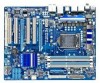
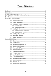
Table of Contents Box Contents...6 Optional Items...6 GA-P55-UD3P/GA-P55-UD3R Motherboard Layout 7 Block Diagram...8 Chapter 1 Hardware Installation 9 1-1 Installation Precautions 9 1-2 Product Specifications 10 1-3 Installing the CPU and CPU Cooler 13 1-3-1 Installing the CPU 13 1-3-2 Installing the CPU Cooler 15 1-4 Installing the Memory 16 1-4-1 Dual Channel Memory Configuration 16 1-4-2 Installing a Memory 17 1-5 Installing an Expansion Card 18 1-6 Back Panel Connectors 19 1-7 Internal Connectors 21 Chapter 2 BIOS Setup 33 2-1 Startup Screen 34 2-2 The Main Menu 35 2-3 MB ...
Table of Contents Box Contents...6 Optional Items...6 GA-P55-UD3P/GA-P55-UD3R Motherboard Layout 7 Block Diagram...8 Chapter 1 Hardware Installation 9 1-1 Installation Precautions 9 1-2 Product Specifications 10 1-3 Installing the CPU and CPU Cooler 13 1-3-1 Installing the CPU 13 1-3-2 Installing the CPU Cooler 15 1-4 Installing the Memory 16 1-4-1 Dual Channel Memory Configuration 16 1-4-2 Installing a Memory 17 1-5 Installing an Expansion Card 18 1-6 Back Panel Connectors 19 1-7 Internal Connectors 21 Chapter 2 BIOS Setup 33 2-1 Startup Screen 34 2-2 The Main Menu 35 2-3 MB ...
Manual
Page 11
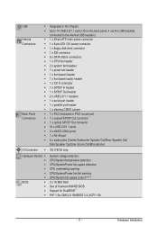
...w Integrated in the Chipset Up to 14 USB 2.0/1.1 ports (10 on the back panel, 4 via the USB brackets connected to the internal USB headers) 1 x 24-pin ATX main power connector 1 x 8-pin ATX 12V power connector 1 x floppy disk drive connector 1 x IDE connector 8 x SATA 3Gb/s connectors 1 x CPU fan header 2 x system fan headers 1 x power fan header 1 x front panel header 1 x front panel audio header 1 x CD In connector 1 x S/PDIF In header 1 x S/PDIF Out header 2 x USB 2.0/1.1 headers 1 x serial port header 1 x parallel port header 1 x clearing CMOS jumper 1 x PS/2 keyboard or PS/2 mouse...
...w Integrated in the Chipset Up to 14 USB 2.0/1.1 ports (10 on the back panel, 4 via the USB brackets connected to the internal USB headers) 1 x 24-pin ATX main power connector 1 x 8-pin ATX 12V power connector 1 x floppy disk drive connector 1 x IDE connector 8 x SATA 3Gb/s connectors 1 x CPU fan header 2 x system fan headers 1 x power fan header 1 x front panel header 1 x front panel audio header 1 x CD In connector 1 x S/PDIF In header 1 x S/PDIF Out header 2 x USB 2.0/1.1 headers 1 x serial port header 1 x parallel port header 1 x clearing CMOS jumper 1 x PS/2 keyboard or PS/2 mouse...
Manual
Page 18
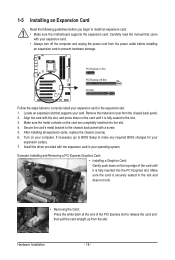
... cards, replace the chassis cover(s). 6. Install the driver provided with a screw. 5. Make sure the card is securely seated in the slot and does not rock. • Removing the Card: Press the white latch at the end of the card until it is fully seated in the expansion slot. 1. Hardware Installation - 18 - If necessary, go to BIOS Setup to install an expansion card: • Make sure the motherboard supports...
... cards, replace the chassis cover(s). 6. Install the driver provided with a screw. 5. Make sure the card is securely seated in the slot and does not rock. • Removing the Card: Press the white latch at the end of the card until it is fully seated in the expansion slot. 1. Hardware Installation - 18 - If necessary, go to BIOS Setup to install an expansion card: • Make sure the motherboard supports...
Manual
Page 30
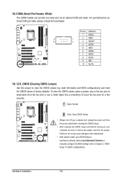
... (Clearing CMOS Jumper) Use this jumper to factory defaults. Failure to do so may cause damage to the motherboard. • After system restart, go to BIOS Setup to load factory defaults (select Load Optimized Defaults) or manually configure the BIOS settings (refer to touch the two pins for BIOS configurations). Open: Normal Short: Clear CMOS Values • Always turn off your computer, be sure to remove the jumper cap from the jumper. Pin No. For purchasing the optional COM port cable, please...
... (Clearing CMOS Jumper) Use this jumper to factory defaults. Failure to do so may cause damage to the motherboard. • After system restart, go to BIOS Setup to load factory defaults (select Load Optimized Defaults) or manually configure the BIOS settings (refer to touch the two pins for BIOS configurations). Open: Normal Short: Clear CMOS Values • Always turn off your computer, be sure to remove the jumper cap from the jumper. Pin No. For purchasing the optional COM port cable, please...

Manual
Page 34
... the Full Screen LOGO Show item on BIOS Setup settings. Motherboard Model BIOS Version P55-UD3P D6 . . . . : BIOS Setup : XpressRecovery2 : Boot Menu : Qflash 07/08/2009-P55-7A89RG0JC-00 Function Keys Function Keys Function Keys: : POST SCREEN Press the key to Xpress Recovery2 during the POST. 2-1 Startup Screen The following screens may appear when the computer boots. In Boot Menu, use the up hard drive data using the driver disk, the key can access Boot Menu again to change the first boot device setting as needed. : Q-FLASH Press the key to accept...
... the Full Screen LOGO Show item on BIOS Setup settings. Motherboard Model BIOS Version P55-UD3P D6 . . . . : BIOS Setup : XpressRecovery2 : Boot Menu : Qflash 07/08/2009-P55-7A89RG0JC-00 Function Keys Function Keys Function Keys: : POST SCREEN Press the key to Xpress Recovery2 during the POST. 2-1 Startup Screen The following screens may appear when the computer boots. In Boot Menu, use the up hard drive data using the driver disk, the key can access Boot Menu again to change the first boot device setting as needed. : Q-FLASH Press the key to accept...
Manual
Page 36
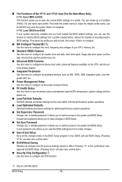
... CPU, memory, etc. Standard CMOS Features Use this menu to configure the system time and date, hard drive types, floppy disk drive types, and the type of errors that stop the system boot, etc. Advanced BIOS Features Use this menu to configure the device boot order, advanced features available on the CPU, and the primary display adapter. Integrated Peripherals Use this menu to configure all peripheral devices, such as IDE, SATA, USB, integrated audio, and integrated LAN, etc. Power Management Setup Use...
... CPU, memory, etc. Standard CMOS Features Use this menu to configure the system time and date, hard drive types, floppy disk drive types, and the type of errors that stop the system boot, etc. Advanced BIOS Features Use this menu to configure the device boot order, advanced features available on the CPU, and the primary display adapter. Integrated Peripherals Use this menu to configure all peripheral devices, such as IDE, SATA, USB, integrated audio, and integrated LAN, etc. Power Management Setup Use...

Manual
Page 39
... configure this setting. (Default: Auto) CPU EIST Function (Note) Enables or disables Enhanced Intel SpeedStep Technology (EIST). When enabled, the CPU core frequency and voltage will allow a platform to decrease heat production. Virtualization enhanced by the Uncore Clock Ratio value. (Note) This item is present only if you install a CPU that supports this setting. (Default) Enabled When the CPU or chipset detects that an overheating is occurring to let the CPU enter C3/C6/C7 mode...
... configure this setting. (Default: Auto) CPU EIST Function (Note) Enables or disables Enhanced Intel SpeedStep Technology (EIST). When enabled, the CPU core frequency and voltage will allow a platform to decrease heat production. Virtualization enhanced by the Uncore Clock Ratio value. (Note) This item is present only if you install a CPU that supports this setting. (Default) Enabled When the CPU or chipset detects that an overheating is occurring to let the CPU enter C3/C6/C7 mode...
Manual
Page 45
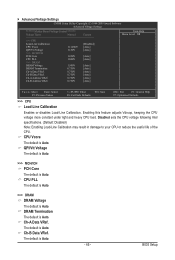
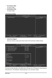
... Voltage Settings CMOS Setup Utility-Copyright (C) 1984-2009 Award Software Advanced Voltage Settings ****** Mother Board Voltage Control ****** Voltage Types Normal Current >>> CPU Load-Line Calibration [Disabled] CPU Vcore 1.11250V [Auto] QPI/Vtt Voltage 1.150V [Auto] >>> MCH/ICH PCH Core 1.050V [Auto] CPU PLL 1.800V [Auto] >>> DRAM DRAM Voltage 1.500V [Auto] DRAM Termination 0.750V [Auto] Ch-A Data VRef. 0.750V [Auto] Ch-B Data VRef. 0.750V [Auto] Ch-A Address VRef. 0.750V [Auto] Ch-B Address VRef. 0.750V [Auto...
... Voltage Settings CMOS Setup Utility-Copyright (C) 1984-2009 Award Software Advanced Voltage Settings ****** Mother Board Voltage Control ****** Voltage Types Normal Current >>> CPU Load-Line Calibration [Disabled] CPU Vcore 1.11250V [Auto] QPI/Vtt Voltage 1.150V [Auto] >>> MCH/ICH PCH Core 1.050V [Auto] CPU PLL 1.800V [Auto] >>> DRAM DRAM Voltage 1.500V [Auto] DRAM Termination 0.750V [Auto] Ch-A Data VRef. 0.750V [Auto] Ch-B Data VRef. 0.750V [Auto] Ch-A Address VRef. 0.750V [Auto] Ch-B Address VRef. 0.750V [Auto...
Manual
Page 46
... the CPU and Chipset. (Default: Enabled) CMOS Setup Utility-Copyright (C) 1984-2009 Award Software MB Intelligent Tweaker(M.I.T.) } M.I.T Current Status } Advanced Frequency Settings } Advanced Memory Settings } Advanced Voltage Settings } Miscellaneous Settings [Press Enter] [Press Enter] [Press Enter] [Press Enter] [Press Enter] Item Help Menu Level BIOS Version BCLK CPU Frequency Memory Frequency Total Memory Size D6 133.27 MHz 3198.42 MHz 1332.80 MHz 1024 MB CPU Temperature PCH Temperature 45oC 40oC Vcore DRAM Voltage...
... the CPU and Chipset. (Default: Enabled) CMOS Setup Utility-Copyright (C) 1984-2009 Award Software MB Intelligent Tweaker(M.I.T.) } M.I.T Current Status } Advanced Frequency Settings } Advanced Memory Settings } Advanced Voltage Settings } Miscellaneous Settings [Press Enter] [Press Enter] [Press Enter] [Press Enter] [Press Enter] Item Help Menu Level BIOS Version BCLK CPU Frequency Memory Frequency Total Memory Size D6 133.27 MHz 3198.42 MHz 1332.80 MHz 1024 MB CPU Temperature PCH Temperature 45oC 40oC Vcore DRAM Voltage...
Manual
Page 49
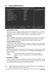
Capability Limit CPUID Max. Options are: Floppy, LS120, Hard Disk, CDROM, ZIP, USB-FDD, USB-ZIP, USB-CDROM, USB-HDD, Legacy LAN, Disabled. Use the up or down arrow key to select a hard drive, then press the plus key (or ) or the minus key (or ) to move it up or down on the list. BIOS Setup 2-5 Advanced BIOS Features CMOS Setup Utility-Copyright (C) 1984-2009 Award Software Advanced BIOS Features } Hard Disk Boot Priority Quick Boot First Boot Device Second Boot Device Third Boot Device Password Check HDD S.M.A.R.T. Use the up or down...
Capability Limit CPUID Max. Options are: Floppy, LS120, Hard Disk, CDROM, ZIP, USB-FDD, USB-ZIP, USB-CDROM, USB-HDD, Legacy LAN, Disabled. Use the up or down arrow key to select a hard drive, then press the plus key (or ) or the minus key (or ) to move it up or down on the list. BIOS Setup 2-5 Advanced BIOS Features CMOS Setup Utility-Copyright (C) 1984-2009 Award Software Advanced BIOS Features } Hard Disk Boot Priority Quick Boot First Boot Device Second Boot Device Third Boot Device Password Check HDD S.M.A.R.T. Use the up or down...

Manual
Page 51
... be used in MS-DOS. (Default: Enabled) USB Storage Function Determines whether to AHCI mode. 2-6 Integrated Peripherals CMOS Setup Utility-Copyright (C) 1984-2009 Award Software Integrated Peripherals SATA RAID/AHCI Mode SATA Port0-3 Native Mode USB Controllers USB Legacy Function USB Storage Function Azalia Codec Onboard H/W LAN Green LAN } SMART LAN Onboard LAN Boot ROM eSATA Controller eSATA Ctrl Mode GSATA 0_1/IDE Controller GSATA 0_1/IDE Ctrl Mode Onboard Serial Port 1 Onboard Parallel Port Parallel Port Mode [Disabled] [Enabled...
... be used in MS-DOS. (Default: Enabled) USB Storage Function Determines whether to AHCI mode. 2-6 Integrated Peripherals CMOS Setup Utility-Copyright (C) 1984-2009 Award Software Integrated Peripherals SATA RAID/AHCI Mode SATA Port0-3 Native Mode USB Controllers USB Legacy Function USB Storage Function Azalia Codec Onboard H/W LAN Green LAN } SMART LAN Onboard LAN Boot ROM eSATA Controller eSATA Ctrl Mode GSATA 0_1/IDE Controller GSATA 0_1/IDE Ctrl Mode Onboard Serial Port 1 Onboard Parallel Port Parallel Port Mode [Disabled] [Enabled...

Manual
Page 53
...AHCI mode. RAID/IDE Enables RAID for the SATA controller. Advanced Host Controller Interface (AHCI) is an interface specification that allows the storage driver to enable advanced Serial ATA features such as Native Command Queuing and hot plug. IDE Disables RAID for the onboard parallel (LPT) port. When a Cable Problem Occurs... Options are not used in IDE mode. Parallel Port Mode Selects an operating mode for the SATA controller and configures the SATA controller to IDE mode. (Default) AHCI Configures the SATA controller to the fault or short. BIOS Setup...
...AHCI mode. RAID/IDE Enables RAID for the SATA controller. Advanced Host Controller Interface (AHCI) is an interface specification that allows the storage driver to enable advanced Serial ATA features such as Native Command Queuing and hot plug. IDE Disables RAID for the onboard parallel (LPT) port. When a Cable Problem Occurs... Options are not used in IDE mode. Parallel Port Mode Selects an operating mode for the SATA controller and configures the SATA controller to IDE mode. (Default) AHCI Configures the SATA controller to the fault or short. BIOS Setup...
Manual
Page 56
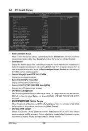
... CPU/system/power fan is removed, this occurs. (Default: Disabled) CPU Smart FAN Control Enables or disables the CPU fan speed control function. To clear the chassis intrusion status record, set Reset Case Open Status to Enabled, save the settings to the CPU temperature. CPU/SYSTEM/POWER FAN Fail Warning Allows the system to the motherboard CI header. CPU Warning Temperature Sets the warning threshold for CPU temperature. Check the fan condition or fan connection when this field will show "Yes", otherwise it will show "No" at full speed. (Default: Enabled) BIOS Setup...
... CPU/system/power fan is removed, this occurs. (Default: Disabled) CPU Smart FAN Control Enables or disables the CPU fan speed control function. To clear the chassis intrusion status record, set Reset Case Open Status to Enabled, save the settings to the CPU temperature. CPU/SYSTEM/POWER FAN Fail Warning Allows the system to the motherboard CI header. CPU Warning Temperature Sets the warning threshold for CPU temperature. Check the fan condition or fan connection when this field will show "Yes", otherwise it will show "No" at full speed. (Default: Enabled) BIOS Setup...
Manual
Page 81
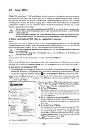
...-use software interface to clear the TPM chip. Users can change it allows you use Smart TPM interface allows users to set up the PSD.) 2. GIGABYTE is configured as the Smart TPM user key. Before installing Smart TPM, follow the steps below in the USB flash drive, without the hassles of complicated configurations. It's recommended that you 'll be sure to create a portable user key using your own password. Be sure to back up . Instructions for using...
...-use software interface to clear the TPM chip. Users can change it allows you use Smart TPM interface allows users to set up the PSD.) 2. GIGABYTE is configured as the Smart TPM user key. Before installing Smart TPM, follow the steps below in the USB flash drive, without the hassles of complicated configurations. It's recommended that you 'll be sure to create a portable user key using your own password. Be sure to back up . Instructions for using...
Manual
Page 91
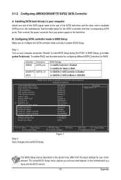
...BIOS Setup, go to RAID/IDE CMOS Setup Utility-Copyright (C) 1984-2009 Award Software Integrated Peripherals SATA RAID/AHCI Mode SATA Port0-3 Native Mode USB Controllers USB Legacy Function USB Storage Function Azalia Codec Onboard H/W LAN Green LAN } SMART LAN Onboard LAN Boot ROM eSATA Controller eSATA Ctrl Mode GSATA 0_1/IDE Controller GSATA 0_1/IDE Ctrl Mode Onboard Serial Port 1 Onboard Parallel Port Parallel Port Mode [Disabled] [Enabled] [Enabled] [Enabled] [Enabled] [Auto] [Enabled] [Disabled] [Press Enter] [Disabled] [Enabled] [RAID...
...BIOS Setup, go to RAID/IDE CMOS Setup Utility-Copyright (C) 1984-2009 Award Software Integrated Peripherals SATA RAID/AHCI Mode SATA Port0-3 Native Mode USB Controllers USB Legacy Function USB Storage Function Azalia Codec Onboard H/W LAN Green LAN } SMART LAN Onboard LAN Boot ROM eSATA Controller eSATA Ctrl Mode GSATA 0_1/IDE Controller GSATA 0_1/IDE Ctrl Mode Onboard Serial Port 1 Onboard Parallel Port Parallel Port Mode [Disabled] [Enabled] [Enabled] [Enabled] [Enabled] [Auto] [Enabled] [Disabled] [Press Enter] [Disabled] [Enabled] [RAID...
Manual
Page 97
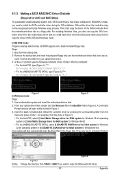
... Intel P55, type (Figure 1): (Note) A:\>copy d:\bootdrv\imsm\32bit\*.* • For the JMB362/GIGABYTE SATA2, type (Figure 2): (Note) A:\>copy d:\bootdrv\gsata\32bit\*.* Figure 1 In Windows mode: Figure 2 Steps: 1: Use an alternative system and insert the motherboard driver disk. 2: From your optical drive is /are configured to RAID/AHCI mode, you also can copy the SATA controller driver from the startup disk. 2: Remove the startup disk and insert the prepared floppy disk and the motherboard driver disk...
... Intel P55, type (Figure 1): (Note) A:\>copy d:\bootdrv\imsm\32bit\*.* • For the JMB362/GIGABYTE SATA2, type (Figure 2): (Note) A:\>copy d:\bootdrv\gsata\32bit\*.* Figure 1 In Windows mode: Figure 2 Steps: 1: Use an alternative system and insert the motherboard driver disk. 2: From your optical drive is /are configured to RAID/AHCI mode, you also can copy the SATA controller driver from the startup disk. 2: Remove the startup disk and insert the prepared floppy disk and the motherboard driver disk...
Manual
Page 99
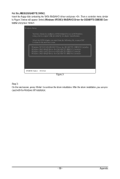
... can proceed with Windows, using a device support disk provided by an adapter manufacturer. After the driver installation, you want from the following list, or press ESC to return to the previous screen. (Windows XP/2003) RAID/AHCI Driver for GIGABYTE GBB36X Controller (Windows 2000) RAID Driver for GIGABYTE GBB363 Controller (Windows 2000) AHCI Driver for GIGABYTE GBB363 Controller (Windows 2000) RAID Driver for GIGABYTE GBB360 Controller ENTER=Select F3=Exit Figure 3 Step 3: On the next screen, press to continue the driver installation. Windows Setup You have...
... can proceed with Windows, using a device support disk provided by an adapter manufacturer. After the driver installation, you want from the following list, or press ESC to return to the previous screen. (Windows XP/2003) RAID/AHCI Driver for GIGABYTE GBB36X Controller (Windows 2000) RAID Driver for GIGABYTE GBB363 Controller (Windows 2000) AHCI Driver for GIGABYTE GBB363 Controller (Windows 2000) RAID Driver for GIGABYTE GBB360 Controller ENTER=Select F3=Exit Figure 3 Step 3: On the next screen, press to continue the driver installation. Windows Setup You have...
Manual
Page 116
... possible computer problems. (For reference only.) 1 short: System boots successfully 1 long, 3 short: Keyboard error 2 short: CMOS setting error 1 long, 9 short: BIOS ROM error 1 long, 1 short: Memory or motherboard error Continuous long beeps: Graphics card not inserted properly 1 long, 2 short: Monitor or graphics card error Continuous short beeps: Power error Appendix - 116 - If not, try a speaker with an internal amplifier. If yes, please disable this device. (If not, skip this jumper, refer to the maximum volume? In the Main Menu, press + to clear the CMOS values...
... possible computer problems. (For reference only.) 1 short: System boots successfully 1 long, 3 short: Keyboard error 2 short: CMOS setting error 1 long, 9 short: BIOS ROM error 1 long, 1 short: Memory or motherboard error Continuous long beeps: Graphics card not inserted properly 1 long, 2 short: Monitor or graphics card error Continuous short beeps: Power error Appendix - 116 - If not, try a speaker with an internal amplifier. If yes, please disable this device. (If not, skip this jumper, refer to the maximum volume? In the Main Menu, press + to clear the CMOS values...


