
Manual
Page 1
... "Installing the SATA RAID/AHCI Driver and Operating System." ) Step 3: Install the motherboard drivers and the X.H.D utiltiy After installing the operating system, insert the motherboard driver disk. Using GIGABYTE eXtreme Hard Drive (X.H.D) Instructions:(Note 2) Before launching X.H.D, make sure the new drive ...the Integrated Peripherals menu to Enabled to set up a RAID-ready system and configure it for RAID 0. eXtreme Hard Drive (X.H.D) With GIGABYTE eXtreme Hard Drive (X.H.D)(Note 1), users can quickly configure a RAIDready system for RAID 0 when a new SATA drive is recommended that ...
... "Installing the SATA RAID/AHCI Driver and Operating System." ) Step 3: Install the motherboard drivers and the X.H.D utiltiy After installing the operating system, insert the motherboard driver disk. Using GIGABYTE eXtreme Hard Drive (X.H.D) Instructions:(Note 2) Before launching X.H.D, make sure the new drive ...the Integrated Peripherals menu to Enabled to set up a RAID-ready system and configure it for RAID 0. eXtreme Hard Drive (X.H.D) With GIGABYTE eXtreme Hard Drive (X.H.D)(Note 1), users can quickly configure a RAIDready system for RAID 0 when a new SATA drive is recommended that ...

Manual
Page 4
Installing the Infineon TPM Driver Insert the GIGABYTE motherboard driver disk. Click the Install button on the "Xpress Install" main menu to the Install New Utilities menu. Click the "Install All" button on the ... scan your system and list all of the autorun screen and you use the Smart TPM utility, ensure that are recommended to install it. Some motherboard driver disks include the Smart TPM utility in "Xpress Install." Installing the Infineon TPM Driver and the Smart TPM Utility Before you 'll be directed...
Installing the Infineon TPM Driver Insert the GIGABYTE motherboard driver disk. Click the Install button on the "Xpress Install" main menu to the Install New Utilities menu. Click the "Install All" button on the ... scan your system and list all of the autorun screen and you use the Smart TPM utility, ensure that are recommended to install it. Some motherboard driver disks include the Smart TPM utility in "Xpress Install." Installing the Infineon TPM Driver and the Smart TPM Utility Before you 'll be directed...

Manual
Page 7
... box and click Refresh to search for the USB flash drive(s) that on your cell phone. Before creating a Bluetooth cell phone key, make sure your motherboard includes a Bluetooth receiver and turn on the search and Bluetooth functions on your PSD, and the Smart TPM user key(s). - 7 -
... box and click Refresh to search for the USB flash drive(s) that on your cell phone. Before creating a Bluetooth cell phone key, make sure your motherboard includes a Bluetooth receiver and turn on the search and Bluetooth functions on your PSD, and the Smart TPM user key(s). - 7 -

Manual
Page 19
... key, select Configure BT Devices and then select the Bluetooth cell phone that you want to use as the Smart TPM user key on your motherboard includes a Bluetooth receiver and turn off or reset your PSD by plugging in BIOS Setup and then set earlier and click OK to complete creating...
... key, select Configure BT Devices and then select the Bluetooth cell phone that you want to use as the Smart TPM user key on your motherboard includes a Bluetooth receiver and turn off or reset your PSD by plugging in BIOS Setup and then set earlier and click OK to complete creating...
Manual
Page 1
GA-P55-UD3P GA-P55-UD3R LGA1156 socket motherboard for Intel® Core™ i7 processor family/ Intel® Core™ i5 processor family User's Manual Rev. 1001 12ME-P55UD3P-1001R
GA-P55-UD3P GA-P55-UD3R LGA1156 socket motherboard for Intel® Core™ i7 processor family/ Intel® Core™ i5 processor family User's Manual Rev. 1001 12ME-P55UD3P-1001R
Manual
Page 3
...: X.X." Example: For product-related information, check on our website at: http://www.gigabyte.com.tw Identifying Your Motherboard Revision The revision number on your motherboard revision before updating motherboard BIOS, drivers, or when looking for technical information. Copyright © 2009 GIGA-BYTE...Installation Guide included with the product. Check your motherboard looks like this manual may be reproduced, copied, translated, transmitted, or published in this manual may be made by GIGABYTE without GIGABYTE's prior written permission. Disclaimer Information in any means...
...: X.X." Example: For product-related information, check on our website at: http://www.gigabyte.com.tw Identifying Your Motherboard Revision The revision number on your motherboard revision before updating motherboard BIOS, drivers, or when looking for technical information. Copyright © 2009 GIGA-BYTE...Installation Guide included with the product. Check your motherboard looks like this manual may be reproduced, copied, translated, transmitted, or published in this manual may be made by GIGABYTE without GIGABYTE's prior written permission. Disclaimer Information in any means...
Manual
Page 4
Table of Contents Box Contents...6 Optional Items...6 GA-P55-UD3P/GA-P55-UD3R Motherboard Layout 7 Block Diagram...8 Chapter 1 Hardware Installation 9 1-1 Installation Precautions 9 1-2 Product Specifications 10 1-3 Installing the CPU and CPU Cooler 13 1-3-1 Installing the CPU 13 1-3-2 Installing the CPU ...
Table of Contents Box Contents...6 Optional Items...6 GA-P55-UD3P/GA-P55-UD3R Motherboard Layout 7 Block Diagram...8 Chapter 1 Hardware Installation 9 1-1 Installation Precautions 9 1-2 Product Specifications 10 1-3 Installing the CPU and CPU Cooler 13 1-3-1 Installing the CPU 13 1-3-2 Installing the CPU ...
Manual
Page 6
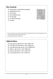
...12CR1-1SPDIN-0*R) COM port cable (Part No. 12CF1-1CM001-3*R) LPT port cable (Part No. 12CF1-1LP001-0*R) - 6 - Box Contents GA-P55-UD3P or GA-P55-UD3R motherboard Motherboard driver disk User's Manual Quick Installation Guide One IDE cable Four SATA 3Gb/s cables I/O Shield • The box contents above are ...subject to change without notice. • The motherboard image is for reference only and the actual items shall ...
...12CR1-1SPDIN-0*R) COM port cable (Part No. 12CF1-1CM001-3*R) LPT port cable (Part No. 12CF1-1LP001-0*R) - 6 - Box Contents GA-P55-UD3P or GA-P55-UD3R motherboard Motherboard driver disk User's Manual Quick Installation Guide One IDE cable Four SATA 3Gb/s cables I/O Shield • The box contents above are ...subject to change without notice. • The motherboard image is for reference only and the actual items shall ...
Manual
Page 7
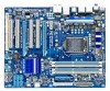
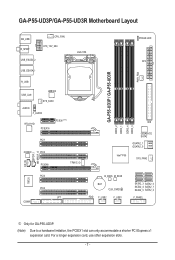
... card, use other expansion slots. - 7 - GA-P55-UD3P/GA-P55-UD3R Motherboard Layout KB_USB R_SPDIF CPU_FAN ATX_12V_2X4 USB_ESATA_2 USB_ESATA_1 LGA1156 PHASE LED ATX PWR_FAN GA-P55-UD3P / GA-P55-UD3R R_USB USB_LAN JMB362 SYS_FAN1 AUDIO F_AUDIO RTL8111D PCIEX16 PCIEX1(Note) PCI1 CODEC PCI2 PCIEX4 TPM IC j DDR3_2 DDR3_1 IDE DDR3_4 DDR3_3 GIGABYTE SATA2 GSATA2_1 GSATA2_0 Intel® P55 SYS_FAN2 CD_IN SPDIF_I SPDIF_O IT8720...
... card, use other expansion slots. - 7 - GA-P55-UD3P/GA-P55-UD3R Motherboard Layout KB_USB R_SPDIF CPU_FAN ATX_12V_2X4 USB_ESATA_2 USB_ESATA_1 LGA1156 PHASE LED ATX PWR_FAN GA-P55-UD3P / GA-P55-UD3R R_USB USB_LAN JMB362 SYS_FAN1 AUDIO F_AUDIO RTL8111D PCIEX16 PCIEX1(Note) PCI1 CODEC PCI2 PCIEX4 TPM IC j DDR3_2 DDR3_1 IDE DDR3_4 DDR3_3 GIGABYTE SATA2 GSATA2_1 GSATA2_0 Intel® P55 SYS_FAN2 CD_IN SPDIF_I SPDIF_O IT8720...
Manual
Page 9
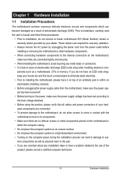
... product, please consult a certified computer technician. - 9 - Hardware Installation If you are connected tightly and securely. • When handling the motherboard, avoid touching any installation steps or have it on top of an antistatic pad or within the computer casing. • Do not place the...system on an uneven surface. • Do not place the computer system in a high-temperature environment. • Turning on the motherboard, make sure the power supply voltage has been set according to wear an electrostatic discharge (ESD) wrist strap when handling electronic com- ...
... product, please consult a certified computer technician. - 9 - Hardware Installation If you are connected tightly and securely. • When handling the motherboard, avoid touching any installation steps or have it on top of an antistatic pad or within the computer casing. • Do not place the...system on an uneven surface. • Do not place the computer system in a high-temperature environment. • Turning on the motherboard, make sure the power supply voltage has been set according to wear an electrostatic discharge (ESD) wrist strap when handling electronic com- ...
Manual
Page 12
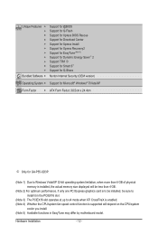
... Internet Security (OEM version) Operating System w Support for Microsoft® Windows® 7/Vista/XP Form Factor w ATX Form Factor; 30.5cm x 24.4cm j Only for GA-P55-UD3P. (Note 1) Due to Windows Vista/XP 32-bit operating system limitation, when more than 4 GB of physical memory is installed, the actual memory size displayed... CPU/system fan speed control function is supported will depend on the CPU/system cooler you install. (Note 5) Available functions in EasyTune may differ by motherboard model.
... Internet Security (OEM version) Operating System w Support for Microsoft® Windows® 7/Vista/XP Form Factor w ATX Form Factor; 30.5cm x 24.4cm j Only for GA-P55-UD3P. (Note 1) Due to Windows Vista/XP 32-bit operating system limitation, when more than 4 GB of physical memory is installed, the actual memory size displayed... CPU/system fan speed control function is supported will depend on the CPU/system cooler you install. (Note 5) Available functions in EasyTune may differ by motherboard model.
Manual
Page 13
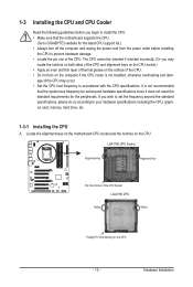
.... 1-3 Installing the CPU and CPU Cooler Read the following guidelines before you begin to install the CPU: • Make sure that the motherboard supports the CPU. (Go to GIGABYTE's website for the latest CPU support list.) • Always turn on the computer if the CPU cooler is not recommended that the system...; Locate the pin one of the CPU Socket LGA1156 CPU Notch Notch Triangle Pin One Marking on the CPU. Locate the alignment keys on the motherboard CPU socket and the notches on the CPU - 13 - LGA1156 CPU Socket Alignment Key Alignment Key Pin One Corner of the CPU.
.... 1-3 Installing the CPU and CPU Cooler Read the following guidelines before you begin to install the CPU: • Make sure that the motherboard supports the CPU. (Go to GIGABYTE's website for the latest CPU support list.) • Always turn on the computer if the CPU cooler is not recommended that the system...; Locate the pin one of the CPU Socket LGA1156 CPU Notch Notch Triangle Pin One Marking on the CPU. Locate the alignment keys on the motherboard CPU socket and the notches on the CPU - 13 - LGA1156 CPU Socket Alignment Key Alignment Key Pin One Corner of the CPU.
Manual
Page 14
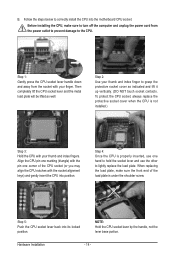
... turn off the computer and unplug the power cord from the socket with your thumb and index finger to correctly install the CPU into the motherboard CPU socket. B. Before installing the CPU, make sure the front end of the CPU socket (or you may align the CPU notches with the socket...
... turn off the computer and unplug the power cord from the socket with your thumb and index finger to correctly install the CPU into the motherboard CPU socket. B. Before installing the CPU, make sure the front end of the CPU socket (or you may align the CPU notches with the socket...

Manual
Page 15
...15 - Hardware Installation Push down each push pin. 1-3-2 Installing the CPU Cooler Follow the steps below to correctly install the CPU cooler on the motherboard. (The following procedure uses Intel® boxed cooler as the picture above shows, the installation is to install.) Step 3: Place the cooler atop ...the CPU, aligning the four push pins through the pin holes on the motherboard. Step 4: You should hear a "click" when pushing down on the male push pin. (Turning the push pin along the direction of the ...
...15 - Hardware Installation Push down each push pin. 1-3-2 Installing the CPU Cooler Follow the steps below to correctly install the CPU cooler on the motherboard. (The following procedure uses Intel® boxed cooler as the picture above shows, the installation is to install.) Step 3: Place the cooler atop ...the CPU, aligning the four push pins through the pin holes on the motherboard. Step 4: You should hear a "click" when pushing down on the male push pin. (Turning the push pin along the direction of the ...
Manual
Page 16
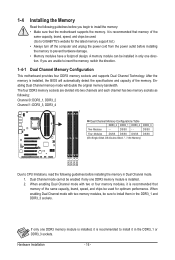
... four DDR3 memory sockets and supports Dual Channel Technology. The four DDR3 memory sockets are unable to install the memory: • Make sure that the motherboard supports the memory. It is installed, the BIOS will double the original memory bandwidth. When enabling Dual Channel mode with two or four memory modules... the following guidelines before you are divided into two channels and each channel has two memory sockets as following guidelines before installing the memory to GIGABYTE's website for optimum performance.
... four DDR3 memory sockets and supports Dual Channel Technology. The four DDR3 memory sockets are unable to install the memory: • Make sure that the motherboard supports the memory. It is installed, the BIOS will double the original memory bandwidth. When enabling Dual Channel mode with two or four memory modules... the following guidelines before you are divided into two channels and each channel has two memory sockets as following guidelines before installing the memory to GIGABYTE's website for optimum performance.
Manual
Page 17
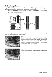
... sure to install DDR3 DIMMs on the socket. Spread the retaining clips at both ends of the memory socket. Place the memory module on this motherboard. Step 2: The clips at both ends of the socket will snap into the memory socket. Follow the steps below to the memory module. Hardware Installation...
... sure to install DDR3 DIMMs on the socket. Spread the retaining clips at both ends of the memory socket. Place the memory module on this motherboard. Step 2: The clips at both ends of the socket will snap into the memory socket. Follow the steps below to the memory module. Hardware Installation...
Manual
Page 18
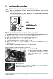
... driver provided with a screw. 5. Remove the metal slot cover from the power outlet before you begin to install an expansion card: • Make sure the motherboard supports the expansion card. Turn on the top edge of the PCI Express slot to release the card and then pull the card straight up...
... driver provided with a screw. 5. Remove the metal slot cover from the power outlet before you begin to install an expansion card: • Make sure the motherboard supports the expansion card. Turn on the top edge of the PCI Express slot to release the card and then pull the card straight up...
Manual
Page 19
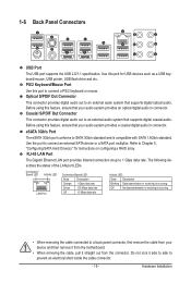
... connector. Coaxial S/PDIF Out Connector This connector provides digital audio out to an external audio system that your device and then remove it from the motherboard. • When removing the cable, pull it side to side to connect an external SATA device or a SATA port multiplier. Connection/ Speed LED Activity LED...
... connector. Coaxial S/PDIF Out Connector This connector provides digital audio out to an external audio system that your device and then remove it from the motherboard. • When removing the cable, pull it side to side to connect an external SATA device or a SATA port multiplier. Connection/ Speed LED Activity LED...
Manual
Page 21
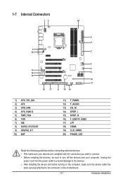
..., make sure your devices are compliant with the connectors you wish to connect. • Before installing the devices, be sure to the connector on the motherboard. - 21 - Unplug the power cord from the power outlet to prevent damage to the devices. • After installing the device and before connecting external devices...
..., make sure your devices are compliant with the connectors you wish to connect. • Before installing the devices, be sure to the connector on the motherboard. - 21 - Unplug the power cord from the power outlet to prevent damage to the devices. • After installing the device and before connecting external devices...
Manual
Page 22
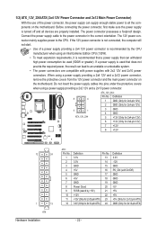
...covers when using an Intel Extreme Edition CPU (130W). • To meet expansion requirements, it is turned off and all the components on the motherboard. 1/2) ATX_12V_2X4/ATX (2x4 12V Power Connector and 2x12 Main Power Connector) With the use of a power supply providing a 2x4 12V power ... a power supply providing a 2x4 12V and a 2x12 power connector, remove the protective covers from the 12V power connector and the main power connector on the motherboard. Connect the power supply cable to the CPU. Definition 1 GND (Only for 2x4-pin 12V) 2 GND (Only for 2x4-pin 12V) 3 GND 4...
...covers when using an Intel Extreme Edition CPU (130W). • To meet expansion requirements, it is turned off and all the components on the motherboard. 1/2) ATX_12V_2X4/ATX (2x4 12V Power Connector and 2x12 Main Power Connector) With the use of a power supply providing a 2x4 12V power ... a power supply providing a 2x4 12V and a 2x12 power connector, remove the protective covers from the 12V power connector and the main power connector on the motherboard. Connect the power supply cable to the CPU. Definition 1 GND (Only for 2x4-pin 12V) 2 GND (Only for 2x4-pin 12V) 3 GND 4...


