
Manual
Page 1
... X.H.D utility. (Note 1) The X.H.D utility only supports the SATA controllers integrated in the array. ) 1. The following procedure details the steps to set eXtreme Hard Drive (X.H.D) under the Integrated Peripherals menu to Enabled to automatically set up a RAID 0 array later using the Auto function. Step 2: Install the RAID driver and operating system The X.H.D utility supports Windows 7/Vista/XP. Without the driver, the hard drive may not be able to enable RAID for complex and time-consuming configurations. All...
... X.H.D utility. (Note 1) The X.H.D utility only supports the SATA controllers integrated in the array. ) 1. The following procedure details the steps to set eXtreme Hard Drive (X.H.D) under the Integrated Peripherals menu to Enabled to automatically set up a RAID 0 array later using the Auto function. Step 2: Install the RAID driver and operating system The X.H.D utility supports Windows 7/Vista/XP. Without the driver, the hard drive may not be able to enable RAID for complex and time-consuming configurations. All...
Manual
Page 3
... your motherboard revision before updating motherboard BIOS, drivers, or when looking for technical information. Example: Changes to their respective owners. For instructions on our website. Disclaimer Information in the use GIGABYTE's unique features, read the User's Manual. For detailed product information, carefully read or download the information on/from the Support&Downloads\Motherboard\Technology Guide page on how to use of this manual are legally registered to the specifications and...
... your motherboard revision before updating motherboard BIOS, drivers, or when looking for technical information. Example: Changes to their respective owners. For instructions on our website. Disclaimer Information in the use GIGABYTE's unique features, read the User's Manual. For detailed product information, carefully read or download the information on/from the Support&Downloads\Motherboard\Technology Guide page on how to use of this manual are legally registered to the specifications and...
Manual
Page 4
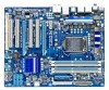
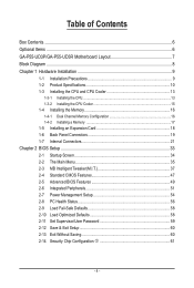
Table of Contents Box Contents...6 Optional Items...6 GA-P55-UD3P/GA-P55-UD3R Motherboard Layout 7 Block Diagram...8 Chapter 1 Hardware Installation 9 1-1 Installation Precautions 9 1-2 Product Specifications 10 1-3 Installing the CPU and CPU Cooler 13 1-3-1 Installing the CPU 13 1-3-2 Installing the CPU Cooler 15 1-4 Installing the Memory 16 1-4-1 Dual Channel Memory Configuration 16 1-4-2 Installing a Memory 17 1-5 Installing an Expansion Card 18 1-6 Back Panel Connectors 19 1-7 Internal Connectors 21 Chapter 2 BIOS Setup 33 2-1 Startup Screen 34 2-2 The Main Menu 35 2-3 MB ...
Table of Contents Box Contents...6 Optional Items...6 GA-P55-UD3P/GA-P55-UD3R Motherboard Layout 7 Block Diagram...8 Chapter 1 Hardware Installation 9 1-1 Installation Precautions 9 1-2 Product Specifications 10 1-3 Installing the CPU and CPU Cooler 13 1-3-1 Installing the CPU 13 1-3-2 Installing the CPU Cooler 15 1-4 Installing the Memory 16 1-4-1 Dual Channel Memory Configuration 16 1-4-2 Installing a Memory 17 1-5 Installing an Expansion Card 18 1-6 Back Panel Connectors 19 1-7 Internal Connectors 21 Chapter 2 BIOS Setup 33 2-1 Startup Screen 34 2-2 The Main Menu 35 2-3 MB ...
Manual
Page 11
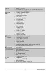
...w Integrated in the Chipset Up to 14 USB 2.0/1.1 ports (10 on the back panel, 4 via the USB brackets connected to the internal USB headers) 1 x 24-pin ATX main power connector 1 x 8-pin ATX 12V power connector 1 x floppy disk drive connector 1 x IDE connector 8 x SATA 3Gb/s connectors 1 x CPU fan header 2 x system fan headers 1 x power fan header 1 x front panel header 1 x front panel audio header 1 x CD In connector 1 x S/PDIF In header 1 x S/PDIF Out header 2 x USB 2.0/1.1 headers 1 x serial port header 1 x parallel port header 1 x clearing CMOS jumper 1 x PS/2 keyboard or PS/2 mouse...
...w Integrated in the Chipset Up to 14 USB 2.0/1.1 ports (10 on the back panel, 4 via the USB brackets connected to the internal USB headers) 1 x 24-pin ATX main power connector 1 x 8-pin ATX 12V power connector 1 x floppy disk drive connector 1 x IDE connector 8 x SATA 3Gb/s connectors 1 x CPU fan header 2 x system fan headers 1 x power fan header 1 x front panel header 1 x front panel audio header 1 x CD In connector 1 x S/PDIF In header 1 x S/PDIF Out header 2 x USB 2.0/1.1 headers 1 x serial port header 1 x parallel port header 1 x clearing CMOS jumper 1 x PS/2 keyboard or PS/2 mouse...
Manual
Page 16
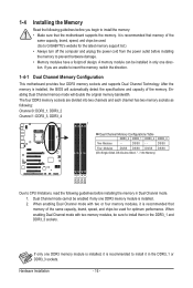
... sockets. Enabling Dual Channel memory mode will automatically detect the specifications and capacity of the same capacity, brand, speed, and chips be enabled if only one direction. Dual Channel mode cannot be used . (Go to GIGABYTE's website for optimum performance. When enabling Dual Channel mode with two or four memory modules, it in only one DDR3 memory module is installed, the BIOS will double the original memory bandwidth. A memory module can be used for the latest memory support list...
... sockets. Enabling Dual Channel memory mode will automatically detect the specifications and capacity of the same capacity, brand, speed, and chips be enabled if only one direction. Dual Channel mode cannot be used . (Go to GIGABYTE's website for optimum performance. When enabling Dual Channel mode with two or four memory modules, it in only one DDR3 memory module is installed, the BIOS will double the original memory bandwidth. A memory module can be used for the latest memory support list...
Manual
Page 30
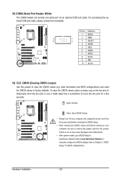
date information and BIOS configurations) and reset the CMOS values to clear the CMOS values (e.g. Failure to do so may cause damage to the motherboard. • After system restart, go to BIOS Setup to load factory defaults (select Load Optimized Defaults) or manually configure the BIOS settings (refer to Chapter 2, "BIOS Setup," for a few seconds. Hardware Installation - 30 - To clear the CMOS values, place a jumper cap on the two pins to temporarily short the two pins or use a metal...
date information and BIOS configurations) and reset the CMOS values to clear the CMOS values (e.g. Failure to do so may cause damage to the motherboard. • After system restart, go to BIOS Setup to load factory defaults (select Load Optimized Defaults) or manually configure the BIOS settings (refer to Chapter 2, "BIOS Setup," for a few seconds. Hardware Installation - 30 - To clear the CMOS values, place a jumper cap on the two pins to temporarily short the two pins or use a metal...

Manual
Page 34
... boot from the device configured in Boot Menu. You can be based on page 50. : BIOS SETUP\Q-FLASH Press the key to enter BIOS Setup or to access the Q-Flash utility in Boot Menu is effective for subsequent access to the instructions on the Full Screen LOGO Show item on BIOS Setup settings. To show the BIOS POST screen. BIOS Setup - 34 - To exit Boot Menu, press . Motherboard Model BIOS Version P55-UD3P D6 . . . . : BIOS Setup : XpressRecovery2 : Boot Menu : Qflash 07/08/2009-P55-7A89RG0JC-00 Function Keys Function Keys Function Keys: : POST SCREEN Press the key...
... boot from the device configured in Boot Menu. You can be based on page 50. : BIOS SETUP\Q-FLASH Press the key to enter BIOS Setup or to access the Q-Flash utility in Boot Menu is effective for subsequent access to the instructions on the Full Screen LOGO Show item on BIOS Setup settings. To show the BIOS POST screen. BIOS Setup - 34 - To exit Boot Menu, press . Motherboard Model BIOS Version P55-UD3P D6 . . . . : BIOS Setup : XpressRecovery2 : Boot Menu : Qflash 07/08/2009-P55-7A89RG0JC-00 Function Keys Function Keys Function Keys: : POST SCREEN Press the key...
Manual
Page 36
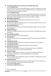
... CPU, memory, etc. Standard CMOS Features Use this menu to configure the system time and date, hard drive types, floppy disk drive types, and the type of errors that stop the system boot, etc. Advanced BIOS Features Use this menu to configure the device boot order, advanced features available on the CPU, and the primary display adapter. Integrated Peripherals Use this menu to configure all peripheral devices, such as IDE, SATA, USB, integrated audio, and integrated LAN, etc. Power Management Setup Use...
... CPU, memory, etc. Standard CMOS Features Use this menu to configure the system time and date, hard drive types, floppy disk drive types, and the type of errors that stop the system boot, etc. Advanced BIOS Features Use this menu to configure the device boot order, advanced features available on the CPU, and the primary display adapter. Integrated Peripherals Use this menu to configure all peripheral devices, such as IDE, SATA, USB, integrated audio, and integrated LAN, etc. Power Management Setup Use...

Manual
Page 39
... PROCHOT signals. Auto lets the BIOS automatically configure this setting. (Default: Auto) CPU Thermal Monitor (Note) Enables or disables Intel CPU Thermal Monitor function, a CPU overheating protection function. Auto lets the BIOS automatically configure this setting. (Default: Auto) Bi-Directional PROCHOT (Note) Auto Lets BIOS automatically configure this setting. (Default) Enabled When the CPU or chipset detects that supports this feature. When enabled, the CPU core frequency and voltage will allow a platform to decrease power consumption. Virtualization enhanced by...
... PROCHOT signals. Auto lets the BIOS automatically configure this setting. (Default: Auto) CPU Thermal Monitor (Note) Enables or disables Intel CPU Thermal Monitor function, a CPU overheating protection function. Auto lets the BIOS automatically configure this setting. (Default: Auto) Bi-Directional PROCHOT (Note) Auto Lets BIOS automatically configure this setting. (Default) Enabled When the CPU or chipset detects that supports this feature. When enabled, the CPU core frequency and voltage will allow a platform to decrease power consumption. Virtualization enhanced by...
Manual
Page 45
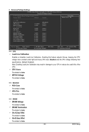
..., keeping the CPU voltage more constant under light and heavy CPU load. Disabled sets the CPU voltage following Intel specifications. (Default: Disabled) Note: Enabling Load-Line Calibration may result in damage to your CPU or reduce the useful life of the CPU. CPU PLL The default is Auto. >>> DRAM DRAM Voltage The default is Auto. Advanced Voltage Settings CMOS Setup Utility-Copyright (C) 1984-2009 Award Software Advanced Voltage Settings ****** Mother Board Voltage Control ****** Voltage Types Normal Current >>> CPU Load-Line Calibration [Disabled] CPU Vcore...
..., keeping the CPU voltage more constant under light and heavy CPU load. Disabled sets the CPU voltage following Intel specifications. (Default: Disabled) Note: Enabling Load-Line Calibration may result in damage to your CPU or reduce the useful life of the CPU. CPU PLL The default is Auto. >>> DRAM DRAM Voltage The default is Auto. Advanced Voltage Settings CMOS Setup Utility-Copyright (C) 1984-2009 Award Software Advanced Voltage Settings ****** Mother Board Voltage Control ****** Voltage Types Normal Current >>> CPU Load-Line Calibration [Disabled] CPU Vcore...
Manual
Page 46
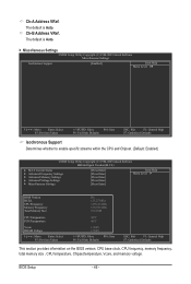
... the CPU and Chipset. (Default: Enabled) CMOS Setup Utility-Copyright (C) 1984-2009 Award Software MB Intelligent Tweaker(M.I.T.) } M.I.T Current Status } Advanced Frequency Settings } Advanced Memory Settings } Advanced Voltage Settings } Miscellaneous Settings [Press Enter] [Press Enter] [Press Enter] [Press Enter] [Press Enter] Item Help Menu Level BIOS Version BCLK CPU Frequency Memory Frequency Total Memory Size D6 133.27 MHz 3198.42 MHz 1332.80 MHz 1024 MB CPU Temperature PCH Temperature 45oC 40oC Vcore DRAM Voltage...
... the CPU and Chipset. (Default: Enabled) CMOS Setup Utility-Copyright (C) 1984-2009 Award Software MB Intelligent Tweaker(M.I.T.) } M.I.T Current Status } Advanced Frequency Settings } Advanced Memory Settings } Advanced Voltage Settings } Miscellaneous Settings [Press Enter] [Press Enter] [Press Enter] [Press Enter] [Press Enter] Item Help Menu Level BIOS Version BCLK CPU Frequency Memory Frequency Total Memory Size D6 133.27 MHz 3198.42 MHz 1332.80 MHz 1024 MB CPU Temperature PCH Temperature 45oC 40oC Vcore DRAM Voltage...
Manual
Page 49
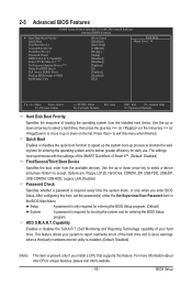
... exit this menu when finished. Options are: Floppy, LS120, Hard Disk, CDROM, ZIP, USB-FDD, USB-ZIP, USB-CDROM, USB-HDD, Legacy LAN, Disabled. Password Check Specifies whether a password is required for booting the system and for entering the BIOS Setup program. (Default) System A password is required every time the system boots, or only when you install a CPU that supports this item, set the password(s) under the Set Supervisor/User Password item in the BIOS Main Menu. Setup A password is only required for entering the BIOS Setup program...
... exit this menu when finished. Options are: Floppy, LS120, Hard Disk, CDROM, ZIP, USB-FDD, USB-ZIP, USB-CDROM, USB-HDD, Legacy LAN, Disabled. Password Check Specifies whether a password is required for booting the system and for entering the BIOS Setup program. (Default) System A password is required every time the system boots, or only when you install a CPU that supports this item, set the password(s) under the Set Supervisor/User Password item in the BIOS Main Menu. Setup A password is only required for entering the BIOS Setup program...

Manual
Page 51
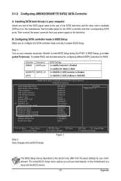
... CMOS Setup Utility-Copyright (C) 1984-2009 Award Software Integrated Peripherals SATA RAID/AHCI Mode SATA Port0-3 Native Mode USB Controllers USB Legacy Function USB Storage Function Azalia Codec Onboard H/W LAN Green LAN } SMART LAN Onboard LAN Boot ROM eSATA Controller eSATA Ctrl Mode GSATA 0_1/IDE Controller GSATA 0_1/IDE Ctrl Mode Onboard Serial Port 1 Onboard Parallel Port Parallel Port Mode [Disabled] [Enabled] [Enabled] [Enabled] [Enabled] [Auto] [Enabled] [Disabled] [Press Enter] [Disabled] [Enabled] [IDE] [Enabled] [IDE...
... CMOS Setup Utility-Copyright (C) 1984-2009 Award Software Integrated Peripherals SATA RAID/AHCI Mode SATA Port0-3 Native Mode USB Controllers USB Legacy Function USB Storage Function Azalia Codec Onboard H/W LAN Green LAN } SMART LAN Onboard LAN Boot ROM eSATA Controller eSATA Ctrl Mode GSATA 0_1/IDE Controller GSATA 0_1/IDE Ctrl Mode Onboard Serial Port 1 Onboard Parallel Port Parallel Port Mode [Disabled] [Enabled] [Enabled] [Enabled] [Enabled] [Auto] [Enabled] [Disabled] [Press Enter] [Disabled] [Enabled] [IDE] [Enabled] [IDE...

Manual
Page 53
... serial port and specifies its base I /O address and corresponding interrupt. Parallel Port Mode Selects an operating mode for the SATA controller; BIOS Setup Options are not used in the GIGABYTE SATA2 chip or configures the SATA controller to activate the boot ROM integrated with the onboard LAN chip. (Default: Disabled) eSATA Controller (JMB362 Chip, eSATA Connectors) Enables or disables the SATA controller integrated in the JMB362 chip. (Default: Enabled) eSATA Ctrl Mode (JMB362 Chip, eSATA Connectors) Enables or disables RAID for the SATA controller integrated in IDE...
... serial port and specifies its base I /O address and corresponding interrupt. Parallel Port Mode Selects an operating mode for the SATA controller; BIOS Setup Options are not used in the GIGABYTE SATA2 chip or configures the SATA controller to activate the boot ROM integrated with the onboard LAN chip. (Default: Disabled) eSATA Controller (JMB362 Chip, eSATA Connectors) Enables or disables the SATA controller integrated in the JMB362 chip. (Default: Enabled) eSATA Ctrl Mode (JMB362 Chip, eSATA Connectors) Enables or disables RAID for the SATA controller integrated in IDE...
Manual
Page 56
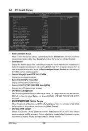
... clear the chassis intrusion status record, set Reset Case Open Status to Enabled, save the settings to the CMOS, and then restart your system. CPU/SYSTEM/POWER FAN Fail Warning Allows the system to emit warning sound if the CPU/system/power fan is removed, this occurs. (Default: Disabled) CPU Smart FAN Control Enables or disables the CPU fan speed control function. Current Voltage(V) Vcore/DDR15V/+5V/+12V Displays the current system voltages. If disabled, the CPU fan runs at different speed according to the CPU temperature...
... clear the chassis intrusion status record, set Reset Case Open Status to Enabled, save the settings to the CMOS, and then restart your system. CPU/SYSTEM/POWER FAN Fail Warning Allows the system to emit warning sound if the CPU/system/power fan is removed, this occurs. (Default: Disabled) CPU Smart FAN Control Enables or disables the CPU fan speed control function. Current Voltage(V) Vcore/DDR15V/+5V/+12V Displays the current system voltages. If disabled, the CPU fan runs at different speed according to the CPU temperature...
Manual
Page 81
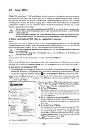
... settings. Smart TPM provides users with an easy-to-use the Clear Security Chip setting (press + in sequence: Step 1: As the computer starts, enter the BIOS Setup program. It's recommended that you use software interface to install it allows you 'll be directed to be saved. j Only for loss of Smart TPM to create a portable user key using a Bluetooth cell phone or USB flash drive. 4-7 Smart TPM j GIGABYTE's unique Smart TPM (Trusted Platform Module) supports...
... settings. Smart TPM provides users with an easy-to-use the Clear Security Chip setting (press + in sequence: Step 1: As the computer starts, enter the BIOS Setup program. It's recommended that you use software interface to install it allows you 'll be directed to be saved. j Only for loss of Smart TPM to create a portable user key using a Bluetooth cell phone or USB flash drive. 4-7 Smart TPM j GIGABYTE's unique Smart TPM (Trusted Platform Module) supports...
Manual
Page 91
...the SATA signal cable to the rear of the SATA hard drive and the other end to the hard drive. ESC: Exit F1: General Help F7: Optimized Defaults The BIOS Setup menus described in your power supply to available SATA port on the motherboard. Appendix In BIOS Setup, go to RAID/IDE CMOS Setup Utility-Copyright (C) 1984-2009 Award Software Integrated Peripherals SATA RAID/AHCI Mode SATA Port0-3 Native Mode USB Controllers USB Legacy Function USB Storage Function Azalia Codec Onboard H/W LAN Green LAN } SMART LAN Onboard LAN Boot ROM eSATA Controller...
...the SATA signal cable to the rear of the SATA hard drive and the other end to the hard drive. ESC: Exit F1: General Help F7: Optimized Defaults The BIOS Setup menus described in your power supply to available SATA port on the motherboard. Appendix In BIOS Setup, go to RAID/IDE CMOS Setup Utility-Copyright (C) 1984-2009 Award Software Integrated Peripherals SATA RAID/AHCI Mode SATA Port0-3 Native Mode USB Controllers USB Legacy Function USB Storage Function Azalia Codec Onboard H/W LAN Green LAN } SMART LAN Onboard LAN Boot ROM eSATA Controller...
Manual
Page 97
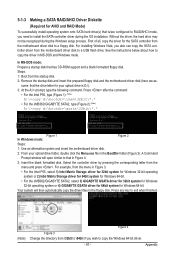
..., type the following command. A Command Prompt window will then automatically copy the driver files to copy the driver in Figure 4. 3: Insert the blank formatted disk. Steps: 1: Boot from the menu and press . Select the controller driver by pressing the corresponding letter from the startup disk. 2: Remove the startup disk and insert the prepared floppy disk and the motherboard driver disk (here we as- 5-1-3 Making a SATA RAID/AHCI Driver Diskette (Required for AHCI and RAID Mode...
..., type the following command. A Command Prompt window will then automatically copy the driver files to copy the driver in Figure 4. 3: Insert the blank formatted disk. Steps: 1: Boot from the menu and press . Select the controller driver by pressing the corresponding letter from the startup disk. 2: Remove the startup disk and insert the prepared floppy disk and the motherboard driver disk (here we as- 5-1-3 Making a SATA RAID/AHCI Driver Diskette (Required for AHCI and RAID Mode...
Manual
Page 99
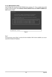
... the next screen, press to continue the driver installation. Then a controller menu similar to configure a SCSI Adapter for GIGABYTE GBB36X Controller and press . Windows Setup You have chosen to Figure 3 below will appear. For the JMB362/GIGABYTE SATA2: Insert the floppy disk containing the SATA RAID/AHCI driver and press . Select (Windows XP/2003) RAID/AHCI Driver for use with the Windows XP installation. - 99 - Select the SCSI Adapter you can proceed with Windows, using a device support disk provided...
... the next screen, press to continue the driver installation. Then a controller menu similar to configure a SCSI Adapter for GIGABYTE GBB36X Controller and press . Windows Setup You have chosen to Figure 3 below will appear. For the JMB362/GIGABYTE SATA2: Insert the floppy disk containing the SATA RAID/AHCI driver and press . Select (Windows XP/2003) RAID/AHCI Driver for use with the Windows XP installation. - 99 - Select the SCSI Adapter you can proceed with Windows, using a device support disk provided...
Manual
Page 116
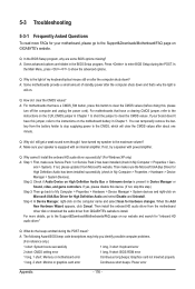
... power after the computer shuts down and that have a CMOS_SW button, press this button to clear the CMOS values (before doing this step.) Step 3: Then go back to My Computer > Properties > Hardware > Device Manager > System devices and right-click on . A: The following Award BIOS beep code descriptions may help you identify possible computer problems. (For reference only.) 1 short: System boots successfully 1 long, 3 short: Keyboard error 2 short: CMOS setting error 1 long, 9 short: BIOS ROM error 1 long, 1 short: Memory or motherboard error Continuous long beeps: Graphics card...
... power after the computer shuts down and that have a CMOS_SW button, press this button to clear the CMOS values (before doing this step.) Step 3: Then go back to My Computer > Properties > Hardware > Device Manager > System devices and right-click on . A: The following Award BIOS beep code descriptions may help you identify possible computer problems. (For reference only.) 1 short: System boots successfully 1 long, 3 short: Keyboard error 2 short: CMOS setting error 1 long, 9 short: BIOS ROM error 1 long, 1 short: Memory or motherboard error Continuous long beeps: Graphics card...


