Manual
Page 3
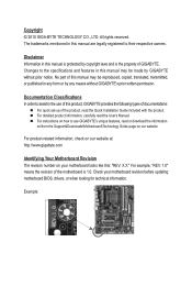
... prior notice. Example: All rights reserved. No part of this manual are legally registered to assist in this product, GIGABYTE provides the following types of documentations: For quick set-up of the product, read the Quick Installation Guide included with ... GIGABYTE's prior written permission. Copyright © 2010 GIGA-BYTE TECHNOLOGY CO., LTD. For detailed product information, carefully read or download the information on/from the Support&Downloads\Motherboard\Technology Guide page on your motherboard revision before updating motherboard BIOS, drivers, or when looking for ...
... prior notice. Example: All rights reserved. No part of this manual are legally registered to assist in this product, GIGABYTE provides the following types of documentations: For quick set-up of the product, read the Quick Installation Guide included with ... GIGABYTE's prior written permission. Copyright © 2010 GIGA-BYTE TECHNOLOGY CO., LTD. For detailed product information, carefully read or download the information on/from the Support&Downloads\Motherboard\Technology Guide page on your motherboard revision before updating motherboard BIOS, drivers, or when looking for ...
Manual
Page 4
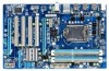
Table of Contents Box Contents...6 Optional Items...6 GA-P55-S3 Motherboard Layout 7 GA-P55-S3 Motherboard Block Diagram 8 Chapter 1 Hardware Installation 9 1-1 Installation Precautions 9 1-2 Product Specifications 10 1-3 Installing the CPU and CPU ...Installing an Expansion Card 17 1-6 Back Panel Connectors 18 1-7 Internal Connectors 19 Chapter 2 BIOS Setup 25 2-1 Startup Screen 26 2-2 The Main Menu 27 2-3 MB Intelligent Tweaker(M.I.T 29 2-4 Standard CMOS Features 38 2-5 Advanced BIOS Features 40 2-6 Integrated Peripherals 42 2-7 Power Management Setup 44 2-8 PC Health Status ...
Table of Contents Box Contents...6 Optional Items...6 GA-P55-S3 Motherboard Layout 7 GA-P55-S3 Motherboard Block Diagram 8 Chapter 1 Hardware Installation 9 1-1 Installation Precautions 9 1-2 Product Specifications 10 1-3 Installing the CPU and CPU ...Installing an Expansion Card 17 1-6 Back Panel Connectors 18 1-7 Internal Connectors 19 Chapter 2 BIOS Setup 25 2-1 Startup Screen 26 2-2 The Main Menu 27 2-3 MB Intelligent Tweaker(M.I.T 29 2-4 Standard CMOS Features 38 2-5 Advanced BIOS Features 40 2-6 Integrated Peripherals 42 2-7 Power Management Setup 44 2-8 PC Health Status ...
Manual
Page 5
... 52 3-4 Contact...53 3-5 System...53 3-6 Download Center 54 3-7 New Utilities...54 Chapter 4 Unique Features 55 4-1 Xpress Recovery2 55 4-2 BIOS Update Utilities 58 4-2-1 Updating the BIOS with the Q-Flash Utility 58 4-2-2 Updating the BIOS with the @BIOS Utility 61 4-3 EasyTune 6...62 4-4 Q-Share...63 4-5 Auto Green...64 Chapter 5 Appendix...65 5-1 Configuring Audio Input and Output 65...
... 52 3-4 Contact...53 3-5 System...53 3-6 Download Center 54 3-7 New Utilities...54 Chapter 4 Unique Features 55 4-1 Xpress Recovery2 55 4-2 BIOS Update Utilities 58 4-2-1 Updating the BIOS with the Q-Flash Utility 58 4-2-2 Updating the BIOS with the @BIOS Utility 61 4-3 EasyTune 6...62 4-4 Q-Share...63 4-5 Auto Green...64 Chapter 5 Appendix...65 5-1 Configuring Audio Input and Output 65...
Manual
Page 8
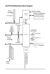
GA-P55-S3 Motherboard Block Diagram PCIe CLK (100 MHz) 1 PCI Express x16 LGA1156 CPU CPU CLK+/- (133 MHz) DDR3 2200/1333/1066/800 MHz Dual Channel Memory PCI Express Bus x16 DMI Interface LAN RJ45 Realtek RTL8111E x1 1 PCI Express x4 x4 PCI Express Bus x1 PCIe CLK (100 MHz) Intel® H55 Dual BIOS 6 SATA 3Gb/s 12 USB 2.0/1.1 PCI Bus PCI Express x1 LPC Bus iTE IT8720 PS/2 KB/Mouse CODEC MIC(Center/Subwoofer Speaker Out) Line Out(Front Speaker Out) Line In(Rear Speaker Out) 4 PCI PCI CLK (33 MHz) - 8 -
GA-P55-S3 Motherboard Block Diagram PCIe CLK (100 MHz) 1 PCI Express x16 LGA1156 CPU CPU CLK+/- (133 MHz) DDR3 2200/1333/1066/800 MHz Dual Channel Memory PCI Express Bus x16 DMI Interface LAN RJ45 Realtek RTL8111E x1 1 PCI Express x4 x4 PCI Express Bus x1 PCIe CLK (100 MHz) Intel® H55 Dual BIOS 6 SATA 3Gb/s 12 USB 2.0/1.1 PCI Bus PCI Express x1 LPC Bus iTE IT8720 PS/2 KB/Mouse CODEC MIC(Center/Subwoofer Speaker Out) Line Out(Front Speaker Out) Line In(Rear Speaker Out) 4 PCI PCI CLK (33 MHz) - 8 -
Manual
Page 11
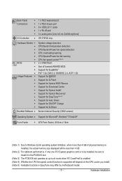
... Connectors w 1 x PS/2 keyboard port w 1 x PS/2 mouse port w 8 x USB 2.0/1.1 ports w 1 x RJ-45 port w 3 x audio jacks (Line In/Line Out/Microphone) I/O Controller w iTE IT8720 chip Hardware Monitor w w w w w w BIOS w w w w Unique Features w w w w w w w w w w System voltage detection CPU/System temperature detection CPU/System/Power fan speed detection CPU overheating warning CPU/System/Power fan fail warning CPU...
... Connectors w 1 x PS/2 keyboard port w 1 x PS/2 mouse port w 8 x USB 2.0/1.1 ports w 1 x RJ-45 port w 3 x audio jacks (Line In/Line Out/Microphone) I/O Controller w iTE IT8720 chip Hardware Monitor w w w w w w BIOS w w w w Unique Features w w w w w w w w w w System voltage detection CPU/System temperature detection CPU/System/Power fan speed detection CPU overheating warning CPU/System/Power fan fail warning CPU...
Manual
Page 15
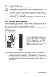
...DS/SS DS/SS (SS=Single-Sided, DS=Double-Sided, "- -"=No Memory) If only one DDR3 memory module is installed, the BIOS will double the original memory bandwidth. DDR3_2 DDR3_1 DDR3_4 DDR3_3 Due to prevent hardware damage. • Memory modules have a foolproof design. ...sure to install the memory: • Make sure that the motherboard supports the memory. A memory module can be used . (Go to GIGABYTE's website for optimum performance. Enabling Dual Channel memory mode will automatically detect the specifications and capacity of the same capacity, brand, speed, and...
...DS/SS DS/SS (SS=Single-Sided, DS=Double-Sided, "- -"=No Memory) If only one DDR3 memory module is installed, the BIOS will double the original memory bandwidth. DDR3_2 DDR3_1 DDR3_4 DDR3_3 Due to prevent hardware damage. • Memory modules have a foolproof design. ...sure to install the memory: • Make sure that the motherboard supports the memory. A memory module can be used . (Go to GIGABYTE's website for optimum performance. Enabling Dual Channel memory mode will automatically detect the specifications and capacity of the same capacity, brand, speed, and...
Manual
Page 17
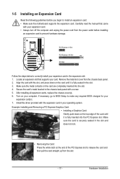
... your expansion card in the slot. 3. PCI Express x1 Slot PCI Express x16 Slot PCI Slot Follow the steps below to make any required BIOS changes for your operating system. If necessary, go to BIOS Setup to correctly install your card. Make sure the card is fully seated in the expansion slot. 1.
... your expansion card in the slot. 3. PCI Express x1 Slot PCI Express x16 Slot PCI Slot Follow the steps below to make any required BIOS changes for your operating system. If necessary, go to BIOS Setup to correctly install your card. Make sure the card is fully seated in the expansion slot. 1.
Manual
Page 22
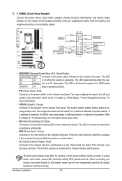
...LED 20 19 SPEAK- RES+ RES- The system reports system startup status by chassis. When connecting your system using the power switch (refer to Chapter 2, "BIOS Setup," "Power Management Setup," for information about beep codes. • HD (Hard Drive Activity LED, Blue) Connects to the hard drive activity LED on... Connects to the power status indicator on the chassis front panel. One single short beep will be heard if no problem is in S3/S4 sleep S3/S4/S5 Off state or powered off your chassis front panel module to indicate the problem. The LED is on when the hard drive...
...LED 20 19 SPEAK- RES+ RES- The system reports system startup status by chassis. When connecting your system using the power switch (refer to Chapter 2, "BIOS Setup," "Power Management Setup," for information about beep codes. • HD (Hard Drive Activity LED, Blue) Connects to the hard drive activity LED on... Connects to the power status indicator on the chassis front panel. One single short beep will be heard if no problem is in S3/S4 sleep S3/S4/S5 Off state or powered off your chassis front panel module to indicate the problem. The LED is on when the hard drive...
Manual
Page 24
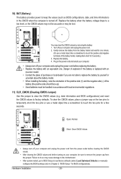
... the battery with local environmental regulations. 11) CLR_CMOS (Clearing CMOS Jumper) Use this jumper to clear the CMOS values (e.g. date information and BIOS configurations) and reset the CMOS values to factory defaults. Failure to do so may clear the CMOS values by yourself or uncertain about the ... turning on the two pins to temporarily short the two pins or use a metal object like a screwdriver to touch the two pins for BIOS configurations). To clear the CMOS values, place a jumper cap on your computer, be lost. You may cause damage to the motherboard. •...
... the battery with local environmental regulations. 11) CLR_CMOS (Clearing CMOS Jumper) Use this jumper to clear the CMOS values (e.g. date information and BIOS configurations) and reset the CMOS values to factory defaults. Failure to do so may clear the CMOS values by yourself or uncertain about the ... turning on the two pins to temporarily short the two pins or use a metal object like a screwdriver to touch the two pins for BIOS configurations). To clear the CMOS values, place a jumper cap on your computer, be lost. You may cause damage to the motherboard. •...
Manual
Page 25
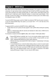
...keep the configuration values in the CMOS. To upgrade the BIOS, use either the GIGABYTE Q-Flash or @BIOS utility. • Q-Flash allows the user to quickly and easily upgrade or back up BIOS without entering the operating system. • @BIOS is recommended that allows the user to modify basic system...Defaults" section in this chapter or introductions of the system in the main menu of BIOS from the Internet and updates the BIOS. To see more advanced BIOS Setup menu options, you not flash the BIOS. Its major functions include conducting the Power-On Self-Test (POST) during system ...
...keep the configuration values in the CMOS. To upgrade the BIOS, use either the GIGABYTE Q-Flash or @BIOS utility. • Q-Flash allows the user to quickly and easily upgrade or back up BIOS without entering the operating system. • @BIOS is recommended that allows the user to modify basic system...Defaults" section in this chapter or introductions of the system in the main menu of BIOS from the Internet and updates the BIOS. To see more advanced BIOS Setup menu options, you not flash the BIOS. Its major functions include conducting the Power-On Self-Test (POST) during system ...
Manual
Page 26
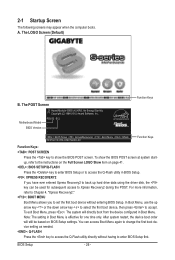
... order will directly boot from the device configured in Boot Menu is effective for subsequent access to access the Q-Flash utility directly without entering BIOS Setup. In Boot Menu, use the up hard drive data using the driver disk, the key can access Boot Menu again to change ...the first boot device setting as needed. : Q-FLASH Press the key to Xpress Recovery2 during the POST. P55-S3 E12 . . . . : BIOS Setup : XpressRecovery2 : Boot Menu : Qflash 05/25/2010-H55-7A89TG0XC-00 Function Keys Function Keys: : POST SCREEN Press the key to show the...
... order will directly boot from the device configured in Boot Menu is effective for subsequent access to access the Q-Flash utility directly without entering BIOS Setup. In Boot Menu, use the up hard drive data using the driver disk, the key can access Boot Menu again to change ...the first boot device setting as needed. : Q-FLASH Press the key to Xpress Recovery2 during the POST. P55-S3 E12 . . . . : BIOS Setup : XpressRecovery2 : Boot Menu : Qflash 05/25/2010-H55-7A89TG0XC-00 Function Keys Function Keys: : POST SCREEN Press the key to show the...
Manual
Page 27
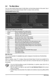
... Without Saving ESC: Quit F8: Q-Flash Select Item F10: Save & Exit Setup Change CPU's Clock & Voltage F11: Save CMOS to BIOS F12: Load CMOS from BIOS BIOS Setup Program Function Keys Move the selection bar to select an item Execute command or enter the submenu Main Menu: Exit the...settings for the current submenus Access the Q-Flash utility Display system information Save all the changes and exit the BIOS Setup program Save CMOS to BIOS Load CMOS from BIOS Main Menu Help The on-screen description of a highlighted setup option is displayed on the right side of...
... Without Saving ESC: Quit F8: Q-Flash Select Item F10: Save & Exit Setup Change CPU's Clock & Voltage F11: Save CMOS to BIOS F12: Load CMOS from BIOS BIOS Setup Program Function Keys Move the selection bar to select an item Execute command or enter the submenu Main Menu: Exit the...settings for the current submenus Access the Q-Flash utility Display system information Save all the changes and exit the BIOS Setup program Save CMOS to BIOS Load CMOS from BIOS Main Menu Help The on-screen description of a highlighted setup option is displayed on the right side of...

Manual
Page 28
... MB Intelligent Tweaker(M.I.T.) Use this menu to configure the clock, frequency and voltages of your system becomes unstable and you have loaded the BIOS default settings, you can create up to a profile. A supervisor password allows you to configure all the power-saving functions. PC ...configure the system time and date, hard drive types, and the type of errors that stop the system boot, etc. Advanced BIOS Features Use this menu to configure the device boot order, advanced features available on the CPU, and the primary display adapter. ...
... MB Intelligent Tweaker(M.I.T.) Use this menu to configure the clock, frequency and voltages of your system becomes unstable and you have loaded the BIOS default settings, you can create up to a profile. A supervisor password allows you to configure all the power-saving functions. PC ...configure the system time and date, hard drive types, and the type of errors that stop the system boot, etc. Advanced BIOS Features Use this menu to configure the device boot order, advanced features available on the CPU, and the primary display adapter. ...
Manual
Page 29
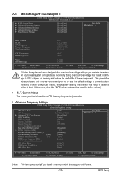
...Voltage Settings } Miscellaneous Settings [Press Enter] [Press Enter] [Press Enter] [Press Enter] [Press Enter] Item Help Menu Level BIOS Version BCLK CPU Frequency Memory Frequency Total Memory Size E12 133.27 MHz 3332.86 MHz 1332.71 MHz 2048 MB CPU Temperature PCH Temperature... overclock/overvoltage may result in damage to CPU, chipset, or memory and reduce the useful life of these components. BIOS Setup 2-3 MB Intelligent Tweaker(M.I.T.) CMOS Setup Utility-Copyright (C) 1984-2010 Award Software MB Intelligent Tweaker(M.I.T.) } M.I .T.
...Voltage Settings } Miscellaneous Settings [Press Enter] [Press Enter] [Press Enter] [Press Enter] [Press Enter] Item Help Menu Level BIOS Version BCLK CPU Frequency Memory Frequency Total Memory Size E12 133.27 MHz 3332.86 MHz 1332.71 MHz 2048 MB CPU Temperature PCH Temperature... overclock/overvoltage may result in damage to CPU, chipset, or memory and reduce the useful life of these components. BIOS Setup 2-3 MB Intelligent Tweaker(M.I.T.) CMOS Setup Utility-Copyright (C) 1984-2010 Award Software MB Intelligent Tweaker(M.I.T.) } M.I .T.
Manual
Page 30
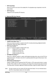
...Help F7: Optimized Defaults Intel(R) Turbo Boost Tech. (Note) Allows you to alter the clock ratio for operating systems that supports this feature. BIOS Setup - 30 - All Enables all CPU cores. This feature only works for the installed CPU. When enabled, the CPU core frequency and voltage...CPU cores. 3 Enables only three CPU cores. For more information about Intel CPUs' unique features, please visit Intel's website. Auto lets the BIOS automatically configure this setting. (Default: Auto) (Note) This item is dependent on the CPU being installed. Auto lets the...
...Help F7: Optimized Defaults Intel(R) Turbo Boost Tech. (Note) Allows you to alter the clock ratio for operating systems that supports this feature. BIOS Setup - 30 - All Enables all CPU cores. This feature only works for the installed CPU. When enabled, the CPU core frequency and voltage...CPU cores. 3 Enables only three CPU cores. For more information about Intel CPUs' unique features, please visit Intel's website. Auto lets the BIOS automatically configure this setting. (Default: Auto) (Note) This item is dependent on the CPU being installed. Auto lets the...
Manual
Page 31
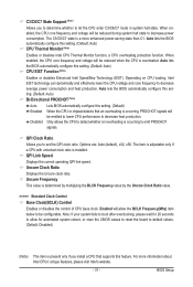
...Link Speed Displays the current operating QPI link speed. C3/C6/C7 State Support (Note) Allows you to set - Auto lets the BIOS automatically configure this set the QPI clock ratio. Note: If your system fails to boot after overclocking, please wait for automated system ...CPU that supports this setting. (Default) When the CPU or chipset detects that an overheating is occurring, PROCHOT signals will be configurable. BIOS Setup Enabled will be emitted to lower CPU performance to decrease power consumption. ting. (Default: Auto) Bi-Directional PROCHOT (Note) Auto ...
...Link Speed Displays the current operating QPI link speed. C3/C6/C7 State Support (Note) Allows you to set - Auto lets the BIOS automatically configure this set the QPI clock ratio. Note: If your system fails to boot after overclocking, please wait for automated system ...CPU that supports this setting. (Default) When the CPU or chipset detects that an overheating is occurring, PROCHOT signals will be configurable. BIOS Setup Enabled will be emitted to lower CPU performance to decrease power consumption. ting. (Default: Auto) Bi-Directional PROCHOT (Note) Auto ...
Manual
Page 32
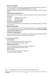
...) (Note) This item appears only if you install a memory module that supports this function. (Default) Profile1 Uses Profile 1 settings. Extreme Memory Profile (X.M.P.) (Note) Allows the BIOS to read the SPD data on XMP memory module(s) to enhance memory performance when enabled. Disabled Disables this feature...
...) (Note) This item appears only if you install a memory module that supports this function. (Default) Profile1 Uses Profile 1 settings. Extreme Memory Profile (X.M.P.) (Note) Allows the BIOS to read the SPD data on XMP memory module(s) to enhance memory performance when enabled. Disabled Disables this feature...
Manual
Page 33
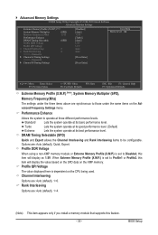
.... DRAM Timing Selectable (SPD) Quick and Expert allows the Channel Interleaving and Rank Interleaving items to those under the three items above are : Auto (default), 1~6. BIOS Setup Standard Lets the system operate at three different performance levels.
.... DRAM Timing Selectable (SPD) Quick and Expert allows the Channel Interleaving and Rank Interleaving items to those under the three items above are : Auto (default), 1~6. BIOS Setup Standard Lets the system operate at three different performance levels.
Manual
Page 34
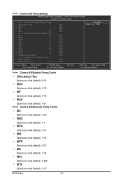
tRP Options are : Auto (default), 1~15. tWR Options are : Auto (default), 1~15. BIOS Setup - 34 - tWTR Options are : Auto (default), 5~15. x Round Trip Latency 36 Auto Auto Auto Auto Auto Auto Auto Auto Auto Auto Auto Auto Auto ...
tRP Options are : Auto (default), 1~15. tWR Options are : Auto (default), 1~15. BIOS Setup - 34 - tWTR Options are : Auto (default), 5~15. x Round Trip Latency 36 Auto Auto Auto Auto Auto Auto Auto Auto Auto Auto Auto Auto Auto ...
Manual
Page 35
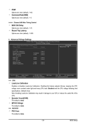
.... Enabling this feature adjusts Vdroop, keeping the CPU voltage more constant under light and heavy CPU load. Dynamic Vcore(DVID) The default is Auto. - 35 - BIOS Setup QPI/Vtt Voltage The default is Auto. >>> MCH/ICH PCH Core The default is Auto. Disabled sets the CPU voltage following Intel specifications. (Default...
.... Enabling this feature adjusts Vdroop, keeping the CPU voltage more constant under light and heavy CPU load. Dynamic Vcore(DVID) The default is Auto. - 35 - BIOS Setup QPI/Vtt Voltage The default is Auto. >>> MCH/ICH PCH Core The default is Auto. Disabled sets the CPU voltage following Intel specifications. (Default...


