Manual
Page 3
... property of this : "REV: X.X." For instructions on how to their respective owners. Documentation Classifications In order to assist in this manual are legally registered to use of GIGABYTE. All rights reserved. Disclaimer Information in the use GIGABYTE's unique features, read or download the information on/from the Support&Downloads\Motherboard\Technology Guide page on your motherboard revision before updating motherboard BIOS, drivers, or when looking for technical...
... property of this : "REV: X.X." For instructions on how to their respective owners. Documentation Classifications In order to assist in this manual are legally registered to use of GIGABYTE. All rights reserved. Disclaimer Information in the use GIGABYTE's unique features, read or download the information on/from the Support&Downloads\Motherboard\Technology Guide page on your motherboard revision before updating motherboard BIOS, drivers, or when looking for technical...
Manual
Page 4
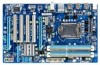
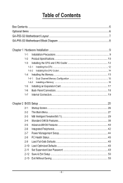
... of Contents Box Contents...6 Optional Items...6 GA-P55-S3 Motherboard Layout 7 GA-P55-S3 Motherboard Block Diagram 8 Chapter 1 Hardware Installation 9 1-1 Installation Precautions 9 1-2 Product Specifications 10 1-3 Installing the CPU and CPU Cooler 12 1-3-1 Installing the CPU 12 1-3-2 Installing the CPU Cooler 14 1-4 Installing the Memory 15 1-4-1 Dual Channel Memory Configuration 15 1-4-2 Installing a Memory 16 1-5 Installing an Expansion Card 17 1-6 Back Panel Connectors 18 1-7 Internal Connectors 19 Chapter 2 BIOS Setup 25 2-1 Startup Screen 26 2-2 The Main Menu 27 2-3 MB...
... of Contents Box Contents...6 Optional Items...6 GA-P55-S3 Motherboard Layout 7 GA-P55-S3 Motherboard Block Diagram 8 Chapter 1 Hardware Installation 9 1-1 Installation Precautions 9 1-2 Product Specifications 10 1-3 Installing the CPU and CPU Cooler 12 1-3-1 Installing the CPU 12 1-3-2 Installing the CPU Cooler 14 1-4 Installing the Memory 15 1-4-1 Dual Channel Memory Configuration 15 1-4-2 Installing a Memory 16 1-5 Installing an Expansion Card 17 1-6 Back Panel Connectors 18 1-7 Internal Connectors 19 Chapter 2 BIOS Setup 25 2-1 Startup Screen 26 2-2 The Main Menu 27 2-3 MB...
Manual
Page 10
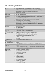
...; 1 x PCI Express x1 slot 4 x PCI slots Multi-Graphics Support for ATI CrossFireX™ technology (Note 3) Technology Storage Interface Chipset: - 6 x SATA 3Gb/s connectors supporting up to the internal USB headers) Internal w 1 x 24-pin ATX main power connector Connectors w 1 x 4-pin ATX 12V power connector w 6 x SATA 3Gb/s connectors w 1 x CPU fan header w 2 x system fan headers w 1 x power fan header w 1 x front panel header w 1 x front panel audio header w 2 x USB 2.0/1.1 headers...
...; 1 x PCI Express x1 slot 4 x PCI slots Multi-Graphics Support for ATI CrossFireX™ technology (Note 3) Technology Storage Interface Chipset: - 6 x SATA 3Gb/s connectors supporting up to the internal USB headers) Internal w 1 x 24-pin ATX main power connector Connectors w 1 x 4-pin ATX 12V power connector w 6 x SATA 3Gb/s connectors w 1 x CPU fan header w 2 x system fan headers w 1 x power fan header w 1 x front panel header w 1 x front panel audio header w 2 x USB 2.0/1.1 headers...
Manual
Page 17
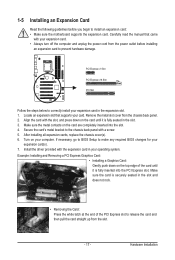
... slot. 3. Example: Installing and Removing a PCI Express Graphics Card: • Installing a Graphics Card: Gently push down on the top edge of the PCI Express slot to make any required BIOS changes for your operating system. Make sure the metal contacts on your expansion card in your expansion card(s). 7. Carefully read the manual that supports your expansion card. • Always turn off the computer and unplug the power cord from the chassis back panel. 2. Hardware Installation...
... slot. 3. Example: Installing and Removing a PCI Express Graphics Card: • Installing a Graphics Card: Gently push down on the top edge of the PCI Express slot to make any required BIOS changes for your operating system. Make sure the metal contacts on your expansion card in your expansion card(s). 7. Carefully read the manual that supports your expansion card. • Always turn off the computer and unplug the power cord from the chassis back panel. 2. Hardware Installation...
Manual
Page 24
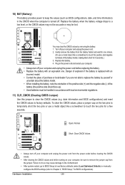
... the battery is turned off. Replace the battery. 4. Gently remove the battery from the jumper. Plug in accordance with local environmental regulations. 11) CLR_CMOS (Clearing CMOS Jumper) Use this jumper to clear the CMOS values (e.g. Open: Normal Short: Clear CMOS Values • Always turn off your computer and unplug the power cord. 2. date information and BIOS configurations) and reset the CMOS values to factory defaults. Danger of the battery holder, making them short for a few seconds. Turn off...
... the battery is turned off. Replace the battery. 4. Gently remove the battery from the jumper. Plug in accordance with local environmental regulations. 11) CLR_CMOS (Clearing CMOS Jumper) Use this jumper to clear the CMOS values (e.g. Open: Normal Short: Clear CMOS Values • Always turn off your computer and unplug the power cord. 2. date information and BIOS configurations) and reset the CMOS values to factory defaults. Danger of the battery holder, making them short for a few seconds. Turn off...
Manual
Page 25
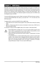
... BIOS, it with caution. Inadequate BIOS flashing may result in Chapter 1 for the beep codes description. • It is a Windows-based utility that you not flash the BIOS. When the power is turned off, the battery on . Refer to Chapter 5, "Troubleshooting," for how to clear the CMOS values.) - 25 - BIOS Setup To upgrade the BIOS, use either the GIGABYTE Q-Flash or @BIOS utility. • Q-Flash allows the user to quickly and easily upgrade or back up BIOS without entering...
... BIOS, it with caution. Inadequate BIOS flashing may result in Chapter 1 for the beep codes description. • It is a Windows-based utility that you not flash the BIOS. When the power is turned off, the battery on . Refer to Chapter 5, "Troubleshooting," for how to clear the CMOS values.) - 25 - BIOS Setup To upgrade the BIOS, use either the GIGABYTE Q-Flash or @BIOS utility. • Q-Flash allows the user to quickly and easily upgrade or back up BIOS without entering...
Manual
Page 26
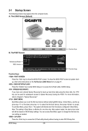
... enter BIOS Setup first. In Boot Menu, use the up hard drive data using the driver disk, the key can access Boot Menu again to change the first boot device setting as needed. : Q-FLASH Press the key to Xpress Recovery2 during the POST. After system restart, the device boot order will directly boot from the device configured in Boot Menu is effective for subsequent access to access the Q-Flash utility directly without entering BIOS Setup. 2-1 Startup Screen The following screens may appear when the computer boots. Note: The setting in Boot Menu...
... enter BIOS Setup first. In Boot Menu, use the up hard drive data using the driver disk, the key can access Boot Menu again to change the first boot device setting as needed. : Q-FLASH Press the key to Xpress Recovery2 during the POST. After system restart, the device boot order will directly boot from the device configured in Boot Menu is effective for subsequent access to access the Q-Flash utility directly without entering BIOS Setup. 2-1 Startup Screen The following screens may appear when the computer boots. Note: The setting in Boot Menu...

Manual
Page 28
... SATA, USB, integrated audio, and integrated LAN, etc. Power Management Setup Use this task.) BIOS Setup - 28 - First enter the profile name (to erase the default profile name, use this function to load the BIOS settings from BIOS If your CPU, memory, etc. Standard CMOS Features Use this menu to configure the system time and date, hard drive types, and the type of errors that stop the system boot, etc. Advanced BIOS Features Use this menu to configure the device boot...
... SATA, USB, integrated audio, and integrated LAN, etc. Power Management Setup Use this task.) BIOS Setup - 28 - First enter the profile name (to erase the default profile name, use this function to load the BIOS settings from BIOS If your CPU, memory, etc. Standard CMOS Features Use this menu to configure the system time and date, hard drive types, and the type of errors that stop the system boot, etc. Advanced BIOS Features Use this menu to configure the device boot...
Manual
Page 29
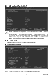
...CMOS Setup Utility-Copyright (C) 1984-2010 Award Software MB Intelligent Tweaker(M.I.T.) } M.I .T. Incorrectly doing overclock/overvoltage may result in damage to default values.) M.I .T Current Status } Advanced Frequency Settings } Advanced Memory Settings } Advanced Voltage Settings } Miscellaneous Settings [Press Enter] [Press Enter] [Press Enter] [Press Enter] [Press Enter] Item Help Menu Level BIOS Version BCLK CPU Frequency Memory Frequency Total Memory Size E12 133.27 MHz 3332.86 MHz 1332.71 MHz 2048 MB CPU Temperature...
...CMOS Setup Utility-Copyright (C) 1984-2010 Award Software MB Intelligent Tweaker(M.I.T.) } M.I .T. Incorrectly doing overclock/overvoltage may result in damage to default values.) M.I .T Current Status } Advanced Frequency Settings } Advanced Memory Settings } Advanced Voltage Settings } Miscellaneous Settings [Press Enter] [Press Enter] [Press Enter] [Press Enter] [Press Enter] Item Help Menu Level BIOS Version BCLK CPU Frequency Memory Frequency Total Memory Size E12 133.27 MHz 3332.86 MHz 1332.71 MHz 2048 MB CPU Temperature...
Manual
Page 30
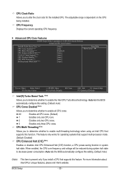
... decrease power consumption. When enabled, the CPU core frequency and voltage will be reduced during system halt state to enable the Intel CPU Turbo Boost technology. All Enables all CPU cores. CPU Clock Ratio Allows you to alter the clock ratio for operating systems that support multi-processor mode. (Default: Enabled) CPU Enhanced Halt (C1E) (Note) Enables or disables Intel CPU Enhanced Halt (C1E) function, a CPU power-saving function in system halt state. Auto lets the BIOS automatically configure...
... decrease power consumption. When enabled, the CPU core frequency and voltage will be reduced during system halt state to enable the Intel CPU Turbo Boost technology. All Enables all CPU cores. CPU Clock Ratio Allows you to alter the clock ratio for operating systems that support multi-processor mode. (Default: Enabled) CPU Enhanced Halt (C1E) (Note) Enables or disables Intel CPU Enhanced Halt (C1E) function, a CPU power-saving function in system halt state. Auto lets the BIOS automatically configure...
Manual
Page 31
... the BIOS automatically configure this setting. (Default: Auto) CPU Thermal Monitor (Note) Enables or disables Intel CPU Thermal Monitor function, a CPU overheating protection function. Depending on CPU loading, Intel EIST technology can dynamically and effectively lower the CPU voltage and core frequency to be reduced during system halt state to decrease heat production. QPI Link Speed Displays the current operating QPI link speed. Enabled will be configurable. C3/C6/C7 State Support (Note) Allows you install a CPU...
... the BIOS automatically configure this setting. (Default: Auto) CPU Thermal Monitor (Note) Enables or disables Intel CPU Thermal Monitor function, a CPU overheating protection function. Depending on CPU loading, Intel EIST technology can dynamically and effectively lower the CPU voltage and core frequency to be reduced during system halt state to decrease heat production. QPI Link Speed Displays the current operating QPI link speed. Enabled will be configurable. C3/C6/C7 State Support (Note) Allows you install a CPU...
Manual
Page 35
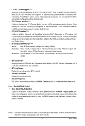
... to your CPU or reduce the useful life of the CPU. Enabling this feature adjusts Vdroop, keeping the CPU voltage more constant under light and heavy CPU load. Round Trip Latency Options are : Auto (default), 1~31. BIOS Setup Command Rate(CMD) Options are: Auto (default), 1~3. >>>>> Channel A/B Misc Timing Control B2B CAS Delay Options are : Auto (default), 1~255. Advanced Voltage Settings CMOS Setup Utility-Copyright (C) 1984-2010 Award Software Advanced Voltage Settings ****** Mother Board Voltage Control ****** Voltage Types Normal Current >>> CPU Load-Line...
... to your CPU or reduce the useful life of the CPU. Enabling this feature adjusts Vdroop, keeping the CPU voltage more constant under light and heavy CPU load. Round Trip Latency Options are : Auto (default), 1~31. BIOS Setup Command Rate(CMD) Options are: Auto (default), 1~3. >>>>> Channel A/B Misc Timing Control B2B CAS Delay Options are : Auto (default), 1~255. Advanced Voltage Settings CMOS Setup Utility-Copyright (C) 1984-2010 Award Software Advanced Voltage Settings ****** Mother Board Voltage Control ****** Voltage Types Normal Current >>> CPU Load-Line...
Manual
Page 36
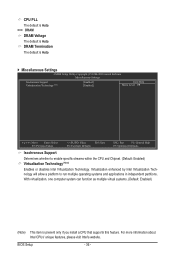
BIOS Setup - 36 - DRAM Termination The default is Auto. Miscellaneous Settings CMOS Setup Utility-Copyright (C) 1984-2010 Award Software Miscellaneous Settings Isochronous Support Virtualization Technology (Note) [Enabled] [Enabled] Item Help Menu Level Move Enter: Select F5: Previous Values +/-/PU/PD: Value F10: Save F6: Fail-Safe Defaults ESC: Exit F1: General Help F7: Optimized Defaults Isochronous Support Determines whether to run multiple operating systems and applications in independent partitions. For more...
BIOS Setup - 36 - DRAM Termination The default is Auto. Miscellaneous Settings CMOS Setup Utility-Copyright (C) 1984-2010 Award Software Miscellaneous Settings Isochronous Support Virtualization Technology (Note) [Enabled] [Enabled] Item Help Menu Level Move Enter: Select F5: Previous Values +/-/PU/PD: Value F10: Save F6: Fail-Safe Defaults ESC: Exit F1: General Help F7: Optimized Defaults Isochronous Support Determines whether to run multiple operating systems and applications in independent partitions. For more...
Manual
Page 38
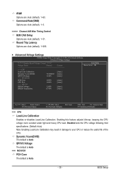
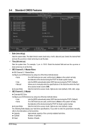
... the hard drive. Options are : Auto (default), CHS, LBA, Large. is week (read-only), month, date and year. Access Mode Sets the hard drive access mode. Access Mode Sets the hard drive access mode. The following fields display your SATA devices by using one of the three methods below : • Auto Lets the BIOS automatically detect SATA devices during the POST. (Default) • None If no SATA devices are used , set the date. Head Number of cylinders. 2-4 Standard CMOS Features CMOS Setup Utility-Copyright (C) 1984-2010 Award Software Standard CMOS...
... the hard drive. Options are : Auto (default), CHS, LBA, Large. is week (read-only), month, date and year. Access Mode Sets the hard drive access mode. Access Mode Sets the hard drive access mode. The following fields display your SATA devices by using one of the three methods below : • Auto Lets the BIOS automatically detect SATA devices during the POST. (Default) • None If no SATA devices are used , set the date. Head Number of cylinders. 2-4 Standard CMOS Features CMOS Setup Utility-Copyright (C) 1984-2010 Award Software Standard CMOS...
Manual
Page 40
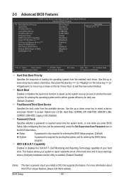
... Set Supervisor/User Password item in the BIOS Main Menu. Setup A password is only required for entering the BIOS Setup program. (Default) System A password is required every time the system boots, or only when you install a CPU that supports this feature. Press to deliver greater efficiency for entering the BIOS Setup program. Use the up or down arrow key to select a device and press to accept. 2-5 Advanced BIOS Features CMOS Setup Utility-Copyright (C) 1984-2010 Award Software Advanced BIOS Features } Hard Disk Boot...
... Set Supervisor/User Password item in the BIOS Main Menu. Setup A password is only required for entering the BIOS Setup program. (Default) System A password is required every time the system boots, or only when you install a CPU that supports this feature. Press to deliver greater efficiency for entering the BIOS Setup program. Use the up or down arrow key to select a device and press to accept. 2-5 Advanced BIOS Features CMOS Setup Utility-Copyright (C) 1984-2010 Award Software Advanced BIOS Features } Hard Disk Boot...
Manual
Page 42
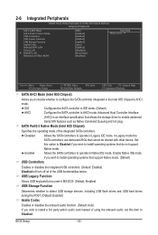
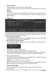
...SATA controllers use dedicated IRQs that allows the storage driver to enable advanced Serial ATA features such as Native Command Queuing and hot plug. USB Legacy Function Allows USB keyboard to be shared with other device. 2-6 Integrated Peripherals CMOS Setup Utility-Copyright (C) 1984-2010 Award Software Integrated Peripherals SATA AHCI Mode SATA Port0-3 Native Mode USB Controllers USB Legacy Function USB Storage Function Azalia Codec Onboard H/W LAN Green LAN } SMART LAN Onboard LAN Boot ROM [IDE] [Enabled] [Enabled] [Enabled] [Enabled] [Auto...
...SATA controllers use dedicated IRQs that allows the storage driver to enable advanced Serial ATA features such as Native Command Queuing and hot plug. USB Legacy Function Allows USB keyboard to be shared with other device. 2-6 Integrated Peripherals CMOS Setup Utility-Copyright (C) 1984-2010 Award Software Integrated Peripherals SATA AHCI Mode SATA Port0-3 Native Mode USB Controllers USB Legacy Function USB Storage Function Azalia Codec Onboard H/W LAN Green LAN } SMART LAN Onboard LAN Boot ROM [IDE] [Enabled] [Enabled] [Enabled] [Enabled] [Auto...
Manual
Page 43
...-Safe Defaults ESC: Exit F1: General Help F7: Optimized Defaults This motherboard incorporates cable diagnostic feature designed to detect the status of the attached LAN cable. BIOS Setup This feature will be disabled automatically. (Default: Disabled) SMART LAN CMOS Setup Utility-Copyright (C) 1984-2010 Award Software SMART LAN Start detecting at Port..... Cable Length Displays the approximate length of the attached LAN cable. Example: Part1-2 Status = Short / Length = 2m Explanation: A fault or short might occur at Port..... If no cable problem is...
...-Safe Defaults ESC: Exit F1: General Help F7: Optimized Defaults This motherboard incorporates cable diagnostic feature designed to detect the status of the attached LAN cable. BIOS Setup This feature will be disabled automatically. (Default: Disabled) SMART LAN CMOS Setup Utility-Copyright (C) 1984-2010 Award Software SMART LAN Start detecting at Port..... Cable Length Displays the approximate length of the attached LAN cable. Example: Part1-2 Status = Short / Length = 2m Explanation: A fault or short might occur at Port..... If no cable problem is...
Manual
Page 46
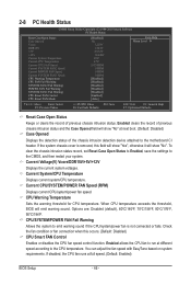
.../+5V/+12V Displays the current system voltages. 2-8 PC Health Status CMOS Setup Utility-Copyright (C) 1984-2010 Award Software PC Health Status Reset Case Open Status Case Opened Vcore DDR15V +5V +12V Current System Temperature Current CPU Temperature Current CPU FAN Speed Current SYSTEM FAN2 Speed Current POWER FAN Speed Current SYSTEM FAN1 Speed CPU Warning Temperature CPU FAN Fail Warning SYSTEM FAN2 Fail Warning POWER FAN Fail Warning SYSTEM FAN1 Fail Warning CPU Smart FAN Control CPU Smart FAN Mode [Disabled] No 1.220V...
.../+5V/+12V Displays the current system voltages. 2-8 PC Health Status CMOS Setup Utility-Copyright (C) 1984-2010 Award Software PC Health Status Reset Case Open Status Case Opened Vcore DDR15V +5V +12V Current System Temperature Current CPU Temperature Current CPU FAN Speed Current SYSTEM FAN2 Speed Current POWER FAN Speed Current SYSTEM FAN1 Speed CPU Warning Temperature CPU FAN Fail Warning SYSTEM FAN2 Fail Warning POWER FAN Fail Warning SYSTEM FAN1 Fail Warning CPU Smart FAN Control CPU Smart FAN Mode [Disabled] No 1.220V...
Manual
Page 59
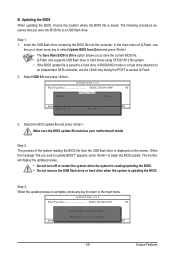
... HDD 0-0 Loa d CMO S Default Enable Update BIOS from the USB flash drive is displayed on the screen. Q-Flash Utility v2.15 Flash Type/Size MXIC 25L8005/8006 1M Keep DMI Data Enable !L! Step 2: The process of Q-Flash, use the up or down arrow key to select Update BIOS from Drive Please SparevsesBaInOySketoy Dtoricvoentinue Enter : Run hi:Move ESC:Reset F10:Power Off - 59 - B. Insert the USB flash drive containing the BIOS file into the computer. Update BIOS from Drive and press . • The Save Main BIOS...
... HDD 0-0 Loa d CMO S Default Enable Update BIOS from the USB flash drive is displayed on the screen. Q-Flash Utility v2.15 Flash Type/Size MXIC 25L8005/8006 1M Keep DMI Data Enable !L! Step 2: The process of Q-Flash, use the up or down arrow key to select Update BIOS from Drive Please SparevsesBaInOySketoy Dtoricvoentinue Enter : Run hi:Move ESC:Reset F10:Power Off - 59 - B. Insert the USB flash drive containing the BIOS file into the computer. Update BIOS from Drive and press . • The Save Main BIOS...
Manual
Page 71
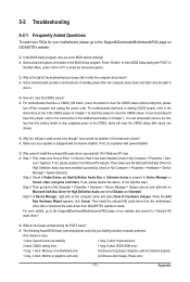
... stop supplying power to the CMOS, which will clear the CMOS values after the computer shuts down ? For more FAQs for your motherboard, please go to the Support&Downloads\Motherboard\FAQ page on GIGABYTE's website. A: The following Award BIOS beep code descriptions may help you identify possible computer problems. (For reference only.) 1 short: System boots successfully 1 long, 3 short: Keyboard error 2 short: CMOS setting error 1 long, 9 short: BIOS ROM error 1 long, 1 short: Memory or motherboard error Continuous long beeps: Graphics card not inserted properly 1 long, 2 short...
... stop supplying power to the CMOS, which will clear the CMOS values after the computer shuts down ? For more FAQs for your motherboard, please go to the Support&Downloads\Motherboard\FAQ page on GIGABYTE's website. A: The following Award BIOS beep code descriptions may help you identify possible computer problems. (For reference only.) 1 short: System boots successfully 1 long, 3 short: Keyboard error 2 short: CMOS setting error 1 long, 9 short: BIOS ROM error 1 long, 1 short: Memory or motherboard error Continuous long beeps: Graphics card not inserted properly 1 long, 2 short...


