Manual
Page 1
GA-P55-S3 LGA1156 socket motherboard for Intel® Core™ i7 processors/ Intel® Core™ i5 processors/Intel® Core™ i3 processors/ Intel® Pentium® processors User's Manual Rev. 1301 12ME-P55S3-1301R
GA-P55-S3 LGA1156 socket motherboard for Intel® Core™ i7 processors/ Intel® Core™ i5 processors/Intel® Core™ i3 processors/ Intel® Pentium® processors User's Manual Rev. 1301 12ME-P55S3-1301R
Manual
Page 2
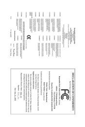
Motherboard GA-P55-S3 Jun. 21, 2010 Motherboard GA-P55-S3 Jun. 21, 2010
Motherboard GA-P55-S3 Jun. 21, 2010 Motherboard GA-P55-S3 Jun. 21, 2010
Manual
Page 3
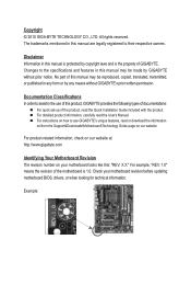
... are legally registered to the specifications and features in this manual may be reproduced, copied, translated, transmitted, or published in the use GIGABYTE's unique features, read the Quick Installation Guide included with the product. Changes to their respective owners. No part of the product, read... is 1.0. Copyright © 2010 GIGA-BYTE TECHNOLOGY CO., LTD. For product-related information, check on our website at: http://www.gigabyte.com Identifying Your Motherboard Revision The revision number on how to assist in any form or by copyright laws and is the property of...
... are legally registered to the specifications and features in this manual may be reproduced, copied, translated, transmitted, or published in the use GIGABYTE's unique features, read the Quick Installation Guide included with the product. Changes to their respective owners. No part of the product, read... is 1.0. Copyright © 2010 GIGA-BYTE TECHNOLOGY CO., LTD. For product-related information, check on our website at: http://www.gigabyte.com Identifying Your Motherboard Revision The revision number on how to assist in any form or by copyright laws and is the property of...
Manual
Page 4
Table of Contents Box Contents...6 Optional Items...6 GA-P55-S3 Motherboard Layout 7 GA-P55-S3 Motherboard Block Diagram 8 Chapter 1 Hardware Installation 9 1-1 Installation Precautions 9 1-2 Product Specifications 10 1-3 Installing the CPU and CPU Cooler 12 1-3-1 Installing the CPU 12 1-3-2 Installing the CPU ...
Table of Contents Box Contents...6 Optional Items...6 GA-P55-S3 Motherboard Layout 7 GA-P55-S3 Motherboard Block Diagram 8 Chapter 1 Hardware Installation 9 1-1 Installation Precautions 9 1-2 Product Specifications 10 1-3 Installing the CPU and CPU Cooler 12 1-3-1 Installing the CPU 12 1-3-2 Installing the CPU ...
Manual
Page 5
Chapter 3 Drivers Installation 51 3-1 Installing Chipset Drivers 51 3-2 Application Software 52 3-3 Technical Manuals 52 3-4 Contact...53 3-5 System...53 3-6 Download Center 54 3-7 New Utilities...54 Chapter 4 Unique Features 55 4-1 Xpress Recovery2 55 4-2 BIOS Update Utilities 58 4-2-1 Updating the BIOS with the Q-Flash Utility 58 4-2-2 Updating the BIOS with the @BIOS Utility 61 4-3 EasyTune 6...62 4-4 Q-Share...63 4-5 Auto Green...64 Chapter 5 Appendix...65 5-1 Configuring Audio Input and Output 65 5-1-1 Configuring 2/4/5.1/7.1-Channel Audio 65 5-1-2 Configuring Microphone ...
Chapter 3 Drivers Installation 51 3-1 Installing Chipset Drivers 51 3-2 Application Software 52 3-3 Technical Manuals 52 3-4 Contact...53 3-5 System...53 3-6 Download Center 54 3-7 New Utilities...54 Chapter 4 Unique Features 55 4-1 Xpress Recovery2 55 4-2 BIOS Update Utilities 58 4-2-1 Updating the BIOS with the Q-Flash Utility 58 4-2-2 Updating the BIOS with the @BIOS Utility 61 4-3 EasyTune 6...62 4-4 Q-Share...63 4-5 Auto Green...64 Chapter 5 Appendix...65 5-1 Configuring Audio Input and Output 65 5-1-1 Configuring 2/4/5.1/7.1-Channel Audio 65 5-1-2 Configuring Microphone ...
Manual
Page 6
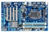
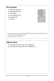
Optional Items 2-port USB 2.0 bracket (Part No. 12CR1-1UB030-5*R) 2-port SATA power cable (Part No. 12CF1-2SERPW-0*R) - 6 - The box contents are for reference only. Box Contents GA-P55-S3 motherboard Motherboard driver disk User's Manual Quick Installation Guide Two SATA cables I/O Shield • The box contents above are subject to change without notice. • The motherboard image is for reference only and the actual items shall depend on the product package you obtain.
Optional Items 2-port USB 2.0 bracket (Part No. 12CR1-1UB030-5*R) 2-port SATA power cable (Part No. 12CF1-2SERPW-0*R) - 6 - The box contents are for reference only. Box Contents GA-P55-S3 motherboard Motherboard driver disk User's Manual Quick Installation Guide Two SATA cables I/O Shield • The box contents above are subject to change without notice. • The motherboard image is for reference only and the actual items shall depend on the product package you obtain.
Manual
Page 7
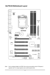
GA-P55-S3 Motherboard Layout KB_MS ATX_12V R_USB_3 LGA1156 R_USB_2 R_USB_1 USB_LAN PWR_FAN ATX AUDIO F_AUDIO Realtek RTL8111E SYS_FAN1 PCIEX1 (Note) PCIEX16 PCI1 CODEC PCI2 PCI3 iTE PCI4 IT8720 PCIEX4 M_BIOS B_BIOS GA-P55-S3 BAT CPU_FAN DDR3_2 DDR3_1 DDR3_4 DDR3_3 SYS_FAN2 F_USB2 Intel® H55 SATA2_0 SATA2_1 SATA2_2 SATA2_5 SATA2_4 SATA2_3 CLR_CMOS F_USB1 F_PANEL (Note) Due to a hardware limitation, the PCIEX1 slot can only accommodate a shorter PCI Express x1 expansion card. For a longer expansion card, use other expansion slots. - 7 -
GA-P55-S3 Motherboard Layout KB_MS ATX_12V R_USB_3 LGA1156 R_USB_2 R_USB_1 USB_LAN PWR_FAN ATX AUDIO F_AUDIO Realtek RTL8111E SYS_FAN1 PCIEX1 (Note) PCIEX16 PCI1 CODEC PCI2 PCI3 iTE PCI4 IT8720 PCIEX4 M_BIOS B_BIOS GA-P55-S3 BAT CPU_FAN DDR3_2 DDR3_1 DDR3_4 DDR3_3 SYS_FAN2 F_USB2 Intel® H55 SATA2_0 SATA2_1 SATA2_2 SATA2_5 SATA2_4 SATA2_3 CLR_CMOS F_USB1 F_PANEL (Note) Due to a hardware limitation, the PCIEX1 slot can only accommodate a shorter PCI Express x1 expansion card. For a longer expansion card, use other expansion slots. - 7 -
Manual
Page 8
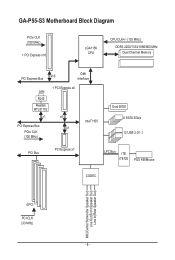
GA-P55-S3 Motherboard Block Diagram PCIe CLK (100 MHz) 1 PCI Express x16 LGA1156 CPU CPU CLK+/- (133 MHz) DDR3 2200/1333/1066/800 MHz Dual Channel Memory PCI Express Bus x16 DMI Interface LAN RJ45 Realtek RTL8111E x1 1 PCI Express x4 x4 PCI Express Bus x1 PCIe CLK (100 MHz) Intel® H55 Dual BIOS 6 SATA 3Gb/s 12 USB 2.0/1.1 PCI Bus PCI Express x1 LPC Bus iTE IT8720 PS/2 KB/Mouse CODEC MIC(Center/Subwoofer Speaker Out) Line Out(Front Speaker Out) Line In(Rear Speaker Out) 4 PCI PCI CLK (33 MHz) - 8 -
GA-P55-S3 Motherboard Block Diagram PCIe CLK (100 MHz) 1 PCI Express x16 LGA1156 CPU CPU CLK+/- (133 MHz) DDR3 2200/1333/1066/800 MHz Dual Channel Memory PCI Express Bus x16 DMI Interface LAN RJ45 Realtek RTL8111E x1 1 PCI Express x4 x4 PCI Express Bus x1 PCIe CLK (100 MHz) Intel® H55 Dual BIOS 6 SATA 3Gb/s 12 USB 2.0/1.1 PCI Bus PCI Express x1 LPC Bus iTE IT8720 PS/2 KB/Mouse CODEC MIC(Center/Subwoofer Speaker Out) Line Out(Front Speaker Out) Line In(Rear Speaker Out) 4 PCI PCI CLK (33 MHz) - 8 -
Manual
Page 9
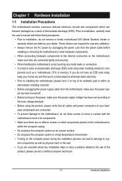
Hardware Installation Chapter 1 Hardware Installation 1-1 Installation Precautions The motherboard contains numerous delicate electronic circuits and components which can lead to damage to system components as well as a result of the product, please consult a certified computer technician. - 9 - Prior to installation, carefully read the user's manual and follow these procedures: • Prior to installation, do not allow screws to come in contact with the motherboard circuit or its components. • Make sure there are no leftover screws or metal components placed on the ...
Hardware Installation Chapter 1 Hardware Installation 1-1 Installation Precautions The motherboard contains numerous delicate electronic circuits and components which can lead to damage to system components as well as a result of the product, please consult a certified computer technician. - 9 - Prior to installation, carefully read the user's manual and follow these procedures: • Prior to installation, do not allow screws to come in contact with the motherboard circuit or its components. • Make sure there are no leftover screws or metal components placed on the ...
Manual
Page 10
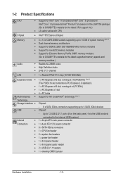
...174; Core™ i5 processors/ Intel® Core™ i3 processors/Intel® Pentium® processors in the LGA1156 package (Go to GIGABYTE's website for the latest CPU support list.) L3 cache varies with CPU Chipset Intel® H55 Express Chipset Memory Audio .../1066/800 MHz memory modules Support for non-ECC memory modules Support for Extreme Memory Profile (XMP) memory modules (Go to GIGABYTE's website for the latest supported memory speeds and memory modules.) Realtek ALC888B codec High Definition Audio 2/4/5.1/7.1-channel LAN 1 ...
...174; Core™ i5 processors/ Intel® Core™ i3 processors/Intel® Pentium® processors in the LGA1156 package (Go to GIGABYTE's website for the latest CPU support list.) L3 cache varies with CPU Chipset Intel® H55 Express Chipset Memory Audio .../1066/800 MHz memory modules Support for non-ECC memory modules Support for Extreme Memory Profile (XMP) memory modules (Go to GIGABYTE's website for the latest supported memory speeds and memory modules.) Realtek ALC888B codec High Definition Audio 2/4/5.1/7.1-channel LAN 1 ...
Manual
Page 11
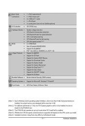
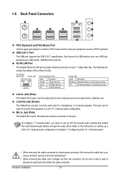
Back Panel Connectors w 1 x PS/2 keyboard port w 1 x PS/2 mouse port w 8 x USB 2.0/1.1 ports w 1 x RJ-45 port w 3 x audio jacks (Line In/Line Out/Microphone) I/O Controller w iTE IT8720 chip Hardware Monitor w w w w w w BIOS w w w w Unique Features w w w w w w w w w w System voltage detection CPU/System temperature detection CPU/System/Power fan speed detection CPU overheating warning CPU/System/Power fan fail warning CPU fan speed control (Note 4) 2 x 8 Mbit flash Use of ...
Back Panel Connectors w 1 x PS/2 keyboard port w 1 x PS/2 mouse port w 8 x USB 2.0/1.1 ports w 1 x RJ-45 port w 3 x audio jacks (Line In/Line Out/Microphone) I/O Controller w iTE IT8720 chip Hardware Monitor w w w w w w BIOS w w w w Unique Features w w w w w w w w w w System voltage detection CPU/System temperature detection CPU/System/Power fan speed detection CPU overheating warning CPU/System/Power fan fail warning CPU fan speed control (Note 4) 2 x 8 Mbit flash Use of ...
Manual
Page 12
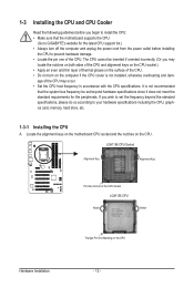
... CPU Notch Notch Triangle Pin One Marking on the computer if the CPU cooler is not recommended that the motherboard supports the CPU. (Go to GIGABYTE's website for the peripherals. The CPU cannot be set the frequency beyond hardware specifications since it does not meet the standard requirements for the latest...
... CPU Notch Notch Triangle Pin One Marking on the computer if the CPU cooler is not recommended that the motherboard supports the CPU. (Go to GIGABYTE's website for the peripherals. The CPU cannot be set the frequency beyond hardware specifications since it does not meet the standard requirements for the latest...
Manual
Page 13
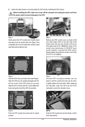
When replacing the load plate, make sure to turn off the computer and unplug the power cord from the socket with the pin one hand to hold the socket lever and use the other to correctly install the CPU into its locked position. Step 5: Push the CPU socket lever back into the motherboard CPU socket. Follow the steps below to lightly replace the load plate. Then completely lift the CPU socket lever and the metal load plate will be lifted as shown. Hardware Installation Hold your index finger down and away from the power outlet to prevent damage to the "REMOVE" mark) ...
When replacing the load plate, make sure to turn off the computer and unplug the power cord from the socket with the pin one hand to hold the socket lever and use the other to correctly install the CPU into its locked position. Step 5: Push the CPU socket lever back into the motherboard CPU socket. Follow the steps below to lightly replace the load plate. Then completely lift the CPU socket lever and the metal load plate will be lifted as shown. Hardware Installation Hold your index finger down and away from the power outlet to prevent damage to the "REMOVE" mark) ...
Manual
Page 14
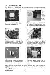
Step 6: Finally, attach the power connector of the CPU cooler to the CPU. Use extreme care when removing the CPU cooler because the thermal grease/tape between the CPU cooler and CPU may damage the CPU. Hardware Installation - 14 - Step 4: You should hear a "click" when pushing down on the surface of the motherboard. Inadequately removing the CPU cooler may adhere to the CPU fan header (CPU_FAN) on installing the cooler.) Step 5: After the installation, check the back of the installed CPU. If the push pin is inserted as the example cooler.) Step 1: Apply an ...
Step 6: Finally, attach the power connector of the CPU cooler to the CPU. Use extreme care when removing the CPU cooler because the thermal grease/tape between the CPU cooler and CPU may damage the CPU. Hardware Installation - 14 - Step 4: You should hear a "click" when pushing down on the surface of the motherboard. Inadequately removing the CPU cooler may adhere to the CPU fan header (CPU_FAN) on installing the cooler.) Step 5: After the installation, check the back of the installed CPU. If the push pin is inserted as the example cooler.) Step 1: Apply an ...
Manual
Page 15
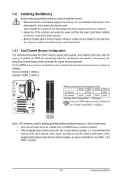
... install it is installed, the BIOS will double the original memory bandwidth. When enabling Dual Channel mode with two memory modules, be used . (Go to GIGABYTE's website for optimum performance. When enabling Dual Channel mode with two or four memory modules, it in the DDR3_1 and DDR3_3 sockets. - 15 - Hardware Installation...
... install it is installed, the BIOS will double the original memory bandwidth. When enabling Dual Channel mode with two memory modules, be used . (Go to GIGABYTE's website for optimum performance. When enabling Dual Channel mode with two or four memory modules, it in the DDR3_1 and DDR3_3 sockets. - 15 - Hardware Installation...

Manual
Page 16
DDR3 and DDR2 DIMMs are not compatible to each other or DDR DIMMs. Be sure to correctly install your fingers on the top edge of the socket will snap into the memory socket. Spread the retaining clips at both ends of the memory module. Step 2: The clips at both ends of the memory, push down on the left, place your memory modules in the memory sockets. Hardware Installation - 16 - As indicated in one direction. Step 1: Note the orientation of the memory socket. Notch DDR3 DIMM A DDR3 memory module has a notch, so it can only fit in the picture on the memory and ...
DDR3 and DDR2 DIMMs are not compatible to each other or DDR DIMMs. Be sure to correctly install your fingers on the top edge of the socket will snap into the memory socket. Spread the retaining clips at both ends of the memory module. Step 2: The clips at both ends of the memory, push down on the left, place your memory modules in the memory sockets. Hardware Installation - 16 - As indicated in one direction. Step 1: Note the orientation of the memory socket. Notch DDR3 DIMM A DDR3 memory module has a notch, so it can only fit in the picture on the memory and ...
Manual
Page 17
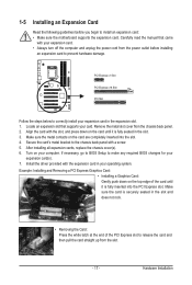
Locate an expansion slot that came with the slot, and press down on the card are completely inserted into the PCI Express slot. Hardware Installation Remove the metal slot cover from the slot. - 17 - Secure the card's metal bracket to the chassis back panel with the expansion card in the slot. 3. Turn on the card until it is fully seated in your computer. Align the card with your card. After installing all expansion cards, replace the chassis cover(s). 6. Install the driver provided with a screw. 5. Make sure the metal contacts on the top edge of the card until...
Locate an expansion slot that came with the slot, and press down on the card are completely inserted into the PCI Express slot. Hardware Installation Remove the metal slot cover from the slot. - 17 - Secure the card's metal bracket to the chassis back panel with the expansion card in the slot. 3. Turn on the card until it is fully seated in your computer. Align the card with your card. After installing all expansion cards, replace the chassis cover(s). 6. Install the driver provided with a screw. 5. Make sure the metal contacts on the top edge of the card until...
Manual
Page 18
Use this port for line in devices such as a USB keyboard/mouse, USB printer, USB flash drive and etc. Connection/ Speed LED Activity LED LAN Port Connection/Speed LED: State Description Orange 1 Gbps data rate Green 100 Mbps data rate Off 10 Mbps data rate Activity LED: State Description Blinking Data transmission or receiving is occurring Off No data transmission or receiving is occurring Line In Jack (Blue) The default line in jack. To configure 7.1-channel audio, you have to connect front speakers in Chapter 5, "Configuring 2/4/5.1/7.1-Channel Audio." • When ...
Use this port for line in devices such as a USB keyboard/mouse, USB printer, USB flash drive and etc. Connection/ Speed LED Activity LED LAN Port Connection/Speed LED: State Description Orange 1 Gbps data rate Green 100 Mbps data rate Off 10 Mbps data rate Activity LED: State Description Blinking Data transmission or receiving is occurring Off No data transmission or receiving is occurring Line In Jack (Blue) The default line in jack. To configure 7.1-channel audio, you have to connect front speakers in Chapter 5, "Configuring 2/4/5.1/7.1-Channel Audio." • When ...

Manual
Page 19
Hardware Installation 1-7 Internal Connectors 1 4 8 10 1) ATX_12V 2) ATX 3) CPU_FAN 4) SYS_FAN1/2 5) PWR_FAN 6) SATA2_0/1/2/3/4/5 5 2 3 4 6 6 7 9 11 7) F_PANEL 8) F_AUDIO 9) F_USB1/F_USB2 10) BAT 11) CLR_CMOS Read the following guidelines before turning on the computer, make sure your computer. Unplug the power cord from the power outlet to prevent damage to the devices. • After installing the device and before connecting external devices: • First make sure the device cable has been securely attached to turn off the devices and your devices are compliant with the ...
Hardware Installation 1-7 Internal Connectors 1 4 8 10 1) ATX_12V 2) ATX 3) CPU_FAN 4) SYS_FAN1/2 5) PWR_FAN 6) SATA2_0/1/2/3/4/5 5 2 3 4 6 6 7 9 11 7) F_PANEL 8) F_AUDIO 9) F_USB1/F_USB2 10) BAT 11) CLR_CMOS Read the following guidelines before turning on the computer, make sure your computer. Unplug the power cord from the power outlet to prevent damage to the devices. • After installing the device and before connecting external devices: • First make sure the device cable has been securely attached to turn off the devices and your devices are compliant with the ...

Manual
Page 20
If a power supply is used that can withstand high power consumption be used (500W or greater). 1/2) ATX_12V/ATX (2x4 12V Power Connector and 2x12 Main Power Connector) With the use of a power supply providing a 2x4 12V power connector is recommended by +5V) 21 +12V 22 +12V (Only for 2x12-pin ATX) 23 3.3V (Only for 2x12-pin ATX) 24 Definition 3.3V -12V GND PS_ON (soft On/Off) GND GND GND -5V +5V +5V +5V (Only for 2x12-pin ATX) GND (Only for 2x12-pin ATX) Hardware Installation - 20 - Connect the power supply cable to the CPU. The 12V power connector mainly supplies power to the ...
If a power supply is used that can withstand high power consumption be used (500W or greater). 1/2) ATX_12V/ATX (2x4 12V Power Connector and 2x12 Main Power Connector) With the use of a power supply providing a 2x4 12V power connector is recommended by +5V) 21 +12V 22 +12V (Only for 2x12-pin ATX) 23 3.3V (Only for 2x12-pin ATX) 24 Definition 3.3V -12V GND PS_ON (soft On/Off) GND GND GND -5V +5V +5V +5V (Only for 2x12-pin ATX) GND (Only for 2x12-pin ATX) Hardware Installation - 20 - Connect the power supply cable to the CPU. The 12V power connector mainly supplies power to the ...
