Manual
Page 1
GA-P41T-D3 LGA775 socket motherboard for Intel® Core™ processor family/ Intel® Pentium® processor family/Intel® Celeron® processor family User's Manual Rev. 1301 12ME-P41TD3-1301R
GA-P41T-D3 LGA775 socket motherboard for Intel® Core™ processor family/ Intel® Pentium® processor family/Intel® Celeron® processor family User's Manual Rev. 1301 12ME-P41TD3-1301R
Manual
Page 3
... laws and is the property of the motherboard is protected by GIGABYTE without GIGABYTE's prior written permission. For product-related information, check on our website at: http://www.gigabyte.com.tw Identifying Your Motherboard Revision The revision number on our website.... : "REV: X.X." Documentation Classifications In order to their respective owners. Check your motherboard looks like this manual may be reproduced, copied, translated, transmitted, or published in the use GIGABYTE's unique features, read the User's Manual. All rights reserved. For example, ...
... laws and is the property of the motherboard is protected by GIGABYTE without GIGABYTE's prior written permission. For product-related information, check on our website at: http://www.gigabyte.com.tw Identifying Your Motherboard Revision The revision number on our website.... : "REV: X.X." Documentation Classifications In order to their respective owners. Check your motherboard looks like this manual may be reproduced, copied, translated, transmitted, or published in the use GIGABYTE's unique features, read the User's Manual. All rights reserved. For example, ...
Manual
Page 4
Table of Contents Box Contents...6 Optional Items...6 GA-P41T-D3 Motherboard Layout 7 GA-P41T-D3 Motherboard Block Diagram 8 Chapter 1 Hardware Installation 9 1-1 Installation Precautions 9 1-2 Product Specifications 10 1-3 Installing the CPU and CPU Cooler 13 1-3-1 Installing the CPU 13 1-3-2 Installing the CPU Cooler ...
Table of Contents Box Contents...6 Optional Items...6 GA-P41T-D3 Motherboard Layout 7 GA-P41T-D3 Motherboard Block Diagram 8 Chapter 1 Hardware Installation 9 1-1 Installation Precautions 9 1-2 Product Specifications 10 1-3 Installing the CPU and CPU Cooler 13 1-3-1 Installing the CPU 13 1-3-2 Installing the CPU Cooler ...
Manual
Page 6
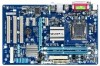
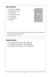
Box Contents GA-P41T-D3 motherboard Motherboard driver disk User's Manual Quick Installation Guide One IDE cable Two SATA cables I/O Shield • The box contents above are subject to change without notice. • The motherboard image is for reference only and the actual items shall depend on the product package you obtain. Optional Items Floppy disk drive cable (Part No. 12CF1-1FD001-7*R) 2-port USB 2.0 bracket (Part No. 12CR1-1UB030-5*R) 2-port SATA power cable (Part No. 12CF1-2SERPW-0*R) - 6 - The box contents are for reference only.
Box Contents GA-P41T-D3 motherboard Motherboard driver disk User's Manual Quick Installation Guide One IDE cable Two SATA cables I/O Shield • The box contents above are subject to change without notice. • The motherboard image is for reference only and the actual items shall depend on the product package you obtain. Optional Items Floppy disk drive cable (Part No. 12CF1-1FD001-7*R) 2-port USB 2.0 bracket (Part No. 12CR1-1UB030-5*R) 2-port SATA power cable (Part No. 12CF1-2SERPW-0*R) - 6 - The box contents are for reference only.
Manual
Page 7
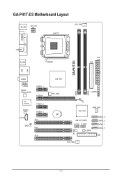
GA-P41T-D3 Motherboard Layout KB_MS ATX_12V LGA775 CPU_FAN COMA LPT LAN COAXIAL R_USB ATX IDE GA-P41T-D3 USB AUDIO F_AUDIO Realtek RTL8111C/D/E PCIEX1_1 PCIEX16 iTE IT8718 PCIEX1_2 CODEC CD_IN PCIEX1_3 PCI1 SPDIF_O PCI2 PCI3 Intel® G41 SYS_FAN1 F_PANEL DDR3_1 DDR3_2 Intel® ICH7 PWR_FAN BAT SATA2_3 CLR_CMOS SATA2_2 F_USB1 F_USB2 SATA2_1 B_BIOS SATA2_0 M_BIOS FDD SYS_FAN2 - 7 -
GA-P41T-D3 Motherboard Layout KB_MS ATX_12V LGA775 CPU_FAN COMA LPT LAN COAXIAL R_USB ATX IDE GA-P41T-D3 USB AUDIO F_AUDIO Realtek RTL8111C/D/E PCIEX1_1 PCIEX16 iTE IT8718 PCIEX1_2 CODEC CD_IN PCIEX1_3 PCI1 SPDIF_O PCI2 PCI3 Intel® G41 SYS_FAN1 F_PANEL DDR3_1 DDR3_2 Intel® ICH7 PWR_FAN BAT SATA2_3 CLR_CMOS SATA2_2 F_USB1 F_USB2 SATA2_1 B_BIOS SATA2_0 M_BIOS FDD SYS_FAN2 - 7 -
Manual
Page 8
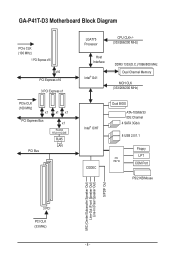
GA-P41T-D3 Motherboard Block Diagram PCIe CLK (100 MHz) 1 PCI Express x16 x16 PCI Express x16 3 PCI Express x1 PCIe CLK (100 MHz) x1 x1 x1 PCI Express ...
GA-P41T-D3 Motherboard Block Diagram PCIe CLK (100 MHz) 1 PCI Express x16 x16 PCI Express x16 3 PCI Express x1 PCIe CLK (100 MHz) x1 x1 x1 PCI Express ...
Manual
Page 9
... computer system on an uneven surface. • Do not place the computer system in a high-temperature environment. • Turning on the motherboard, make sure the power supply voltage has been set according to wear an electrostatic discharge (ESD) wrist strap when handling electronic com- These ...are required for warranty validation. • Always remove the AC power by your hardware components are connected. • To prevent damage to the motherboard, do not have an ESD wrist strap, keep your hands dry and first touch a metal object to eliminate static electricity. • Prior...
... computer system on an uneven surface. • Do not place the computer system in a high-temperature environment. • Turning on the motherboard, make sure the power supply voltage has been set according to wear an electrostatic discharge (ESD) wrist strap when handling electronic com- These ...are required for warranty validation. • Always remove the AC power by your hardware components are connected. • To prevent damage to the motherboard, do not have an ESD wrist strap, keep your hands dry and first touch a metal object to eliminate static electricity. • Prior...
Manual
Page 12
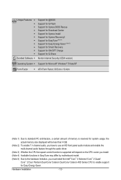
... 3) Whether the CPU fan speed control function is supported will depend on the CPU cooler you install. (Note 4) Available functions in EasyTune may differ by motherboard model. (Note 5) Due to the hardware limitation, you must install the Intel® Core™ 2 Extreme/ Core™ 2 Quad/ Core™ 2 Duo/ Pentium Dual-Core...
... 3) Whether the CPU fan speed control function is supported will depend on the CPU cooler you install. (Note 4) Available functions in EasyTune may differ by motherboard model. (Note 5) Due to the hardware limitation, you must install the Intel® Core™ 2 Extreme/ Core™ 2 Quad/ Core™ 2 Duo/ Pentium Dual-Core...
Manual
Page 13
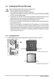
... damage. • Locate the pin one of the CPU. • Do not turn on the computer if the CPU cooler is not recommended that the motherboard supports the CPU. (Go to your hardware specifications including the CPU, graphics card, memory, hard drive, etc. 1-3-1 Installing the CPU A. If you may ... to install the CPU: • Make sure that the system bus frequency be set beyond the standard specifications, please do so according to GIGABYTE's website for the peripherals. LGA775 CPU Socket Alignment Key LGA775 CPU Alignment Key Pin One Corner of the CPU may locate the notches on ...
... damage. • Locate the pin one of the CPU. • Do not turn on the computer if the CPU cooler is not recommended that the motherboard supports the CPU. (Go to your hardware specifications including the CPU, graphics card, memory, hard drive, etc. 1-3-1 Installing the CPU A. If you may ... to install the CPU: • Make sure that the system bus frequency be set beyond the standard specifications, please do so according to GIGABYTE's website for the peripherals. LGA775 CPU Socket Alignment Key LGA775 CPU Alignment Key Pin One Corner of the CPU may locate the notches on ...
Manual
Page 14
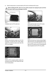
... the CPU. Step 5: Once the CPU is not installed.) Step 4: Hold the CPU with the socket alignment keys) and gently insert the CPU into the motherboard CPU socket. CPU Socket Lever Step 1: Completely raise the CPU socket lever. Hardware Installation - 14 -
... the CPU. Step 5: Once the CPU is not installed.) Step 4: Hold the CPU with the socket alignment keys) and gently insert the CPU into the motherboard CPU socket. CPU Socket Lever Step 1: Completely raise the CPU socket lever. Hardware Installation - 14 -
Manual
Page 15
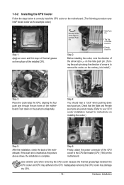
.... (Refer to your CPU cooler installation manual for instructions on the surface of the CPU cooler to the CPU fan header (CPU_FAN) on the motherboard. Use extreme care when removing the CPU cooler because the thermal grease/tape between the CPU cooler and CPU may damage the CPU. - 15 ...- 1-3-2 Installing the CPU Cooler Follow the steps below to correctly install the CPU cooler on the motherboard. (The following procedure uses Intel® boxed cooler as the picture above shows, the installation is to install.) Step 3: Place the cooler atop ...
.... (Refer to your CPU cooler installation manual for instructions on the surface of the CPU cooler to the CPU fan header (CPU_FAN) on the motherboard. Use extreme care when removing the CPU cooler because the thermal grease/tape between the CPU cooler and CPU may damage the CPU. - 15 ...- 1-3-2 Installing the CPU Cooler Follow the steps below to correctly install the CPU cooler on the motherboard. (The following procedure uses Intel® boxed cooler as the picture above shows, the installation is to install.) Step 3: Place the cooler atop ...
Manual
Page 16
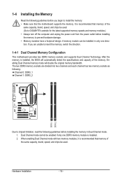
...1: DDR3_2 DDR3_1 DDR3_2 Due to chipset limitation, read the following guidelines before you begin to install the memory: • Make sure that the motherboard supports the memory. The two DDR3 memory sockets are unable to prevent hardware damage. • Memory modules have a foolproof design. Dual Channel ...is installed. 2. After the memory is recommended that memory of the same capacity, brand, speed, and chips be used . (Go to GIGABYTE's website for the latest supported memory speeds and memory modules.) • Always turn off the computer and unplug the power cord from the ...
...1: DDR3_2 DDR3_1 DDR3_2 Due to chipset limitation, read the following guidelines before you begin to install the memory: • Make sure that the motherboard supports the memory. The two DDR3 memory sockets are unable to prevent hardware damage. • Memory modules have a foolproof design. Dual Channel ...is installed. 2. After the memory is recommended that memory of the same capacity, brand, speed, and chips be used . (Go to GIGABYTE's website for the latest supported memory speeds and memory modules.) • Always turn off the computer and unplug the power cord from the ...
Manual
Page 17
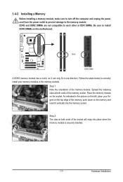
... DIMMs are not compatible to each other or DDR DIMMs. Be sure to install DDR3 DIMMs on the socket. Place the memory module on this motherboard. Spread the retaining clips at both ends of the memory socket.
... DIMMs are not compatible to each other or DDR DIMMs. Be sure to install DDR3 DIMMs on the socket. Place the memory module on this motherboard. Spread the retaining clips at both ends of the memory socket.
Manual
Page 18
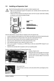
... turn off the computer and unplug the power cord from the power outlet before you begin to install an expansion card: • Make sure the motherboard supports the expansion card. PCI Express x1 Slot PCI Express x16 Slot PCI Slot Follow the steps below to correctly install your expansion card(s). 7. Make...
... turn off the computer and unplug the power cord from the power outlet before you begin to install an expansion card: • Make sure the motherboard supports the expansion card. PCI Express x1 Slot PCI Express x16 Slot PCI Slot Follow the steps below to correctly install your expansion card(s). 7. Make...
Manual
Page 19
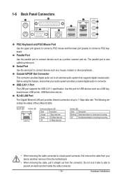
... Connector This connector provides digital audio out to prevent an electrical short inside the cable connector. - 19 - Do not rock it straight out from the motherboard. • When removing the cable, pull it side to side to an external audio system that supports digital coaxial audio. Use this feature, ensure that...
... Connector This connector provides digital audio out to prevent an electrical short inside the cable connector. - 19 - Do not rock it straight out from the motherboard. • When removing the cable, pull it side to side to an external audio system that supports digital coaxial audio. Use this feature, ensure that...
Manual
Page 21
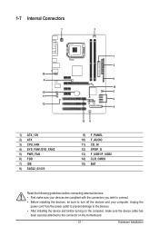
... 8) SATA2_0/1/2/3 7 2 9 14 5 8 6 13 4 9) 10) 11) 12) 13) 14) 15) F_PANEL F_AUDIO CD_IN SPDIF_O F_USB1/F_USB2 CLR_CMOS BAT Read the following guidelines before turning on the motherboard. - 21 - Hardware Installation
... 8) SATA2_0/1/2/3 7 2 9 14 5 8 6 13 4 9) 10) 11) 12) 13) 14) 15) F_PANEL F_AUDIO CD_IN SPDIF_O F_USB1/F_USB2 CLR_CMOS BAT Read the following guidelines before turning on the motherboard. - 21 - Hardware Installation
Manual
Page 22
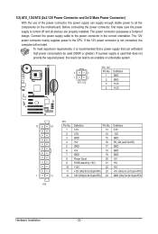
...-pin ATX) Hardware Installation - 22 - The power connector possesses a foolproof design. If the 12V power connector is turned off and all the components on the motherboard. 1/2) ATX_12V/ATX (2x2 12V Power Connector and 2x12 Main Power Connector) With the use of the power connector, the power supply can withstand high power...
...-pin ATX) Hardware Installation - 22 - The power connector possesses a foolproof design. If the 12V power connector is turned off and all the components on the motherboard. 1/2) ATX_12V/ATX (2x2 12V Power Connector and 2x12 Main Power Connector) With the use of the power connector, the power supply can withstand high power...
Manual
Page 23
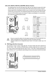
... to connect it is the ground wire). Before connecting a floppy disk drive, be sure to prevent your CPU and system from overheating. The motherboard supports CPU fan speed control, which requires the use of different color. Definition 1 GND 2 +12V 3 Sense PWR_FAN: Pin No. Most...For optimum heat dissipation, it in damage to connect a floppy disk drive. 3/4/5) CPU_FAN/SYS_FAN1/SYS_FAN2/PWR_FAN (Fan Headers) The motherboard has a 4-pin CPU fan header (CPU_FAN), two 3-pin system fan headers (SYS_FAN1 and SYS_FAN2), and a 3-pin power fan header (PWR_FAN). Hardware ...
... to connect it is the ground wire). Before connecting a floppy disk drive, be sure to prevent your CPU and system from overheating. The motherboard supports CPU fan speed control, which requires the use of different color. Definition 1 GND 2 +12V 3 Sense PWR_FAN: Pin No. Most...For optimum heat dissipation, it in damage to connect a floppy disk drive. 3/4/5) CPU_FAN/SYS_FAN1/SYS_FAN2/PWR_FAN (Fan Headers) The motherboard has a 4-pin CPU fan header (CPU_FAN), two 3-pin system fan headers (SYS_FAN1 and SYS_FAN2), and a 3-pin power fan header (PWR_FAN). Hardware ...
Manual
Page 26
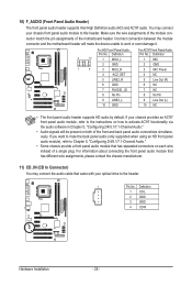
Incorrect connection between the module connector and the motherboard header will be present on both of the front and back panel audio connections simultaneously. For information about connecting the front panel audio module that ... Panel Audio: Pin No. If your chassis provides an AC'97 front panel audio module, refer to the instructions on each wire instead of the motherboard header. If you want to mute the back panel audio (only supported when using an HD front panel audio module), refer to Chapter 5, "Configuring 2/4/5.1/7.1-Channel...
Incorrect connection between the module connector and the motherboard header will be present on both of the front and back panel audio connections simultaneously. For information about connecting the front panel audio module that ... Panel Audio: Pin No. If your chassis provides an AC'97 front panel audio module, refer to the instructions on each wire instead of the motherboard header. If you want to mute the back panel audio (only supported when using an HD front panel audio module), refer to Chapter 5, "Configuring 2/4/5.1/7.1-Channel...
Manual
Page 27
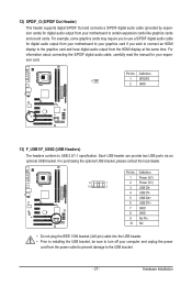
... and connects a S/PDIF digital audio cable (provided by expansion cards) for digital audio output from your motherboard to your graphics card if you to use a S/PDIF digital audio cable for digital audio output from your motherboard to certain expansion cards like graphics cards and sound cards. For information about connecting the S/PDIF...
... and connects a S/PDIF digital audio cable (provided by expansion cards) for digital audio output from your motherboard to your graphics card if you to use a S/PDIF digital audio cable for digital audio output from your motherboard to certain expansion cards like graphics cards and sound cards. For information about connecting the S/PDIF...


