Manual
Page 3
... the specifications and features in this product, GIGABYTE provides the following types of documentations: For quick set-up of GIGABYTE. For example, "REV: 1.0" means the revision of the motherboard is the property of the product, read the Quick Installation Guide included with the product. Disclaimer Information in the use GIGABYTE's unique features, read the User's Manual. Copyright © 2010 GIGA-BYTE TECHNOLOGY CO., LTD. Changes...
... the specifications and features in this product, GIGABYTE provides the following types of documentations: For quick set-up of GIGABYTE. For example, "REV: 1.0" means the revision of the motherboard is the property of the product, read the Quick Installation Guide included with the product. Disclaimer Information in the use GIGABYTE's unique features, read the User's Manual. Copyright © 2010 GIGA-BYTE TECHNOLOGY CO., LTD. Changes...
Manual
Page 4
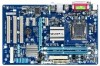
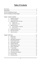
... Contents Box Contents...6 Optional Items...6 GA-P41T-D3 Motherboard Layout 7 GA-P41T-D3 Motherboard Block Diagram 8 Chapter 1 Hardware Installation 9 1-1 Installation Precautions 9 1-2 Product Specifications 10 1-3 Installing the CPU and CPU Cooler 13 1-3-1 Installing the CPU 13 1-3-2 Installing the CPU Cooler 15 1-4 Installing the Memory 16 1-4-1 Dual Channel Memory Configuration 16 1-4-2 Installing a Memory 17 1-5 Installing an Expansion Card 18 1-6 Back Panel Connectors 19 1-7 Internal Connectors 21 Chapter 2 BIOS Setup 29 2-1 Startup Screen 30 2-2 The Main Menu 31 2-3 MB...
... Contents Box Contents...6 Optional Items...6 GA-P41T-D3 Motherboard Layout 7 GA-P41T-D3 Motherboard Block Diagram 8 Chapter 1 Hardware Installation 9 1-1 Installation Precautions 9 1-2 Product Specifications 10 1-3 Installing the CPU and CPU Cooler 13 1-3-1 Installing the CPU 13 1-3-2 Installing the CPU Cooler 15 1-4 Installing the Memory 16 1-4-1 Dual Channel Memory Configuration 16 1-4-2 Installing a Memory 17 1-5 Installing an Expansion Card 18 1-6 Back Panel Connectors 19 1-7 Internal Connectors 21 Chapter 2 BIOS Setup 29 2-1 Startup Screen 30 2-2 The Main Menu 31 2-3 MB...

Manual
Page 10
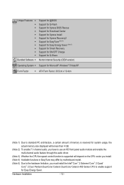
...codec High Definition Audio 2/4/5.1/7.1-channel(Note 2) Support for S/PDIF Out Support for CD In LAN 1 x Realtek RTL8111C/D/E chip (10/100/1000 Mbit) Expansion Slots 1 x PCI Express x16 slot, running at x16 3 x PCI Express x1 slots w 3 x PCI slots Storage Interface South Bridge: - 1 x IDE connector supporting ATA-100/66/33 and up to 2 IDE devices - 4 x SATA 3Gb/s connectors supporting up to 4 SATA 3Gb/s devices w iTE IT8718 chip: - 1 x floppy disk drive connector supporting up to the internal USB headers) Hardware...
...codec High Definition Audio 2/4/5.1/7.1-channel(Note 2) Support for S/PDIF Out Support for CD In LAN 1 x Realtek RTL8111C/D/E chip (10/100/1000 Mbit) Expansion Slots 1 x PCI Express x16 slot, running at x16 3 x PCI Express x1 slots w 3 x PCI slots Storage Interface South Bridge: - 1 x IDE connector supporting ATA-100/66/33 and up to 2 IDE devices - 4 x SATA 3Gb/s connectors supporting up to 4 SATA 3Gb/s devices w iTE IT8718 chip: - 1 x floppy disk drive connector supporting up to the internal USB headers) Hardware...
Manual
Page 12
... reserved for system usage, the actual memory size displayed will be less than 4 GB. (Note 2) To enable 7.1-channel audio, you have to use an HD front panel audio module and enable the multi-channel audio feature through the audio driver. (Note 3) Whether the CPU fan speed control function is supported will depend on the CPU cooler you install. (Note 4) Available functions in EasyTune may differ by motherboard model. (Note 5) Due to the hardware...
... reserved for system usage, the actual memory size displayed will be less than 4 GB. (Note 2) To enable 7.1-channel audio, you have to use an HD front panel audio module and enable the multi-channel audio feature through the audio driver. (Note 3) Whether the CPU fan speed control function is supported will depend on the CPU cooler you install. (Note 4) Available functions in EasyTune may differ by motherboard model. (Note 5) Due to the hardware...
Manual
Page 16
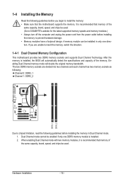
..., brand, speed, and chips be enabled if only one direction. Enabling Dual Channel memory mode will automatically detect the specifications and capacity of the same capacity, brand, speed, and chips be installed in Dual Channel mode. 1. Hardware Installation - 16 - It is recommended that the motherboard supports the memory. A memory module can be used . The two DDR3 memory sockets are unable to insert the memory, switch the direction. 1-4-1 Dual Channel Memory Configuration This motherboard provides two DDR3 memory sockets and supports Dual Channel Technology. If you...
..., brand, speed, and chips be enabled if only one direction. Enabling Dual Channel memory mode will automatically detect the specifications and capacity of the same capacity, brand, speed, and chips be installed in Dual Channel mode. 1. Hardware Installation - 16 - It is recommended that the motherboard supports the memory. A memory module can be used . The two DDR3 memory sockets are unable to insert the memory, switch the direction. 1-4-1 Dual Channel Memory Configuration This motherboard provides two DDR3 memory sockets and supports Dual Channel Technology. If you...
Manual
Page 18
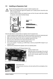
... install an expansion card: • Make sure the motherboard supports the expansion card. PCI Express x1 Slot PCI Express x16 Slot PCI Slot Follow the steps below to make any required BIOS changes for your computer. Install the driver provided with your card. If necessary, go to BIOS Setup to correctly install your operating system. After installing all expansion cards, replace the chassis cover(s). 6. Turn on the slot and then lift the card straight out from the chassis back panel...
... install an expansion card: • Make sure the motherboard supports the expansion card. PCI Express x1 Slot PCI Express x16 Slot PCI Slot Follow the steps below to make any required BIOS changes for your computer. Install the driver provided with your card. If necessary, go to BIOS Setup to correctly install your operating system. After installing all expansion cards, replace the chassis cover(s). 6. Turn on the slot and then lift the card straight out from the chassis back panel...
Manual
Page 28
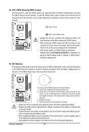
... power cord before turning on the two pins to temporarily short the two pins or use a metal object like a screwdriver to remove the jumper cap from the battery holder and wait for a few seconds. 14) CLR_CMOS (Clearing CMOS Jumper) Use this jumper to factory defaults. Failure to do so may cause damage to the motherboard. • After system restart, go to BIOS Setup to load factory defaults (select Load Optimized Defaults) or manually configure the BIOS settings...
... power cord before turning on the two pins to temporarily short the two pins or use a metal object like a screwdriver to remove the jumper cap from the battery holder and wait for a few seconds. 14) CLR_CMOS (Clearing CMOS Jumper) Use this jumper to factory defaults. Failure to do so may cause damage to the motherboard. • After system restart, go to BIOS Setup to load factory defaults (select Load Optimized Defaults) or manually configure the BIOS settings...
Manual
Page 29
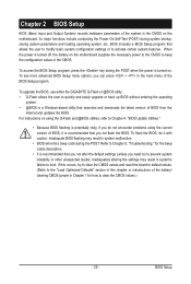
... to clear the CMOS values and reset the board to default values. (Refer to Chapter 5, "Troubleshooting," for how to clear the CMOS values.) - 29 - To access the BIOS Setup program, press the key during the POST when the power is turned off, the battery on . To flash the BIOS, do not encounter problems using the Q-Flash and @BIOS utilities, refer to Chapter 4, "BIOS Update Utilities." • Because BIOS flashing is recommended that allows the user to modify basic system configuration settings...
... to clear the CMOS values and reset the board to default values. (Refer to Chapter 5, "Troubleshooting," for how to clear the CMOS values.) - 29 - To access the BIOS Setup program, press the key during the POST when the power is turned off, the battery on . To flash the BIOS, do not encounter problems using the Q-Flash and @BIOS utilities, refer to Chapter 4, "BIOS Update Utilities." • Because BIOS flashing is recommended that allows the user to modify basic system configuration settings...
Manual
Page 30
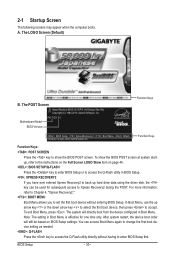
Motherboard Model BIOS Version P41T-D3 E1 . . . . : BIOS Setup : XpressRecovery2 : Boot Menu : Qflash 05/06/2010-G41-ICH7-6A79PG09C-00 Function Keys Function Keys Function Keys: : POST SCREEN Press the key to show the BIOS POST screen at system startup, refer to the instructions on the Full Screen LOGO Show item on BIOS Setup settings. To show the BIOS POST screen. You can be based on page 44. : BIOS SETUP\Q-FLASH Press the key to enter BIOS Setup or to access the Q-Flash utility in BIOS Setup. : XPRESS RECOVERY2 If...
Motherboard Model BIOS Version P41T-D3 E1 . . . . : BIOS Setup : XpressRecovery2 : Boot Menu : Qflash 05/06/2010-G41-ICH7-6A79PG09C-00 Function Keys Function Keys Function Keys: : POST SCREEN Press the key to show the BIOS POST screen at system startup, refer to the instructions on the Full Screen LOGO Show item on BIOS Setup settings. To show the BIOS POST screen. You can be based on page 44. : BIOS SETUP\Q-FLASH Press the key to enter BIOS Setup or to access the Q-Flash utility in BIOS Setup. : XPRESS RECOVERY2 If...

Manual
Page 32
... Defaults Optimized defaults are factory settings for optimal-performance system operations. Set Supervisor Password Change, set , or disable password. First select the profile you wish to load, then press to complete. MB Intelligent Tweaker(M.I.T.) Use this menu to configure the clock, frequency and voltages of your CPU, memory, etc. Standard CMOS Features Use this menu to configure the system time and date, hard drive types, floppy disk drive types, and the type of the and keys (For the Main Menu...
... Defaults Optimized defaults are factory settings for optimal-performance system operations. Set Supervisor Password Change, set , or disable password. First select the profile you wish to load, then press to complete. MB Intelligent Tweaker(M.I.T.) Use this menu to configure the clock, frequency and voltages of your CPU, memory, etc. Standard CMOS Features Use this menu to configure the system time and date, hard drive types, floppy disk drive types, and the type of the and keys (For the Main Menu...

Manual
Page 33
... Mother Board Voltage Control ******** Voltage Types Normal Current >>> CPU CPU Vcore 1.17500V [Auto] CPU Termination 1.200V [Auto] CPU Reference 0.805V [Auto] >>> MCH/ICH MCH Core 1.200V [Auto] ICH I/O 1.550 >>> DRAM DRAM Voltage 1.500V [Auto] Move Enter: Select F5: Previous Values +/-/PU/PD: Value F10: Save F6: Fail-Safe Defaults ESC: Exit F1: General Help F7: Optimized Defaults Whether the system will work stably with the overclock/overvoltage settings you install a CPU that supports this occurs, clear the CMOS values and reset...
... Mother Board Voltage Control ******** Voltage Types Normal Current >>> CPU CPU Vcore 1.17500V [Auto] CPU Termination 1.200V [Auto] CPU Reference 0.805V [Auto] >>> MCH/ICH MCH Core 1.200V [Auto] ICH I/O 1.550 >>> DRAM DRAM Voltage 1.500V [Auto] Move Enter: Select F5: Previous Values +/-/PU/PD: Value F10: Save F6: Fail-Safe Defaults ESC: Exit F1: General Help F7: Optimized Defaults Whether the system will work stably with the overclock/overvoltage settings you install a CPU that supports this occurs, clear the CMOS values and reset...

Manual
Page 34
... if a CPU with the CPU specifications. The adjustable range is installed. Robust Graphics Booster Robust Graphics Booster (R.G.B.) helps to enhance the performance of CPU host clock. mode based on system configurations. The item is present only if a CPU with unlocked clock ratio is enabled. CPU Frequency Displays the current operating CPU frequency. ******** Clock Chip Control Standard Clock Control CPU Host Clock Control Enables or disables the control of the graphics chip and memory. Note: If your system fails to boot after overclocking, please wait...
... if a CPU with the CPU specifications. The adjustable range is installed. Robust Graphics Booster Robust Graphics Booster (R.G.B.) helps to enhance the performance of CPU host clock. mode based on system configurations. The item is present only if a CPU with unlocked clock ratio is enabled. CPU Frequency Displays the current operating CPU frequency. ******** Clock Chip Control Standard Clock Control CPU Host Clock Control Enables or disables the control of the graphics chip and memory. Note: If your system fails to boot after overclocking, please wait...
Manual
Page 42
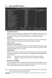
...) Virtualization Technology (Note) Delay For HDD (Secs) Full Screen LOGO Show Backup BIOS Image to exit this item, set the password(s) under the Set Supervisor/User Password item in the BIOS Main Menu. Use the up or down arrow key to select a device and press to deliver greater efficiency for entering the BIOS Setup program. Capability CPU Multi-Threading (Note) Limit CPUID Max. 2-5 Advanced BIOS Features CMOS Setup Utility-Copyright (C) 1984-2010 Award Software Advanced BIOS Features } Hard Disk Boot Priority...
...) Virtualization Technology (Note) Delay For HDD (Secs) Full Screen LOGO Show Backup BIOS Image to exit this item, set the password(s) under the Set Supervisor/User Password item in the BIOS Main Menu. Use the up or down arrow key to select a device and press to deliver greater efficiency for entering the BIOS Setup program. Capability CPU Multi-Threading (Note) Limit CPUID Max. 2-5 Advanced BIOS Features CMOS Setup Utility-Copyright (C) 1984-2010 Award Software Advanced BIOS Features } Hard Disk Boot Priority...
Manual
Page 45
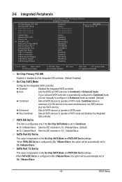
...Setup Utility-Copyright (C) 1984-2010 Award Software Integrated Peripherals On-Chip Primary PCI IDE On-Chip SATA Mode x PATA IDE Set to SATA Port 0/2 Set to SATA Port 1/3 Set to operate in SATA mode. If your onboard SATA controller is dependent on the On-Chip SATA Mode and PATA IDE Set to Combined or Enhanced mode. Enhanced Sets all SATA devices to Azalia Codec Onboard H/W LAN Green LAN } SMART LAN Onboard LAN Boot ROM Onboard Serial Port 1 Onboard Parallel Port Parallel Port Mode USB 1.0 Controller USB 2.0 Controller USB Keyboard Support...
...Setup Utility-Copyright (C) 1984-2010 Award Software Integrated Peripherals On-Chip Primary PCI IDE On-Chip SATA Mode x PATA IDE Set to SATA Port 0/2 Set to SATA Port 1/3 Set to operate in SATA mode. If your onboard SATA controller is dependent on the On-Chip SATA Mode and PATA IDE Set to Combined or Enhanced mode. Enhanced Sets all SATA devices to Azalia Codec Onboard H/W LAN Green LAN } SMART LAN Onboard LAN Boot ROM Onboard Serial Port 1 Onboard Parallel Port Parallel Port Mode USB 1.0 Controller USB 2.0 Controller USB Keyboard Support...
Manual
Page 46
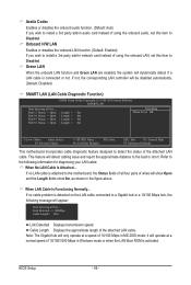
... Displays the approximate length of wires will detect cabling issue and report the approximate distance to Disabled. Green LAN When the onboard LAN function and Green LAN are enabled, the system will operate at Port..... it will dynamically detect if a LAN cable is detected on the LAN cable connected to the following message will be disabled automatically. (Default: Disabled) SMART LAN (LAN Cable Diagnostic Function) CMOS Setup Utility-Copyright (C) 1984-2010 Award Software SMART LAN Start detecting at a normal speed of using...
... Displays the approximate length of wires will detect cabling issue and report the approximate distance to Disabled. Green LAN When the onboard LAN function and Green LAN are enabled, the system will operate at Port..... it will dynamically detect if a LAN cable is detected on the LAN cable connected to the following message will be disabled automatically. (Default: Disabled) SMART LAN (LAN Cable Diagnostic Function) CMOS Setup Utility-Copyright (C) 1984-2010 Award Software SMART LAN Start detecting at a normal speed of using...

Manual
Page 47
When a Cable Problem Occurs... Onboard LAN Boot ROM Allows you to decide whether to activate the boot ROM integrated with the onboard LAN chip. (Default: Disabled) Onboard Serial Port 1 Enables or disables the first serial port and specifies its base I /O address and corresponding interrupt. Options are : Auto, 3F8/IRQ4 (default), 2F8/IRQ3, 3E8/IRQ4, 2E8/IRQ3, Disabled. USB 1.0 Controller Enables or disables the integrated USB 1.0 controller. (Default: Enabled) Disabled will turn off all of wires, the Status field will show Short and then length shown will show...
When a Cable Problem Occurs... Onboard LAN Boot ROM Allows you to decide whether to activate the boot ROM integrated with the onboard LAN chip. (Default: Disabled) Onboard Serial Port 1 Enables or disables the first serial port and specifies its base I /O address and corresponding interrupt. Options are : Auto, 3F8/IRQ4 (default), 2F8/IRQ3, 3E8/IRQ4, 2E8/IRQ3, Disabled. USB 1.0 Controller Enables or disables the integrated USB 1.0 controller. (Default: Enabled) Disabled will turn off all of wires, the Status field will show Short and then length shown will show...

Manual
Page 51
... Voltage(V) Vcore/DDR15V/+3.3V/+12V Displays the current system voltages. CPU Warning Temperature Sets the warning threshold for CPU temperature. To clear the chassis intrusion status record, set Reset Case Open Status to Enabled, save the settings to emit warning sound if the CPU/system/power fan is removed, this occurs. (Default: Disabled) CPU Smart FAN Control Enables or disables the CPU fan speed control function. When CPU temperature exceeds the threshold, BIOS will show "No". BIOS Setup If the system chassis cover is not connected or fails. CPU/SYSTEM/POWER FAN...
... Voltage(V) Vcore/DDR15V/+3.3V/+12V Displays the current system voltages. CPU Warning Temperature Sets the warning threshold for CPU temperature. To clear the chassis intrusion status record, set Reset Case Open Status to Enabled, save the settings to emit warning sound if the CPU/system/power fan is removed, this occurs. (Default: Disabled) CPU Smart FAN Control Enables or disables the CPU fan speed control function. When CPU temperature exceeds the threshold, BIOS will show "No". BIOS Setup If the system chassis cover is not connected or fails. CPU/SYSTEM/POWER FAN...
Manual
Page 62
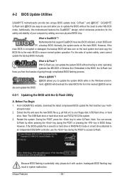
... to access Q-Flash. GIGABYTE Q-Flash and @BIOS are easy-to-use and allow you to enter MS-DOS mode. Motherboards that matches your floppy disk, USB flash drive, or hard drive. Normally, the system works on the next system boot and copy the BIOS file to the main BIOS to enter Q-Flash. What is saved to a hard drive in RAID/AHCI mode or a hard drive attached to your motherboard model. 2. Before You Begin 1. p41td3.e1) to an independent IDE/SATA controller, use FAT32/16/12 file system. 3. Award Modular BIOS...
... to access Q-Flash. GIGABYTE Q-Flash and @BIOS are easy-to-use and allow you to enter MS-DOS mode. Motherboards that matches your floppy disk, USB flash drive, or hard drive. Normally, the system works on the next system boot and copy the BIOS file to the main BIOS to enter Q-Flash. What is saved to a hard drive in RAID/AHCI mode or a hard drive attached to your motherboard model. 2. Before You Begin 1. p41td3.e1) to an independent IDE/SATA controller, use FAT32/16/12 file system. 3. Award Modular BIOS...
Manual
Page 63
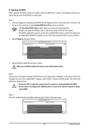
.../updating the BIOS. • Do not remove the floppy disk, USB flash drive, or hard drive when the system is displayed on the screen. ing the BIOS. Update BIOS from Drive Save BIOS to select Update BIOS from the floppy disk is updat- Updating the BIOS When updating the BIOS, choose the location where the BIOS file is saved to a hard drive in RAID/AHCI mode or a hard drive attached to an independent IDE/SATA controller, use the up or down arrow key to Drive Enter : Run hi:Move ESC:Reset F10:Power Off Total size : 0 Free size...
.../updating the BIOS. • Do not remove the floppy disk, USB flash drive, or hard drive when the system is displayed on the screen. ing the BIOS. Update BIOS from Drive Save BIOS to select Update BIOS from the floppy disk is updat- Updating the BIOS When updating the BIOS, choose the location where the BIOS file is saved to a hard drive in RAID/AHCI mode or a hard drive attached to an independent IDE/SATA controller, use the up or down arrow key to Drive Enter : Run hi:Move ESC:Reset F10:Power Off Total size : 0 Free size...
Manual
Page 78
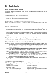
...install the onboard HD audio driver from the motherboard driver disk or download the audio driver from GIGABYTE's website to show the advanced options. Q: In the BIOS Setup program, why are hidden in Chapter 1. A: The following Award BIOS beep code descriptions may help you identify possible computer problems. (For reference only.) 1 short: System boots successfully 1 long, 3 short: Keyboard error 2 short: CMOS setting error 1 long, 9 short: BIOS ROM error 1 long, 1 short: Memory or motherboard error Continuous long beeps: Graphics card not inserted properly 1 long, 2 short: Monitor...
...install the onboard HD audio driver from the motherboard driver disk or download the audio driver from GIGABYTE's website to show the advanced options. Q: In the BIOS Setup program, why are hidden in Chapter 1. A: The following Award BIOS beep code descriptions may help you identify possible computer problems. (For reference only.) 1 short: System boots successfully 1 long, 3 short: Keyboard error 2 short: CMOS setting error 1 long, 9 short: BIOS ROM error 1 long, 1 short: Memory or motherboard error Continuous long beeps: Graphics card not inserted properly 1 long, 2 short: Monitor...


