Manual
Page 1
GA-P35C-DS3R/ GA-P35C-DS3/ GA-P35C-S3 LGA775 socket motherboard for Intel® CoreTM processor family/ Intel® Pentium® processor family/Intel® Celeron® processor family User's Manual Rev. 2002 12ME-P35CDS3R-2002R * The WEEE marking on the product indicates this product must not be disposed of with user's other household waste and must be handed over to a designated collection point for the recycling of waste electrical and electronic equipment!! * The WEEE marking applies only in European Union's member states.
GA-P35C-DS3R/ GA-P35C-DS3/ GA-P35C-S3 LGA775 socket motherboard for Intel® CoreTM processor family/ Intel® Pentium® processor family/Intel® Celeron® processor family User's Manual Rev. 2002 12ME-P35CDS3R-2002R * The WEEE marking on the product indicates this product must not be disposed of with user's other household waste and must be handed over to a designated collection point for the recycling of waste electrical and electronic equipment!! * The WEEE marking applies only in European Union's member states.
Manual
Page 2
Motherboard GA-P35C-DS3R/GA-P35C-DS3/GA-P35C-S3 Jul. 26, 2007 Motherboard GA-P35C-DS3R/GA-P35C-DS3/ GA-P35C-S3 Jul. 26, 2007
Motherboard GA-P35C-DS3R/GA-P35C-DS3/GA-P35C-S3 Jul. 26, 2007 Motherboard GA-P35C-DS3R/GA-P35C-DS3/ GA-P35C-S3 Jul. 26, 2007

Manual
Page 4
Table of Contents Box Contents ...6 OptionalItems ...6 GA-P35C-DS3R/DS3/S3 Motherboard Layout 7 Block Diagram ...8 Chapter 1 Hardware Installation 9 1-1 Installation Precautions 9 1-2 Product Specifications 10 1-3 Installing the CPU and CPU Cooler 13 1-3-1 Installing the CPU 13 1-3-2 Installing the CPU ...
Table of Contents Box Contents ...6 OptionalItems ...6 GA-P35C-DS3R/DS3/S3 Motherboard Layout 7 Block Diagram ...8 Chapter 1 Hardware Installation 9 1-1 Installation Precautions 9 1-2 Product Specifications 10 1-3 Installing the CPU and CPU Cooler 13 1-3-1 Installing the CPU 13 1-3-2 Installing the CPU ...
Manual
Page 6
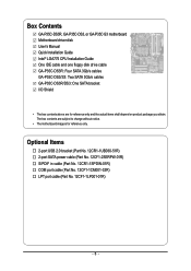
... cable (Part No. 12CF1-1LP001-01R) - 6 - Box Contents GA-P35C-DS3R, GA-P35C-DS3, or GA-P35C-S3 motherboard Motherboard driver disk User's Manual Quick Installation Guide Intel® LGA775 CPU Installation Guide One IDE cable and one floppy disk drive cable GA-P35C-DS3R: Four SATA 3Gb/s cables GA-P35C-DS3/S3: Two SATA 3Gb/s cables GA-P35C-DS3R/DS3: One SATA bracket I/O Shield • The box contents above...
... cable (Part No. 12CF1-1LP001-01R) - 6 - Box Contents GA-P35C-DS3R, GA-P35C-DS3, or GA-P35C-S3 motherboard Motherboard driver disk User's Manual Quick Installation Guide Intel® LGA775 CPU Installation Guide One IDE cable and one floppy disk drive cable GA-P35C-DS3R: Four SATA 3Gb/s cables GA-P35C-DS3/S3: Two SATA 3Gb/s cables GA-P35C-DS3R/DS3: One SATA bracket I/O Shield • The box contents above...

Manual
Page 7
Only for GA-P35C-S3. "*" Only the GA-P35C-DS3R/DS3 adopts All-Solid Capacitor design. - 7 - Only for GA-P35C-DS3. GA-P35C-DS3R/DS3/S3 Motherboard Layout KB_MS ATX_12V CPU_FAN RCA SPDIF LGA775 ATX R_USB1 R_USB2 R_USB3 SYS_FAN2 GA-P35C-DS3R/DS3/S3 USB LAN F_AUDIO ...AUDIO SYS_FAN1 RTL8111B PCIE_3 PCIE_16 CODEC PCIE_1 PCIE_2 SPDIF_O PCI1 SPDIF_I PCI2 IT8718 PCI3 CD_IN COMA Intel® P35 DDRIII2 DDRII3 DDRII4 DDRIII1 DDRII2 DDRII1 FDD PWR_FAN Intel® ICH9R /ICH9 SATAII2 SATAII3 BAT GSATAII0 CLR_CMOS GSATAII1 GIGABYTE...
Only for GA-P35C-S3. "*" Only the GA-P35C-DS3R/DS3 adopts All-Solid Capacitor design. - 7 - Only for GA-P35C-DS3. GA-P35C-DS3R/DS3/S3 Motherboard Layout KB_MS ATX_12V CPU_FAN RCA SPDIF LGA775 ATX R_USB1 R_USB2 R_USB3 SYS_FAN2 GA-P35C-DS3R/DS3/S3 USB LAN F_AUDIO ...AUDIO SYS_FAN1 RTL8111B PCIE_3 PCIE_16 CODEC PCIE_1 PCIE_2 SPDIF_O PCI1 SPDIF_I PCI2 IT8718 PCI3 CD_IN COMA Intel® P35 DDRIII2 DDRII3 DDRII4 DDRIII1 DDRII2 DDRII1 FDD PWR_FAN Intel® ICH9R /ICH9 SATAII2 SATAII3 BAT GSATAII0 CLR_CMOS GSATAII1 GIGABYTE...
Manual
Page 10
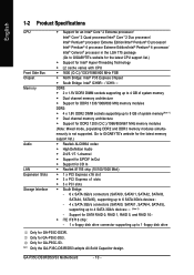
... modules DDR2: Š 4 x 1.8V DDR2 DIMM sockets supporting up to 4 SATA 3Gb/s devices (Note 2) - Only for GA-P35C-DS3. Only for GA-P35C-S3. "*" Only the GA-P35C-DS3R/DS3 adopts All-Solid Capacitor design. Go to GIGABYTE's website for the latest memory support list.) Š Realtek ALC889A codec Š High Definition Audio Š 2/4/5.1/7.1-channel Š Support... iTE IT8718 chip: - 1 x floppy disk drive connector supporting up to 8 GB of system memory(Note 1) Š Dual channel memory architecture Š Support for GA-P35C-DS3R. GA-P35C-DS3R/DS3/S3 Motherboard - 10 -
... modules DDR2: Š 4 x 1.8V DDR2 DIMM sockets supporting up to 4 SATA 3Gb/s devices (Note 2) - Only for GA-P35C-DS3. Only for GA-P35C-S3. "*" Only the GA-P35C-DS3R/DS3 adopts All-Solid Capacitor design. Go to GIGABYTE's website for the latest memory support list.) Š Realtek ALC889A codec Š High Definition Audio Š 2/4/5.1/7.1-channel Š Support... iTE IT8718 chip: - 1 x floppy disk drive connector supporting up to 8 GB of system memory(Note 1) Š Dual channel memory architecture Š Support for GA-P35C-DS3R. GA-P35C-DS3R/DS3/S3 Motherboard - 10 -
Manual
Page 12
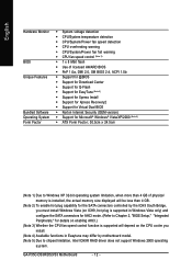
GA-P35C-DS3R/DS3/S3 Motherboard - 12 - English Hardware Monitor BIOS Unique Features Bundled Software Operating System Form Factor Š System voltage detection Š CPU/System temperature detection Š CPU/System/... 3) Whether the CPU fan speed control function is supported will depend on the CPU cooler you install. (Note 4) Available functions in Easytune may differ by motherboard model. (Note 5) Due to chipset limitation, Intel ICH9R RAID driver does not support Windows 2000 operating system.
GA-P35C-DS3R/DS3/S3 Motherboard - 12 - English Hardware Monitor BIOS Unique Features Bundled Software Operating System Form Factor Š System voltage detection Š CPU/System temperature detection Š CPU/System/... 3) Whether the CPU fan speed control function is supported will depend on the CPU cooler you install. (Note 4) Available functions in Easytune may differ by motherboard model. (Note 5) Due to chipset limitation, Intel ICH9R RAID driver does not support Windows 2000 operating system.
Manual
Page 14
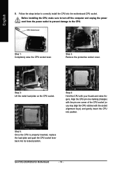
... sure to turn off the computer and unplug the power cord from the power outlet to prevent damage to correctly install the CPU into the motherboard CPU socket. Step 5: Once the CPU is properly inserted, replace the load plate and push the CPU socket lever back into position. Step ... one marking (triangle) with the pin one corner of the CPU socket (or you may align the CPU notches with your thumb and index fingers. GA-P35C-DS3R/DS3/S3 Motherboard - 14 - English B. CPU Socket Lever Step 1: Completely raise the CPU socket lever. Step 4: Hold the CPU with the socket alignment keys) and...
... sure to turn off the computer and unplug the power cord from the power outlet to prevent damage to correctly install the CPU into the motherboard CPU socket. Step 5: Once the CPU is properly inserted, replace the load plate and push the CPU socket lever back into position. Step ... one marking (triangle) with the pin one corner of the CPU socket (or you may align the CPU notches with your thumb and index fingers. GA-P35C-DS3R/DS3/S3 Motherboard - 14 - English B. CPU Socket Lever Step 1: Completely raise the CPU socket lever. Step 4: Hold the CPU with the socket alignment keys) and...
Manual
Page 16
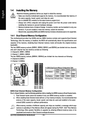
..., and chips be used . (Go to GIGABYTE's website for optimum performance. It is installed, the BIOS will double the original memory bandwidth. After the memory is recommended that the motherboard supports the memory. DS/SS - - GA-P35C-DS3R/DS3/S3 Motherboard - 16 - If you begin to install ... can be used and installed in only one DDR2 memory module is not supported. 1-4-1 Dual Channel Memory Configuration This motherboard provides four DDR2 and two DDR3 memory sockets and supports Dual Channel Technology. Enabling Dual Channel memory mode will automatically detect...
..., and chips be used . (Go to GIGABYTE's website for optimum performance. It is installed, the BIOS will double the original memory bandwidth. After the memory is recommended that the motherboard supports the memory. DS/SS - - GA-P35C-DS3R/DS3/S3 Motherboard - 16 - If you begin to install ... can be used and installed in only one DDR2 memory module is not supported. 1-4-1 Dual Channel Memory Configuration This motherboard provides four DDR2 and two DDR3 memory sockets and supports Dual Channel Technology. Enabling Dual Channel memory mode will automatically detect...
Manual
Page 18
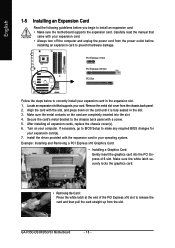
... provided with a screw. 5. Remove the metal slot cover from the slot. If necessary, go to BIOS Setup to prevent hardware damage. GA-P35C-DS3R/DS3/S3 Motherboard - 18 - English 1-5 Installing an Expansion Card Read the following guidelines before installing an expansion card to make any required BIOS changes for your... Express x1 Slot PCI Express x16 Slot PCI Slot Follow the steps below to install an expansion card: • Make sure the motherboard supports the expansion card. Secure the card's metal bracket to release the card and then pull the card straight up from the chassis...
... provided with a screw. 5. Remove the metal slot cover from the slot. If necessary, go to BIOS Setup to prevent hardware damage. GA-P35C-DS3R/DS3/S3 Motherboard - 18 - English 1-5 Installing an Expansion Card Read the following guidelines before installing an expansion card to make any required BIOS changes for your... Express x1 Slot PCI Express x16 Slot PCI Slot Follow the steps below to install an expansion card: • Make sure the motherboard supports the expansion card. Secure the card's metal bracket to release the card and then pull the card straight up from the chassis...

Manual
Page 20
...Gigabit Ethernet LAN port provides Internet connection at up to connect a PS/2 keyboard. The following describes the states of the LAN port LEDs. GA-P35C-DS3R/DS3/S3 Motherboard - 20 - USB Port The USB port supports the USB 2.0/1.1 specification. Before using this port for USB devices such as an USB keyboard/... or receiving is occurring • When removing the cable connected to a back panel connector, first remove the cable from the motherboard. • When removing the cable, pull it side to side to an external audio system that supports digital coaxial audio.
...Gigabit Ethernet LAN port provides Internet connection at up to connect a PS/2 keyboard. The following describes the states of the LAN port LEDs. GA-P35C-DS3R/DS3/S3 Motherboard - 20 - USB Port The USB port supports the USB 2.0/1.1 specification. Before using this port for USB devices such as an USB keyboard/... or receiving is occurring • When removing the cable connected to a back panel connector, first remove the cable from the motherboard. • When removing the cable, pull it side to side to an external audio system that supports digital coaxial audio.
Manual
Page 22
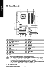
Only for GA-P35C-DS3R. GA-P35C-DS3R/DS3/S3 Motherboard - 22 - English 1-8 Internal Connectors 1 3 4 2 13 6 4 5 20 15 11 9 8 16 7 10 14 18 19 17 21 12 1) ATX_12V 2) ATX (Power Connector) 3) CPU_FAN 4) SYS_FAN1/SYS_FAN2 5) PWR_FAN 6) FDD 7) ... 14) CD_IN 15) SPDIF_O 16) SPDIF_I 17) F_USB1/F_USB2 18) COMA 19) LPT 20) CLR_CMOS 21) CI Read the following guidelines before turning on the motherboard. Unplug the power cord from the power outlet to prevent damage to the devices. • After installing the device and before connecting external devices: •...
Only for GA-P35C-DS3R. GA-P35C-DS3R/DS3/S3 Motherboard - 22 - English 1-8 Internal Connectors 1 3 4 2 13 6 4 5 20 15 11 9 8 16 7 10 14 18 19 17 21 12 1) ATX_12V 2) ATX (Power Connector) 3) CPU_FAN 4) SYS_FAN1/SYS_FAN2 5) PWR_FAN 6) FDD 7) ... 14) CD_IN 15) SPDIF_O 16) SPDIF_I 17) F_USB1/F_USB2 18) COMA 19) LPT 20) CLR_CMOS 21) CI Read the following guidelines before turning on the motherboard. Unplug the power cord from the power outlet to prevent damage to the devices. • After installing the device and before connecting external devices: •...
Manual
Page 24
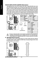
... 2 Speed Control 3 Sense 4 +5V / Speed Control CPU_FAN (For PCB rev. 2.1): Pin No. Do not place a jumper cap on the connector. 34 33 GA-P35C-DS3R/DS3/S3 Motherboard - 24 - 2 1 Definition 1 GND 2 +12V 3 Sense • Be sure to connect fan cables to the fan headers to connect a floppy disk drive....Overheating may hang. • These fan headers are : 360 KB, 720 KB, 1.2 MB, 1.44 MB, and 2.88 MB. The motherboard supports CPU fan speed control, which requires the use of floppy disk drives supported are not configuration jumper blocks. For optimum heat dissipation, it ...
... 2 Speed Control 3 Sense 4 +5V / Speed Control CPU_FAN (For PCB rev. 2.1): Pin No. Do not place a jumper cap on the connector. 34 33 GA-P35C-DS3R/DS3/S3 Motherboard - 24 - 2 1 Definition 1 GND 2 +12V 3 Sense • Be sure to connect fan cables to the fan headers to connect a floppy disk drive....Overheating may hang. • These fan headers are : 360 KB, 720 KB, 1.2 MB, 1.44 MB, and 2.88 MB. The motherboard supports CPU fan speed control, which requires the use of floppy disk drives supported are not configuration jumper blocks. For optimum heat dissipation, it ...
Manual
Page 26
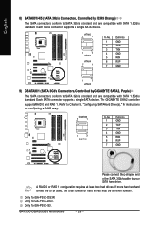
...GIGABYTE SATA2 controller supports RAID 0 and RAID 1. Each SATA connector supports a single SATA device. Refer to be used, the total number of the SATA 3Gb/s cable to SATA 3Gb/s standard and are compatible with SATA 1.5Gb/s standard. A RAID 0 or RAID 1 configuration requires at least two hard drives. GA-P35C-DS3R/DS3/S3 Motherboard - 26 - Only for GA-P35C...-S3. If more than two hard drives are to Chapter 5, "Configuring SATA Hard Drive(s)," for GA-P35C-DS3. GSATAII0 7 1 1 7 ...
...GIGABYTE SATA2 controller supports RAID 0 and RAID 1. Each SATA connector supports a single SATA device. Refer to be used, the total number of the SATA 3Gb/s cable to SATA 3Gb/s standard and are compatible with SATA 1.5Gb/s standard. A RAID 0 or RAID 1 configuration requires at least two hard drives. GA-P35C-DS3R/DS3/S3 Motherboard - 26 - Only for GA-P35C...-S3. If more than two hard drives are to Chapter 5, "Configuring SATA Hard Drive(s)," for GA-P35C-DS3. GSATAII0 7 1 1 7 ...
Manual
Page 28
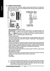
Press the reset switch to restart the computer if the computer freezes and fails to indicate the problem. GA-P35C-DS3R/DS3/S3 Motherboard - 28 - PW+ PWSPEAK+ SPEAK- 2 20 1 19 HD+ HD- If a problem is reading or writing data. • RES (Reset Switch, Green): Connects to the power status ...
Press the reset switch to restart the computer if the computer freezes and fails to indicate the problem. GA-P35C-DS3R/DS3/S3 Motherboard - 28 - PW+ PWSPEAK+ SPEAK- 2 20 1 19 HD+ HD- If a problem is reading or writing data. • RES (Reset Switch, Green): Connects to the power status ...
Manual
Page 30
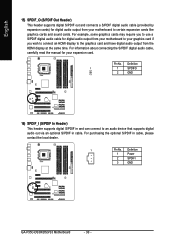
Definition 1 Power 2 SPDIFI 3 GND GA-P35C-DS3R/DS3/S3 Motherboard - 30 - For purchasing the optional S/PDIF in cable. For information about connecting the S/PDIF digital audio cable, carefully read the manual for your graphics card... supports digital S/PDIF out and connects a S/PDIF digital audio cable (provided by expansion cards) for digital audio output from your motherboard to the graphics card and have digital audio output from your motherboard to your expansion card. Pin No. Definition 1 1 SPDIFO 2 GND 16) SPDIF_I (S/PDIF In Header) This header supports digital ...
Definition 1 Power 2 SPDIFI 3 GND GA-P35C-DS3R/DS3/S3 Motherboard - 30 - For purchasing the optional S/PDIF in cable. For information about connecting the S/PDIF digital audio cable, carefully read the manual for your graphics card... supports digital S/PDIF out and connects a S/PDIF digital audio cable (provided by expansion cards) for digital audio output from your motherboard to the graphics card and have digital audio output from your motherboard to your expansion card. Pin No. Definition 1 1 SPDIFO 2 GND 16) SPDIF_I (S/PDIF In Header) This header supports digital ...

Manual
Page 32
... GND PD6 GND PD7 GND ACKGND BUSY GND PE No Pin SLCT GND 20) CLR_CMOS (Clearing CMOS Jumper) Use this jumper to factory defaults. GA-P35C-DS3R/DS3/S3 Motherboard - 32 - date information and BIOS configurations) and reset the CMOS values to clear the CMOS values (e.g. Open: Normal Short: Clear CMOS Values... or use a metal object like a screwdriver to remove the jumper cap from the jumper. Failure to do so may cause damage to the motherboard. • After system restart, go to BIOS Setup to load factory defaults (select Load Optimized Defaults) or manually configure the BIOS settings (...
... GND PD6 GND PD7 GND ACKGND BUSY GND PE No Pin SLCT GND 20) CLR_CMOS (Clearing CMOS Jumper) Use this jumper to factory defaults. GA-P35C-DS3R/DS3/S3 Motherboard - 32 - date information and BIOS configurations) and reset the CMOS values to clear the CMOS values (e.g. Open: Normal Short: Clear CMOS Values... or use a metal object like a screwdriver to remove the jumper cap from the jumper. Failure to do so may cause damage to the motherboard. • After system restart, go to BIOS Setup to load factory defaults (select Load Optimized Defaults) or manually configure the BIOS settings (...
Manual
Page 34
English GA-P35C-DS3R/DS3/S3 Motherboard - 34 -
English GA-P35C-DS3R/DS3/S3 Motherboard - 34 -

Manual
Page 36
...in BIOS Setup. : Xpress Recovery2 If you to set the first boot device without having to accept. GA-P35C-DS3R/DS3/S3 Motherboard - 36 - To show the BIOS POST screen. The POST Screen Motherboard Model BIOS Version Award Modular BIOS v6.00PG, An Energy Star Ally Copyright (C) 1984-2007, Award Software,... > or the down arrow key< > to select the first boot device, then press to enter BIOS Setup first. The system will still be used for P35C-DS3R F4d . . . . : BIOS Setup/Q-Flash : XpressRecovery2 : Boot Menu : Qflash 07/09/2007-P35-ICH9-6A790G0BC-00 Function Keys Function Keys: :...
...in BIOS Setup. : Xpress Recovery2 If you to set the first boot device without having to accept. GA-P35C-DS3R/DS3/S3 Motherboard - 36 - To show the BIOS POST screen. The POST Screen Motherboard Model BIOS Version Award Modular BIOS v6.00PG, An Energy Star Ally Copyright (C) 1984-2007, Award Software,... > or the down arrow key< > to select the first boot device, then press to enter BIOS Setup first. The system will still be used for P35C-DS3R F4d . . . . : BIOS Setup/Q-Flash : XpressRecovery2 : Boot Menu : Qflash 07/09/2007-P35-ICH9-6A790G0BC-00 Function Keys Function Keys: :...

Manual
Page 75
... SATA signal cable to the rear of the GA-P35C-DS3R motherboard. - 75 - If there is set to AHCI or RAID mode. (Note 3) Due to available SATA port on the motherboard. Configure SATA controller mode in RAID BIOS. (Note 1) D. Only the GA-P35C-DS3R supports RAID function. English Chapter 5 Appendix ... want to create RAID array on configurig a RAID array in this chapter are for the SATA ports. (For example, on the GA-P35C-DS3R motherboard, the SATAII0, SATAII1, SATAII2, SATAII3, SATAII4 and SATAII5 ports are supported by the ICH9R Southbridge.) Then connect the power connector from...
... SATA signal cable to the rear of the GA-P35C-DS3R motherboard. - 75 - If there is set to AHCI or RAID mode. (Note 3) Due to available SATA port on the motherboard. Configure SATA controller mode in RAID BIOS. (Note 1) D. Only the GA-P35C-DS3R supports RAID function. English Chapter 5 Appendix ... want to create RAID array on configurig a RAID array in this chapter are for the SATA ports. (For example, on the GA-P35C-DS3R motherboard, the SATAII0, SATAII1, SATAII2, SATAII3, SATAII4 and SATAII5 ports are supported by the ICH9R Southbridge.) Then connect the power connector from...


