
Manual
Page 7
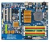
... IT8718 PCI3 CD_IN COMA Intel® P35 DDRIII2 DDRII3 DDRII4 DDRIII1 DDRII2 DDRII1 FDD PWR_FAN Intel® ICH9R /ICH9 SATAII2 SATAII3 BAT GSATAII0 CLR_CMOS GSATAII1 GIGABYTE SATA2 / JMicron 368 BIOS SATAII0 SATAII1 SATAII4 SATAII5 IDE1 CI LPT F_USB2 F_USB1 PWR_LED F_PANEL Only for GA-P35C-DS3. Only for GA-P35C-S3.
... IT8718 PCI3 CD_IN COMA Intel® P35 DDRIII2 DDRII3 DDRII4 DDRIII1 DDRII2 DDRII1 FDD PWR_FAN Intel® ICH9R /ICH9 SATAII2 SATAII3 BAT GSATAII0 CLR_CMOS GSATAII1 GIGABYTE SATA2 / JMicron 368 BIOS SATAII0 SATAII1 SATAII4 SATAII5 IDE1 CI LPT F_USB2 F_USB1 PWR_LED F_PANEL Only for GA-P35C-DS3. Only for GA-P35C-S3.
Manual
Page 8
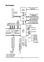
... x16 LAN RJ45 PCIe CLK (100 MHz) Realtek 8111B x1 x1 x1 x1 PCI Express Bus 2 SATA 3Gb/s ATA-133/100/66/ 33 IDE Channel GIGABYTE SATA2 / JMicron 368 PCI Bus LGA775 Processor CPU CLK+/- (400 (O.C.)/333/ 266/200 MHz) Host Interface DDR2 1200 (O.C.)/1066/ 800/667 MHz Intel® Dual... Speaker Out Center/Subwoofer Speaker Out Side Speaker Out MIC Line-Out Line-In SPDIF In SPDIF Out 3 PCI PCI CLK (33 MHz) Only for GA-P35C-S3. - 8 - Only for GA-P35C-DS3R. Only for GA-P35C-DS3.
... x16 LAN RJ45 PCIe CLK (100 MHz) Realtek 8111B x1 x1 x1 x1 PCI Express Bus 2 SATA 3Gb/s ATA-133/100/66/ 33 IDE Channel GIGABYTE SATA2 / JMicron 368 PCI Bus LGA775 Processor CPU CLK+/- (400 (O.C.)/333/ 266/200 MHz) Host Interface DDR2 1200 (O.C.)/1066/ 800/667 MHz Intel® Dual... Speaker Out Center/Subwoofer Speaker Out Side Speaker Out MIC Line-Out Line-In SPDIF In SPDIF Out 3 PCI PCI CLK (33 MHz) Only for GA-P35C-S3. - 8 - Only for GA-P35C-DS3R. Only for GA-P35C-DS3.
Manual
Page 10
... chip: - 1 x floppy disk drive connector supporting up to 4 SATA 3Gb/s devices (Note 2) - Only for GA-P35C-DS3. Go to GIGABYTE's website for the latest memory support list.) Š Realtek ALC889A codec Š High Definition Audio Š 2/4/5.1/7.1-channel ...(Note: Mixed mode, populating DDR2 and DDR3 memory modules simultaneously is not supported. Only for GA-P35C-S3. English 1-2 Product Specifications CPU Front Side Bus Chipset Memory Audio LAN Expansion Slots Storage ... Š Dual channel memory architecture Š Support for GA-P35C-DS3R. GA-P35C-DS3R/DS3/S3 Motherboard - 10 -
... chip: - 1 x floppy disk drive connector supporting up to 4 SATA 3Gb/s devices (Note 2) - Only for GA-P35C-DS3. Go to GIGABYTE's website for the latest memory support list.) Š Realtek ALC889A codec Š High Definition Audio Š 2/4/5.1/7.1-channel ...(Note: Mixed mode, populating DDR2 and DDR3 memory modules simultaneously is not supported. Only for GA-P35C-S3. English 1-2 Product Specifications CPU Front Side Bus Chipset Memory Audio LAN Expansion Slots Storage ... Š Dual channel memory architecture Š Support for GA-P35C-DS3R. GA-P35C-DS3R/DS3/S3 Motherboard - 10 -
Manual
Page 11
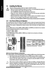
English Storage Interface Š GIGABYTE SATA2 chip : - 1 x IDE connector supporting ATA-133/100/66/33 and up to 2 IDE devices - 2 x SATA 3Gb/s connectors (GSATAII0, GSATAII1), supporting up to 2 IDE devices ... in the South Bridge Š Up to 12 USB 2.0/1.1 ports (8 on the back panel, 4 via the USB brackets connected to 2 SATA 3Gb/s devices) - Only for GA-P35C-DS3. Support for SATA RAID 0, RAID 1, and JBOD Š JMicron 368 chip : - 1 x IDE connector supporting ATA-133/100/66/33 and up to the internal USB...
English Storage Interface Š GIGABYTE SATA2 chip : - 1 x IDE connector supporting ATA-133/100/66/33 and up to 2 IDE devices - 2 x SATA 3Gb/s connectors (GSATAII0, GSATAII1), supporting up to 2 IDE devices ... in the South Bridge Š Up to 12 USB 2.0/1.1 ports (8 on the back panel, 4 via the USB brackets connected to 2 SATA 3Gb/s devices) - Only for GA-P35C-DS3. Support for SATA RAID 0, RAID 1, and JBOD Š JMicron 368 chip : - 1 x IDE connector supporting ATA-133/100/66/33 and up to the internal USB...
Manual
Page 16
... original memory bandwidth. DS/SS - - When memory modules of the same capacity, brand, speed, and chips be used . (Go to GIGABYTE's website for optimum performance. When enabling Dual Channel mode with two or four memory modules, it is recommended that memory of different capacity and chips...DS/SS - - - - It is recommended that the motherboard supports the memory. Dual Channel mode cannot be installed in Dual Channel mode. 1. GA-P35C-DS3R/DS3/S3 Motherboard - 16 - If you begin to install the memory: • Make sure that memory of the memory. DS/SS Four Modules DS/...
... original memory bandwidth. DS/SS - - When memory modules of the same capacity, brand, speed, and chips be used . (Go to GIGABYTE's website for optimum performance. When enabling Dual Channel mode with two or four memory modules, it is recommended that memory of different capacity and chips...DS/SS - - - - It is recommended that the motherboard supports the memory. Dual Channel mode cannot be installed in Dual Channel mode. 1. GA-P35C-DS3R/DS3/S3 Motherboard - 16 - If you begin to install the memory: • Make sure that memory of the memory. DS/SS Four Modules DS/...
Manual
Page 26
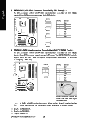
.... Each SATA connector supports a single SATA device. The GIGABYTE SATA2 controller supports RAID 0 and RAID 1. If more than two hard drives are to your SATA hard drive. GA-P35C-DS3R/DS3/S3 Motherboard - 26 - Only for GA-P35C-S3. Only for GA-P35C-DS3. SATAII0 7 1 1 7 SATAII1 SATAII4 7 1 Pin...are compatible with SATA 1.5Gb/s standard. Only for instructions on configuring a RAID array. Refer to Chapter 5, "Configuring SATA Hard Drive(s)," for GA-P35C-DS3R. Each SATA connector supports a single SATA device. GSATAII0 7 1 1 7 GSATAII1 Pin No. 1 2 3 4 5 6 7...
.... Each SATA connector supports a single SATA device. The GIGABYTE SATA2 controller supports RAID 0 and RAID 1. If more than two hard drives are to your SATA hard drive. GA-P35C-DS3R/DS3/S3 Motherboard - 26 - Only for GA-P35C-S3. Only for GA-P35C-DS3. SATAII0 7 1 1 7 SATAII1 SATAII4 7 1 Pin...are compatible with SATA 1.5Gb/s standard. Only for instructions on configuring a RAID array. Refer to Chapter 5, "Configuring SATA Hard Drive(s)," for GA-P35C-DS3R. Each SATA connector supports a single SATA device. GSATAII0 7 1 1 7 GSATAII1 Pin No. 1 2 3 4 5 6 7...

Manual
Page 42
... CPU voltage and core frequency to display the GIGABYTE Logo at system startup. Disabled displays normal POST message. (Default: Enabled) Init Display First Specifies the first initiation of the monitor display from the installed PCI graphics card or the PCI Express graphics card. GA-P35C-DS3R/DS3/S3 Motherboard - 42 - For more information about...
... CPU voltage and core frequency to display the GIGABYTE Logo at system startup. Disabled displays normal POST message. (Default: Enabled) Init Display First Specifies the first initiation of the monitor display from the installed PCI graphics card or the PCI Express graphics card. GA-P35C-DS3R/DS3/S3 Motherboard - 42 - For more information about...
Manual
Page 46
... are : 378/IRQ7 (default), 278/IRQ5, 3BC/IRQ7, Disabled. Only for GA-P35C-DS3. English Onboard LAN Boot ROM Allows you to decide whether to activate the boot ROM integrated with the onboard LAN chip. (Default: Disabled) Onboard SATA/IDE Device (GIGABYTE SATA2 Chip) Enables or disables the IDE and SATA controllers integrated in...
... are : 378/IRQ7 (default), 278/IRQ5, 3BC/IRQ7, Disabled. Only for GA-P35C-DS3. English Onboard LAN Boot ROM Allows you to decide whether to activate the boot ROM integrated with the onboard LAN chip. (Default: Disabled) Onboard SATA/IDE Device (GIGABYTE SATA2 Chip) Enables or disables the IDE and SATA controllers integrated in...

Manual
Page 60
You may press the Install button following an item to install it. 3-3 Driver CD Information This page provides information about the drivers, applications and tools in this driver disk. GA-P35C-DS3R/DS3/S3 Motherboard - 60 - English 3-2 Software Applications This page displays all the tools and applications that GIGABYTE develops and some free software.
You may press the Install button following an item to install it. 3-3 Driver CD Information This page provides information about the drivers, applications and tools in this driver disk. GA-P35C-DS3R/DS3/S3 Motherboard - 60 - English 3-2 Software Applications This page displays all the tools and applications that GIGABYTE develops and some free software.
Manual
Page 68
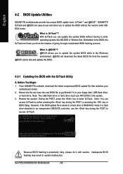
...flashing is @BIOSTM? @BIOS allows you from the nearest @BIOS server site and update the BIOS. 4-2-1 Updating the BIOS with caution. GIGABYTE Q-Flash and @BIOS are easy-to-use and allow you can access Q-Flash by either pressing the key during the POST to your ... Utilities GIGABYTE motherboards provide two unique BIOS update tools, Q-FlashTM and @BIOSTM. With Q-Flash you to update the BIOS without having to update the system BIOS while in BIOS Setup. Award Modular BIOS v6.00PG, An Energy Star Ally Copyright (C) 1984-2007, Award Software, Inc. GA-P35C-DS3R/DS3/S3 ...
...flashing is @BIOSTM? @BIOS allows you from the nearest @BIOS server site and update the BIOS. 4-2-1 Updating the BIOS with caution. GIGABYTE Q-Flash and @BIOS are easy-to-use and allow you can access Q-Flash by either pressing the key during the POST to your ... Utilities GIGABYTE motherboards provide two unique BIOS update tools, Q-FlashTM and @BIOSTM. With Q-Flash you to update the BIOS without having to update the system BIOS while in BIOS Setup. Award Modular BIOS v6.00PG, An Energy Star Ally Copyright (C) 1984-2007, Award Software, Inc. GA-P35C-DS3R/DS3/S3 ...
Manual
Page 72
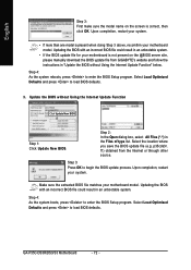
.... Select the location where you save the BIOS update file (e.g. f1) obtained from GIGABYTE's website and follow the instructions in "Update the BIOS without Using the Internet Update Function Click Update New BIOS Step 1: Click Update New BIOS. GA-P35C-DS3R/DS3/S3 Motherboard - 72 - Update the BIOS without Using the Internet Update Function...
.... Select the location where you save the BIOS update file (e.g. f1) obtained from GIGABYTE's website and follow the instructions in "Update the BIOS without Using the Internet Update Function Click Update New BIOS Step 1: Click Update New BIOS. GA-P35C-DS3R/DS3/S3 Motherboard - 72 - Update the BIOS without Using the Internet Update Function...

Manual
Page 82
English C. Configuring a RAID array in the Hard Disk Drive List block and press to configure a RAID array. GA-P35C-DS3R/DS3/S3 Motherboard - 82 - GIGABYTE Technology Corp. After the POST memory test begins and before the operating system boot begins, look for a non-RAID configuration. PCIE-to...Enter the RAID BIOS setup utility to see detailed information about the selected hard drive. Skip this step and proceed to the installation of the GIGABYTE SATA2 RAID BIOS utility (Figure 3), use the up or down arrow key to enter RAID Setup Utility ... Press + to -SATAII/IDE ...
English C. Configuring a RAID array in the Hard Disk Drive List block and press to configure a RAID array. GA-P35C-DS3R/DS3/S3 Motherboard - 82 - GIGABYTE Technology Corp. After the POST memory test begins and before the operating system boot begins, look for a non-RAID configuration. PCIE-to...Enter the RAID BIOS setup utility to see detailed information about the selected hard drive. Skip this step and proceed to the installation of the GIGABYTE SATA2 RAID BIOS utility (Figure 3), use the up or down arrow key to enter RAID Setup Utility ... Press + to -SATAII/IDE ...

Manual
Page 84
...0 only): Under the Block item, use the up or down arrow key to select the stripe block size (Figure 6), ranging from /to abort. GIGABYTE Technology Corp. Set Array Size: Under the Size item, enter the size of the items above are typical values: RAID 0-128KB [KL]-Switch RAID Block...ALL DATA ON THE SELECTED HARD DISK WILL BE LOST WHEN EXIT WITH SAVING [KL]-Switch Unit [DEL,BS]-Delete Number Figure 7 [ENTER]-Next GA-P35C-DS3R/DS3/S3 Motherboard - 84 - [ESC]-Abort The following are configured, the selection bar automatically jumps to the Confirm Creation item. When prompted to ...
...0 only): Under the Block item, use the up or down arrow key to select the stripe block size (Figure 6), ranging from /to abort. GIGABYTE Technology Corp. Set Array Size: Under the Size item, enter the size of the items above are typical values: RAID 0-128KB [KL]-Switch RAID Block...ALL DATA ON THE SELECTED HARD DISK WILL BE LOST WHEN EXIT WITH SAVING [KL]-Switch Unit [DEL,BS]-Delete Number Figure 7 [ENTER]-Next GA-P35C-DS3R/DS3/S3 Motherboard - 84 - [ESC]-Abort The following are configured, the selection bar automatically jumps to the Confirm Creation item. When prompted to ...

Manual
Page 86
GIGABYTE Technology Corp. Delete the RAID Array: To delete the array, select Delete RAID Disk Drive in the main screen to Non-RAID Solve Mirror Conflict ...!! N RAID Level Capacity Status 0-Stripe 240 GB Normal Members(HDDx) 01 [KL]-Select RAID [SPACE]-Mark Delete [DEL]-Confirm Figure 11 GA-P35C-DS3R/DS3/S3 Motherboard - 86 - [ESC]-Abort Press . GIGABYTE Technology Corp. Press the space bar on the array to create the SATA RAID/AHCI driver diskette and the installation of the...
GIGABYTE Technology Corp. Delete the RAID Array: To delete the array, select Delete RAID Disk Drive in the main screen to Non-RAID Solve Mirror Conflict ...!! N RAID Level Capacity Status 0-Stripe 240 GB Normal Members(HDDx) 01 [KL]-Select RAID [SPACE]-Mark Delete [DEL]-Confirm Figure 11 GA-P35C-DS3R/DS3/S3 Motherboard - 86 - [ESC]-Abort Press . GIGABYTE Technology Corp. Press the space bar on the array to create the SATA RAID/AHCI driver diskette and the installation of the...

Manual
Page 90
...list, or press ESC to return to continue the driver installation from the motherboard driver disk. S=Specify Additional Device ENTER=Continue F3=Exit Figure 6 GA-P35C-DS3R/DS3/S3 Motherboard - 90 - Use the arrow keys to configure a SCSI Adapter for use with Windows, using a device support disk provided by ...the floppy disk. If you set the Onboard SATA/IDE Ctrl Mode item in BIOS Setup to RAID mode, select GIGABYTE GBB363 RAID Controller (Windows 2K/XP/2003). (Select GIGABYTE GBB363 AHCI Controller (Windows 2K/XP/2003) for AHCI mode.) Windows Setup You have any device support disks from...
...list, or press ESC to return to continue the driver installation from the motherboard driver disk. S=Specify Additional Device ENTER=Continue F3=Exit Figure 6 GA-P35C-DS3R/DS3/S3 Motherboard - 90 - Use the arrow keys to configure a SCSI Adapter for use with Windows, using a device support disk provided by ...the floppy disk. If you set the Onboard SATA/IDE Ctrl Mode item in BIOS Setup to RAID mode, select GIGABYTE GBB363 RAID Controller (Windows 2K/XP/2003). (Select GIGABYTE GBB363 AHCI Controller (Windows 2K/XP/2003) for AHCI mode.) Windows Setup You have any device support disks from...

Manual
Page 94
English GIGABYTE SATA2 SATA Controller: Step 1: Restart your floppy disk (Figure 13). Figure 12 Step 2: Specify the location where the driver is saved, such as your system to that below appears (RAID/AHCI hard drive(s) will not be detected at this stage), select Load Driver. (Figure 12). Figure 13 GA-P35C-DS3R/DS3/S3 Motherboard - 94 - When a screen similar to boot from the Windows Vista setup disk and perform standard OS installation steps.
English GIGABYTE SATA2 SATA Controller: Step 1: Restart your floppy disk (Figure 13). Figure 12 Step 2: Specify the location where the driver is saved, such as your system to that below appears (RAID/AHCI hard drive(s) will not be detected at this stage), select Load Driver. (Figure 12). Figure 13 GA-P35C-DS3R/DS3/S3 Motherboard - 94 - When a screen similar to boot from the Windows Vista setup disk and perform standard OS installation steps.


