Manual
Page 1
GA-P35C-DS3R/ GA-P35C-DS3/ GA-P35C-S3 LGA775 socket motherboard for Intel® CoreTM processor family/ Intel® Pentium® processor family/Intel® Celeron® processor family User's Manual Rev. 2002 12ME-P35CDS3R-2002R * The WEEE marking on the product indicates this product must not be disposed of with user's other household waste and must be handed over to a designated collection point for the recycling of waste electrical and electronic equipment!! * The WEEE marking applies only in European Union's member states.
GA-P35C-DS3R/ GA-P35C-DS3/ GA-P35C-S3 LGA775 socket motherboard for Intel® CoreTM processor family/ Intel® Pentium® processor family/Intel® Celeron® processor family User's Manual Rev. 2002 12ME-P35CDS3R-2002R * The WEEE marking on the product indicates this product must not be disposed of with user's other household waste and must be handed over to a designated collection point for the recycling of waste electrical and electronic equipment!! * The WEEE marking applies only in European Union's member states.
Manual
Page 2
Motherboard GA-P35C-DS3R/GA-P35C-DS3/GA-P35C-S3 Jul. 26, 2007 Motherboard GA-P35C-DS3R/GA-P35C-DS3/ GA-P35C-S3 Jul. 26, 2007
Motherboard GA-P35C-DS3R/GA-P35C-DS3/GA-P35C-S3 Jul. 26, 2007 Motherboard GA-P35C-DS3R/GA-P35C-DS3/ GA-P35C-S3 Jul. 26, 2007

Manual
Page 4
Table of Contents Box Contents ...6 OptionalItems ...6 GA-P35C-DS3R/DS3/S3 Motherboard Layout 7 Block Diagram ...8 Chapter 1 Hardware Installation 9 1-1 Installation Precautions 9 1-2 Product Specifications 10 1-3 Installing the CPU and CPU Cooler 13 1-3-1 Installing the CPU 13 1-3-2 Installing the ...
Table of Contents Box Contents ...6 OptionalItems ...6 GA-P35C-DS3R/DS3/S3 Motherboard Layout 7 Block Diagram ...8 Chapter 1 Hardware Installation 9 1-1 Installation Precautions 9 1-2 Product Specifications 10 1-3 Installing the CPU and CPU Cooler 13 1-3-1 Installing the CPU 13 1-3-2 Installing the ...
Manual
Page 6
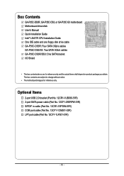
... User's Manual Quick Installation Guide Intel® LGA775 CPU Installation Guide One IDE cable and one floppy disk drive cable GA-P35C-DS3R: Four SATA 3Gb/s cables GA-P35C-DS3/S3: Two SATA 3Gb/s cables GA-P35C-DS3R/DS3: One SATA bracket I/O Shield • The box contents above are subject to change without notice. • The motherboard image is...
... User's Manual Quick Installation Guide Intel® LGA775 CPU Installation Guide One IDE cable and one floppy disk drive cable GA-P35C-DS3R: Four SATA 3Gb/s cables GA-P35C-DS3/S3: Two SATA 3Gb/s cables GA-P35C-DS3R/DS3: One SATA bracket I/O Shield • The box contents above are subject to change without notice. • The motherboard image is...

Manual
Page 7
... ATX R_USB1 R_USB2 R_USB3 SYS_FAN2 GA-P35C-DS3R/DS3/S3 USB LAN F_AUDIO AUDIO SYS_FAN1 RTL8111B PCIE_3 PCIE_16 CODEC PCIE_1 PCIE_2 SPDIF_O PCI1 SPDIF_I PCI2 IT8718 PCI3 CD_IN COMA Intel® P35 DDRIII2 DDRII3 DDRII4 DDRIII1 DDRII2 DDRII1 FDD PWR_FAN Intel® ICH9R /ICH9 SATAII2 SATAII3 BAT GSATAII0 CLR_CMOS GSATAII1 GIGABYTE SATA2 / JMicron 368 BIOS...
... ATX R_USB1 R_USB2 R_USB3 SYS_FAN2 GA-P35C-DS3R/DS3/S3 USB LAN F_AUDIO AUDIO SYS_FAN1 RTL8111B PCIE_3 PCIE_16 CODEC PCIE_1 PCIE_2 SPDIF_O PCI1 SPDIF_I PCI2 IT8718 PCI3 CD_IN COMA Intel® P35 DDRIII2 DDRII3 DDRII4 DDRIII1 DDRII2 DDRII1 FDD PWR_FAN Intel® ICH9R /ICH9 SATAII2 SATAII3 BAT GSATAII0 CLR_CMOS GSATAII1 GIGABYTE SATA2 / JMicron 368 BIOS...
Manual
Page 8
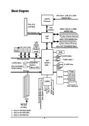
... x16 LAN RJ45 PCIe CLK (100 MHz) Realtek 8111B x1 x1 x1 x1 PCI Express Bus 2 SATA 3Gb/s ATA-133/100/66/ 33 IDE Channel GIGABYTE SATA2 / JMicron 368 PCI Bus LGA775 Processor CPU CLK+/- (400 (O.C.)/333/ 266/200 MHz) Host Interface DDR2 1200 (O.C.)/1066/ 800/667 MHz Intel® Dual... Speaker Out Center/Subwoofer Speaker Out Side Speaker Out MIC Line-Out Line-In SPDIF In SPDIF Out 3 PCI PCI CLK (33 MHz) Only for GA-P35C-DS3. Only for GA-P35C-DS3R. Only for GA-P35C-S3. - 8 -
... x16 LAN RJ45 PCIe CLK (100 MHz) Realtek 8111B x1 x1 x1 x1 PCI Express Bus 2 SATA 3Gb/s ATA-133/100/66/ 33 IDE Channel GIGABYTE SATA2 / JMicron 368 PCI Bus LGA775 Processor CPU CLK+/- (400 (O.C.)/333/ 266/200 MHz) Host Interface DDR2 1200 (O.C.)/1066/ 800/667 MHz Intel® Dual... Speaker Out Center/Subwoofer Speaker Out Side Speaker Out MIC Line-Out Line-In SPDIF In SPDIF Out 3 PCI PCI CLK (33 MHz) Only for GA-P35C-DS3. Only for GA-P35C-DS3R. Only for GA-P35C-S3. - 8 -
Manual
Page 10
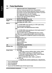
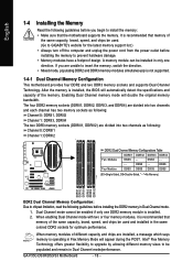
Go to GIGABYTE's website for the latest memory support list.) Š Realtek ALC889A codec Š High Definition Audio Š 2/4/5.1/7.1-channel Š Support for S/PDIF In/Out Š Support for GA-P35C-S3. Only for CD In Š Realtek 8111B chip (10/100/1000 Mbit) Š 1 x PCI Express...DDR2 DIMM sockets supporting up to 8 GB of system memory(Note 1) Š Dual channel memory architecture Š Support for GA-P35C-DS3. "*" Only the GA-P35C-DS3R/DS3 adopts All-Solid Capacitor design. Only for DDR2 1200 (O.C.)/1066/800/667 MHz memory modules (Note: Mixed mode, populating DDR2 ...
Go to GIGABYTE's website for the latest memory support list.) Š Realtek ALC889A codec Š High Definition Audio Š 2/4/5.1/7.1-channel Š Support for S/PDIF In/Out Š Support for GA-P35C-S3. Only for CD In Š Realtek 8111B chip (10/100/1000 Mbit) Š 1 x PCI Express...DDR2 DIMM sockets supporting up to 8 GB of system memory(Note 1) Š Dual channel memory architecture Š Support for GA-P35C-DS3. "*" Only the GA-P35C-DS3R/DS3 adopts All-Solid Capacitor design. Only for DDR2 1200 (O.C.)/1066/800/667 MHz memory modules (Note: Mixed mode, populating DDR2 ...
Manual
Page 11
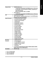
Only for GA-P35C-DS3. English Storage Interface Š GIGABYTE SATA2 chip : - 1 x IDE connector supporting ATA-133/100/66/33 and up to 2 IDE devices - 2 x SATA 3Gb/s connectors... Up to 12 USB 2.0/1.1 ports (8 on the back panel, 4 via the USB brackets connected to 2 SATA 3Gb/s devices) - Hardware Installation Only for GA-P35C-S3. - 11 - Support for SATA RAID 0, RAID 1, and JBOD Š JMicron 368 chip : - 1 x IDE connector supporting ATA-133/100/66.../Rear Speaker Out/Side Speaker Out/Line In/Line Out/Microphone) I/O Controller Š iTE IT8718 chip Only for GA-P35C-DS3R.
Only for GA-P35C-DS3. English Storage Interface Š GIGABYTE SATA2 chip : - 1 x IDE connector supporting ATA-133/100/66/33 and up to 2 IDE devices - 2 x SATA 3Gb/s connectors... Up to 12 USB 2.0/1.1 ports (8 on the back panel, 4 via the USB brackets connected to 2 SATA 3Gb/s devices) - Hardware Installation Only for GA-P35C-S3. - 11 - Support for SATA RAID 0, RAID 1, and JBOD Š JMicron 368 chip : - 1 x IDE connector supporting ATA-133/100/66.../Rear Speaker Out/Side Speaker Out/Line In/Line Out/Microphone) I/O Controller Š iTE IT8718 chip Only for GA-P35C-DS3R.
Manual
Page 12
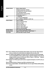
GA-P35C-DS3R/DS3/S3 Motherboard - 12 - English Hardware Monitor BIOS Unique Features Bundled Software Operating System Form Factor Š System voltage detection Š CPU/System temperature detection Š CPU/...
GA-P35C-DS3R/DS3/S3 Motherboard - 12 - English Hardware Monitor BIOS Unique Features Bundled Software Operating System Form Factor Š System voltage detection Š CPU/System temperature detection Š CPU/...
Manual
Page 14
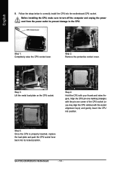
CPU Socket Lever Step 1: Completely raise the CPU socket lever. Step 3: Lift the metal load plate on the CPU socket. GA-P35C-DS3R/DS3/S3 Motherboard - 14 - Step 2: Remove the protective socket cover. English B. Step 5: Once the CPU is properly inserted, replace the load plate and push the CPU socket ...
CPU Socket Lever Step 1: Completely raise the CPU socket lever. Step 3: Lift the metal load plate on the CPU socket. GA-P35C-DS3R/DS3/S3 Motherboard - 14 - Step 2: Remove the protective socket cover. English B. Step 5: Once the CPU is properly inserted, replace the load plate and push the CPU socket ...
Manual
Page 16
... by allowing different memory sizes to be enabled if only one direction. If you begin to GIGABYTE's website for optimum performance. Dual Channel mode cannot be populated and remain in Dual Channel mode/performance. GA-P35C-DS3R/DS3/S3 Motherboard - 16 - English 1-4 Installing the Memory Read the following guidelines before installing the DDR2 memory in...
... by allowing different memory sizes to be enabled if only one direction. If you begin to GIGABYTE's website for optimum performance. Dual Channel mode cannot be populated and remain in Dual Channel mode/performance. GA-P35C-DS3R/DS3/S3 Motherboard - 16 - English 1-4 Installing the Memory Read the following guidelines before installing the DDR2 memory in...
Manual
Page 18
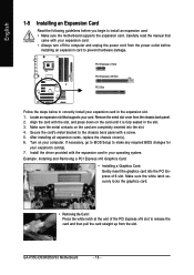
... the chassis cover(s). 6. Install the driver provided with a screw. 5. If necessary, go to BIOS Setup to make any required BIOS changes for your operating system. GA-P35C-DS3R/DS3/S3 Motherboard - 18 - Secure the card's metal bracket to install an expansion card: • Make sure the motherboard supports the expansion card. English 1-5 Installing an...
... the chassis cover(s). 6. Install the driver provided with a screw. 5. If necessary, go to BIOS Setup to make any required BIOS changes for your operating system. GA-P35C-DS3R/DS3/S3 Motherboard - 18 - Secure the card's metal bracket to install an expansion card: • Make sure the motherboard supports the expansion card. English 1-5 Installing an...

Manual
Page 20
The following describes the states of the LAN port LEDs. Do not rock it straight out from the connector. GA-P35C-DS3R/DS3/S3 Motherboard - 20 - Use this feature, ensure that your audio system provides a coaxial digital audio in connector. RJ-45 LAN Port The Gigabit Ethernet LAN port ...
The following describes the states of the LAN port LEDs. Do not rock it straight out from the connector. GA-P35C-DS3R/DS3/S3 Motherboard - 20 - Use this feature, ensure that your audio system provides a coaxial digital audio in connector. RJ-45 LAN Port The Gigabit Ethernet LAN port ...
Manual
Page 22
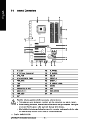
...) SPDIF_O 16) SPDIF_I 17) F_USB1/F_USB2 18) COMA 19) LPT 20) CLR_CMOS 21) CI Read the following guidelines before turning on the motherboard. Only for GA-P35C-DS3R. Unplug the power cord from the power outlet to prevent damage to the devices. • After installing the device and before connecting external devices... compliant with the connectors you wish to connect. • Before installing the devices, be sure to the connector on the computer, make sure your computer. GA-P35C-DS3R/DS3/S3 Motherboard - 22 -
...) SPDIF_O 16) SPDIF_I 17) F_USB1/F_USB2 18) COMA 19) LPT 20) CLR_CMOS 21) CI Read the following guidelines before turning on the motherboard. Only for GA-P35C-DS3R. Unplug the power cord from the power outlet to prevent damage to the devices. • After installing the device and before connecting external devices... compliant with the connectors you wish to connect. • Before installing the devices, be sure to the connector on the computer, make sure your computer. GA-P35C-DS3R/DS3/S3 Motherboard - 22 -
Manual
Page 24
... is recommended that a system fan be sure to prevent your CPU and system from overheating. Do not place a jumper cap on the connector. 34 33 GA-P35C-DS3R/DS3/S3 Motherboard - 24 - 2 1 The motherboard supports CPU fan speed control, which requires the use of floppy disk drives supported are not configuration jumper blocks. Definition...
... is recommended that a system fan be sure to prevent your CPU and system from overheating. Do not place a jumper cap on the connector. 34 33 GA-P35C-DS3R/DS3/S3 Motherboard - 24 - 2 1 The motherboard supports CPU fan speed control, which requires the use of floppy disk drives supported are not configuration jumper blocks. Definition...
Manual
Page 26
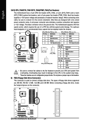
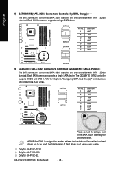
...GND Please connect the L-shaped end of hard drives must be an even number. Only for GA-P35C-S3. English 8) SATAII0/1/4/5 (SATA 3Gb/s Connectors, Controlled by GIGABYTE SATA2, Purple) The SATA connectors conform to be used, the total number of the SATA 3Gb.... If more than two hard drives are to SATA 3Gb/s standard and are compatible with SATA 1.5Gb/s standard. Each SATA connector supports a single SATA device. GA-P35C-DS3R/DS3/S3 Motherboard - 26 - Each SATA connector supports a single SATA device. SATAII0 7 1 1 7 SATAII1 SATAII4 7 1 Pin No. 1 2 3 4 5 6 7 ...
...GND Please connect the L-shaped end of hard drives must be an even number. Only for GA-P35C-S3. English 8) SATAII0/1/4/5 (SATA 3Gb/s Connectors, Controlled by GIGABYTE SATA2, Purple) The SATA connectors conform to be used, the total number of the SATA 3Gb.... If more than two hard drives are to SATA 3Gb/s standard and are compatible with SATA 1.5Gb/s standard. Each SATA connector supports a single SATA device. GA-P35C-DS3R/DS3/S3 Motherboard - 26 - Each SATA connector supports a single SATA device. SATAII0 7 1 1 7 SATAII1 SATAII4 7 1 Pin No. 1 2 3 4 5 6 7 ...
Manual
Page 27
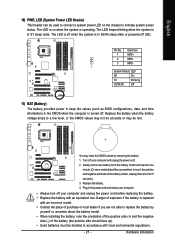
Hardware Installation The LED is off when the system is in S3/S4 sleep state or powered off your computer and unplug the power cord. 2. Danger of explosion if the battery is turned off your computer. • ... side should face up). • Used batteries must be handled in S1 sleep state. Definition 1 MPD+ 2 MPD- 3 MPD- 1 System Status LED S0 On S1 Blinking S3/S4/S5 Off 11) BAT (Battery) The battery provides power to keep the values (such as BIOS configurations, date, and time information) in the power...
Hardware Installation The LED is off when the system is in S3/S4 sleep state or powered off your computer and unplug the power cord. 2. Danger of explosion if the battery is turned off your computer. • ... side should face up). • Used batteries must be handled in S1 sleep state. Definition 1 MPD+ 2 MPD- 3 MPD- 1 System Status LED S0 On S1 Blinking S3/S4/S5 Off 11) BAT (Battery) The battery provides power to keep the values (such as BIOS configurations, date, and time information) in the power...
Manual
Page 28
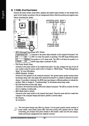
... a beep code. One single short beep will be heard if no problem is in S3/S4/S5 Off S3/S4 sleep state or powered off your chassis front panel module to this header according to this header, make sure the wire assignments and the pin assignments are matched correctly. GA-P35C-DS3R/DS3/S3 Motherboard - 28 -
... a beep code. One single short beep will be heard if no problem is in S3/S4/S5 Off S3/S4 sleep state or powered off your chassis front panel module to this header according to this header, make sure the wire assignments and the pin assignments are matched correctly. GA-P35C-DS3R/DS3/S3 Motherboard - 28 -
Manual
Page 30
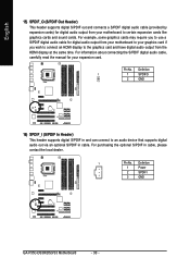
... if you wish to connect an HDMI display to certain expansion cards like graphics cards and sound cards. Pin No. Definition 1 Power 2 SPDIFI 3 GND GA-P35C-DS3R/DS3/S3 Motherboard - 30 - For example, some graphics cards may require you to an audio device that supports digital audio out via an optional S/PDIF in cable...
... if you wish to connect an HDMI display to certain expansion cards like graphics cards and sound cards. Pin No. Definition 1 Power 2 SPDIFI 3 GND GA-P35C-DS3R/DS3/S3 Motherboard - 30 - For example, some graphics cards may require you to an audio device that supports digital audio out via an optional S/PDIF in cable...

Manual
Page 32
... the CMOS values and before turning on the two pins to temporarily short the two pins or use a metal object like a screwdriver to factory defaults. GA-P35C-DS3R/DS3/S3 Motherboard - 32 - Failure to do so may cause damage to the motherboard. • After system restart, go to BIOS Setup to load factory defaults...
... the CMOS values and before turning on the two pins to temporarily short the two pins or use a metal object like a screwdriver to factory defaults. GA-P35C-DS3R/DS3/S3 Motherboard - 32 - Failure to do so may cause damage to the motherboard. • After system restart, go to BIOS Setup to load factory defaults...

