Manual
Page 4
... Contents ...6 OptionalItems ...6 GA-P35-DS3L/S3L Motherboard Layout 7 Block Diagram ...8 Chapter 1 Hardware Installation 9 1-1 Installation Precautions 9 1-2 Product Specifications 10 1-3 Installing the CPU and CPU Cooler 13 1-3-1 Installing the CPU 13 1-3-2 Installing the CPU Cooler 15 1-4 Installing the Memory 16 1-4-1 Dual Channel Memory Configuration 16 1-4-2 Installing a Memory 17 1-5 Installing an Expansion Card 18 1-6 Back Panel Connectors 19...
... Contents ...6 OptionalItems ...6 GA-P35-DS3L/S3L Motherboard Layout 7 Block Diagram ...8 Chapter 1 Hardware Installation 9 1-1 Installation Precautions 9 1-2 Product Specifications 10 1-3 Installing the CPU and CPU Cooler 13 1-3-1 Installing the CPU 13 1-3-2 Installing the CPU Cooler 15 1-4 Installing the Memory 16 1-4-1 Dual Channel Memory Configuration 16 1-4-2 Installing a Memory 17 1-5 Installing an Expansion Card 18 1-6 Back Panel Connectors 19...
Manual
Page 10
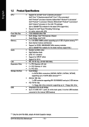
... 8 GB of system memory (Note 1) Š Dual channel memory architecture Š Support for DDR2 1066/800/667 MHz memory modules (Go to GIGABYTE's website for the latest memory support list.) Š Realtek ALC888 codec Š High Definition Audio Š 2/4/5.1/7.1-channel Š Support for S/PDIF ... supporting up to 1 floppy disk drive Š Integrated in the South Bridge Š Up to 12 USB 2.0/1.1 ports (6 on the back panel, 6 via the USB brackets connected to the internal USB headers) "*" Only the GA-P35-DS3L adopts All-Solid Capacitor design. GA-P35-DS3L/S3L Motherboard - 10 -
... 8 GB of system memory (Note 1) Š Dual channel memory architecture Š Support for DDR2 1066/800/667 MHz memory modules (Go to GIGABYTE's website for the latest memory support list.) Š Realtek ALC888 codec Š High Definition Audio Š 2/4/5.1/7.1-channel Š Support for S/PDIF ... supporting up to 1 floppy disk drive Š Integrated in the South Bridge Š Up to 12 USB 2.0/1.1 ports (6 on the back panel, 6 via the USB brackets connected to the internal USB headers) "*" Only the GA-P35-DS3L adopts All-Solid Capacitor design. GA-P35-DS3L/S3L Motherboard - 10 -
Manual
Page 18
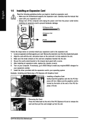
... card to prevent hardware damage. Locate an expansion slot that came with a screw. 5. Make sure the metal contacts on your expansion card(s). 7. GA-P35-DS3L/S3L Motherboard - 18 - Align the card with the expansion card in the slot. 3. After installing all expansion cards, replace the chassis cover(s). 6. ... Setup to correctly install your expansion card. • Always turn off the computer and unplug the power cord from the chassis back panel. 2. PCI Express x16 Slot PCI Express x1 Slot PCI Slot Follow the steps below to make any required BIOS changes for your computer...
... card to prevent hardware damage. Locate an expansion slot that came with a screw. 5. Make sure the metal contacts on your expansion card(s). 7. GA-P35-DS3L/S3L Motherboard - 18 - Align the card with the expansion card in the slot. 3. After installing all expansion cards, replace the chassis cover(s). 6. ... Setup to correctly install your expansion card. • Always turn off the computer and unplug the power cord from the chassis back panel. 2. PCI Express x16 Slot PCI Express x1 Slot PCI Slot Follow the steps below to make any required BIOS changes for your computer...
Manual
Page 26
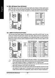
... 7 NC 8 No Pin 8 No Pin 9 LINE2_L 9 Line Out (L) 10 FSENSE2 10 NC • The front panel audio header supports HD audio by default. The LED is off (S5). GA-P35-DS3L/S3L Motherboard - 26 - The LED is on each wire instead of the motherboard header. Definition Pin No. Pin No. For... information about connecting the front panel audio module that has separated connectors on when the system...
... 7 NC 8 No Pin 8 No Pin 9 LINE2_L 9 Line Out (L) 10 FSENSE2 10 NC • The front panel audio header supports HD audio by default. The LED is off (S5). GA-P35-DS3L/S3L Motherboard - 26 - The LED is on each wire instead of the motherboard header. Definition Pin No. Pin No. For... information about connecting the front panel audio module that has separated connectors on when the system...

Manual
Page 70
... 8CH Speaker according to the type of device you connect. Doubleclick the icon to set up. Step 3: Everytime you wish to access the Audio Control Panel. GA-P35-DS3L/S3L Motherboard - 70 - Step 2: Click the Audio I/O tab. Then click OK to an audio jack, the Connected device box appears. Select the device according to the...
... 8CH Speaker according to the type of device you connect. Doubleclick the icon to set up. Step 3: Everytime you wish to access the Audio Control Panel. GA-P35-DS3L/S3L Motherboard - 70 - Step 2: Click the Audio I/O tab. Then click OK to an audio jack, the Connected device box appears. Select the device according to the...
Manual
Page 72
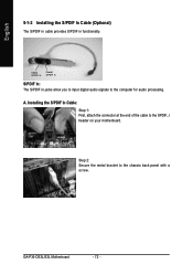
Installing the S/PDIF In Cable: Step 1: First, attach the connector at the end of the cable to the computer for audio processing. English 5-1-2 Installing the S/PDIF In Cable (Optional) The S/PDIF in cable provides S/PDIF in jacks allow you to input digital audio signals to the SPDIF_I header on your motherboard. Optical S/PDIF In Coaxial S/PDIF In S/PDIF In: The S/PDIF in functionality. A. Step 2: Secure the metal bracket to the chassis back panel with a screw. GA-P35-DS3L/S3L Motherboard - 72 -
Installing the S/PDIF In Cable: Step 1: First, attach the connector at the end of the cable to the computer for audio processing. English 5-1-2 Installing the S/PDIF In Cable (Optional) The S/PDIF in cable provides S/PDIF in jacks allow you to input digital audio signals to the SPDIF_I header on your motherboard. Optical S/PDIF In Coaxial S/PDIF In S/PDIF In: The S/PDIF in functionality. A. Step 2: Secure the metal bracket to the chassis back panel with a screw. GA-P35-DS3L/S3L Motherboard - 72 -
Manual
Page 74
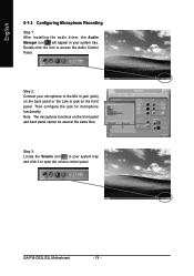
...will appear in your system tray and click it to access the Audio Control Panel. Note: The microphone functions on the front panel. Double-click the icon to open the volume control panel GA-P35-DS3L/S3L Motherboard - 74 - Then configure the jack for microphone functionality. Step 2: Connect... your microphone to the Mic in jack (pink) on the back panel or the Line in your ...
...will appear in your system tray and click it to access the Audio Control Panel. Note: The microphone functions on the front panel. Double-click the icon to open the volume control panel GA-P35-DS3L/S3L Motherboard - 74 - Then configure the jack for microphone functionality. Step 2: Connect... your microphone to the Mic in jack (pink) on the back panel or the Line in your ...


