Manual
Page 4
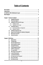
... ...6 GA-N650SLI-DS4L Motherboard Layout 7 Block Diagram ...8 Chapter 1 Hardware Installation 9 1-1 Installation Precautions 9 1-2 Product Specifications 10 1-3 Installing the CPU and CPU Cooler 13 1-3-1 Installing the CPU 13 1-3-2 Installing the CPU Cooler 15 1-4 Installing the Memory 16 1-4-1 Dual Channel Memory Configuration 16 1-4-2 Installing a Memory 17 1-5 Installing an Expansion Card 18 1-6 Setup of an SLI (Scalable Link Interface) Configuration 19 1-7 Back Panel Connectors 22 1-8 Internal Connectors 24 Chapter 2 BIOS Setup 35 2-1 Startup Screen 36 2-2 The Main Menu 37...
... ...6 GA-N650SLI-DS4L Motherboard Layout 7 Block Diagram ...8 Chapter 1 Hardware Installation 9 1-1 Installation Precautions 9 1-2 Product Specifications 10 1-3 Installing the CPU and CPU Cooler 13 1-3-1 Installing the CPU 13 1-3-2 Installing the CPU Cooler 15 1-4 Installing the Memory 16 1-4-1 Dual Channel Memory Configuration 16 1-4-2 Installing a Memory 17 1-5 Installing an Expansion Card 18 1-6 Setup of an SLI (Scalable Link Interface) Configuration 19 1-7 Back Panel Connectors 22 1-8 Internal Connectors 24 Chapter 2 BIOS Setup 35 2-1 Startup Screen 36 2-2 The Main Menu 37...

Manual
Page 5
... Utilities 68 4-2-1 Updating the BIOS with the Q-Flash Utility 68 4-2-2 Updating the BIOS with the @BIOS Utility 71 4-3 EasyTune 5 ...73 4-4 Windows Vista ReadyBoost 74 Chapter 5 Appendix ...75 5-1 Configuring SATA Hard Drive(s 75 5-1-1 Configuring the Onboard SATA Controller 75 5-1-2 Making a SATA RAID Driver Diskette 80 5-1-3 Installing the SATA RAID Driver and Operating System 81 5-2 ConfiguringAudio Input and Output 84 5-2-1 Configuring 2/4/5.1/7.1-Channel Audio 84 5-2-2 Installing the S/PDIF In Cable (Optional 86 5-2-3 Configuring Microphone Recording 88 5-2-4 Using the Sound...
... Utilities 68 4-2-1 Updating the BIOS with the Q-Flash Utility 68 4-2-2 Updating the BIOS with the @BIOS Utility 71 4-3 EasyTune 5 ...73 4-4 Windows Vista ReadyBoost 74 Chapter 5 Appendix ...75 5-1 Configuring SATA Hard Drive(s 75 5-1-1 Configuring the Onboard SATA Controller 75 5-1-2 Making a SATA RAID Driver Diskette 80 5-1-3 Installing the SATA RAID Driver and Operating System 81 5-2 ConfiguringAudio Input and Output 84 5-2-1 Configuring 2/4/5.1/7.1-Channel Audio 84 5-2-2 Installing the S/PDIF In Cable (Optional 86 5-2-3 Configuring Microphone Recording 88 5-2-4 Using the Sound...
Manual
Page 10
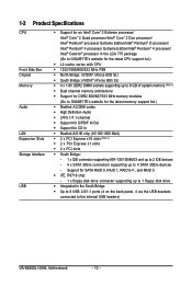
... memory support list.) Š Realtek ALC888 codec Š High Definition Audio Š 2/4/5.1/7.1-channel Š Support for S/PDIF In/Out Š Support for SATA RAID 0, RAID 1, RAID 0+1, and RAID 5 Š iTE IT8718 chip: - 1 x floppy disk drive connector supporting up to the internal USB headers) GA-N650SLI-DS4L Motherboard - 10 - Support for CD In Š Realtek 8211B chip (10/100/1000 Mbit) Š 2 x PCI Express x16 slots (Note 2) Š 2 x PCI Express x1 slots Š 2 x PCI slots Š South Bridge: - 1 x IDE connector supporting ATA-133/100/66/33 and up to 2 IDE devices...
... memory support list.) Š Realtek ALC888 codec Š High Definition Audio Š 2/4/5.1/7.1-channel Š Support for S/PDIF In/Out Š Support for SATA RAID 0, RAID 1, RAID 0+1, and RAID 5 Š iTE IT8718 chip: - 1 x floppy disk drive connector supporting up to the internal USB headers) GA-N650SLI-DS4L Motherboard - 10 - Support for CD In Š Realtek 8211B chip (10/100/1000 Mbit) Š 2 x PCI Express x16 slots (Note 2) Š 2 x PCI Express x1 slots Š 2 x PCI slots Š South Bridge: - 1 x IDE connector supporting ATA-133/100/66/33 and up to 2 IDE devices...
Manual
Page 16
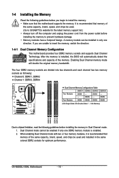
... memory support list.) • Always turn off the computer and unplug the power cord from the power outlet before installing the memory in Dual Channel mode. 1. Enabling Dual Channel memory mode will automatically detect the specifications and capacity of the same capacity, brand, speed, and chips be used and installed in the same colored DDR2 sockets for optimum performance. It is installed. 2. After the memory is recommended that the motherboard supports the memory. DS/SS - - GA-N650SLI-DS4L Motherboard - 16 - 1-4 Installing the Memory...
... memory support list.) • Always turn off the computer and unplug the power cord from the power outlet before installing the memory in Dual Channel mode. 1. Enabling Dual Channel memory mode will automatically detect the specifications and capacity of the same capacity, brand, speed, and chips be used and installed in the same colored DDR2 sockets for optimum performance. It is installed. 2. After the memory is recommended that the motherboard supports the memory. DS/SS - - GA-N650SLI-DS4L Motherboard - 16 - 1-4 Installing the Memory...
Manual
Page 18
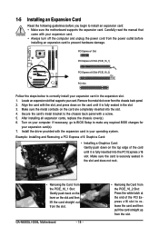
... slot. 4. After installing all expansion cards, replace the chassis cover(s). 6. Turn on the slot and then lift the card straight out from the slot. PCI Express x1 Slot PCI Express x16 Slot (PCIE_16_1) PCI Express x16 Slot (PCIE_16_2) PCI Slot Follow the steps below to release the card and then pull the card straight up from the slot. If necessary, go to BIOS Setup to make any required BIOS changes for your operating system. Carefully read the manual...
... slot. 4. After installing all expansion cards, replace the chassis cover(s). 6. Turn on the slot and then lift the card straight out from the slot. PCI Express x1 Slot PCI Express x16 Slot (PCIE_16_1) PCI Express x16 Slot (PCIE_16_2) PCI Slot Follow the steps below to release the card and then pull the card straight up from the slot. If necessary, go to BIOS Setup to make any required BIOS changes for your operating system. Carefully read the manual...
Manual
Page 19
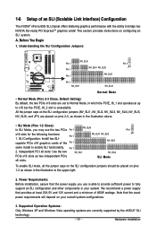
... model to the upper-right. 2. SLI Mode Pin 1 JP1 To enable SLI mode, all the jumper caps on the SLI configuration jumpers should be placed on pins 2-3, as shown in your overall system configurations. 3. Understanding the SLI Configuration Jumpers: NV_SLI6 Pin 1 Pin 1 NV_SLI4 NV_SLI5 Pin 1 NV_SLI3 Pin 1 JP1 Pin 1 NV_SLI1 NV_SLI2 Normal Mode • Normal Mode (Pins 2-3 Close, Default Setting): By default, the two PCIe x16 slots are currently supported by the nVIDIA® SLI technology. - 19 - Supported Operation Systems: Only Windows XP and Windows...
... model to the upper-right. 2. SLI Mode Pin 1 JP1 To enable SLI mode, all the jumper caps on the SLI configuration jumpers should be placed on pins 2-3, as shown in your overall system configurations. 3. Understanding the SLI Configuration Jumpers: NV_SLI6 Pin 1 Pin 1 NV_SLI4 NV_SLI5 Pin 1 NV_SLI3 Pin 1 JP1 Pin 1 NV_SLI1 NV_SLI2 Normal Mode • Normal Mode (Pins 2-3 Close, Default Setting): By default, the two PCIe x16 slots are currently supported by the nVIDIA® SLI technology. - 19 - Supported Operation Systems: Only Windows XP and Windows...
Manual
Page 21
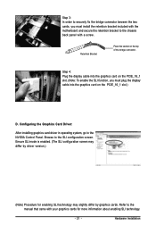
... Graphics Card Driver: After installing graphics card driver in operating system, go to the SLI configuration screen. Ensure SLI mode is enabled. (The SLI configuration screen may slightly differ by driver version.) (Note) Procedure for more information about enabling SLI technology. - 21 - Hardware Installation Browse to the NVIDIA Control Panel. Refer to the manual that came with a screw. Retention Bracket Place this section on the PCIE_16_1 slot. (Note: To enable the SLI function, you must plug the display cable into the graphics card...
... Graphics Card Driver: After installing graphics card driver in operating system, go to the SLI configuration screen. Ensure SLI mode is enabled. (The SLI configuration screen may slightly differ by driver version.) (Note) Procedure for more information about enabling SLI technology. - 21 - Hardware Installation Browse to the NVIDIA Control Panel. Refer to the manual that came with a screw. Retention Bracket Place this section on the PCIE_16_1 slot. (Note: To enable the SLI function, you must plug the display cable into the graphics card...
Manual
Page 26
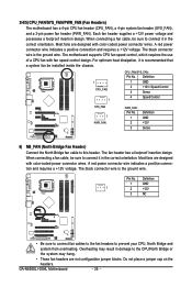
... voltage. The black connector wire is the ground wire. Pin No. GA-N650SLI-DS4L Motherboard - 26 - For optimum heat dissipation, it is recommended that a system fan be sure to the CPU/North Bridge or the system may hang. • These fan headers are designed with color-coded power connector wires. Most fans are not configuration jumper blocks. The black connector wire is the ground wire. Do not place a jumper cap on the headers. When connecting a fan cable, be installed...
... voltage. The black connector wire is the ground wire. Pin No. GA-N650SLI-DS4L Motherboard - 26 - For optimum heat dissipation, it is recommended that a system fan be sure to the CPU/North Bridge or the system may hang. • These fan headers are designed with color-coded power connector wires. Most fans are not configuration jumper blocks. The black connector wire is the ground wire. Do not place a jumper cap on the headers. When connecting a fan cable, be installed...
Manual
Page 30
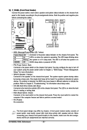
... Panel Header) Connect the power switch, reset switch, speaker and system status indicator on the chassis front panel to this header, make sure the wire assignments and the pin assignments are matched correctly. Note the positive and negative pins before connecting the cables. A front panel module mainly consists of power switch, reset switch, power LED, hard drive activity LED, speaker and etc. The LED keeps blinking when S1 Blinking the system is detected, the BIOS may configure the way to turn off...
... Panel Header) Connect the power switch, reset switch, speaker and system status indicator on the chassis front panel to this header, make sure the wire assignments and the pin assignments are matched correctly. Note the positive and negative pins before connecting the cables. A front panel module mainly consists of power switch, reset switch, power LED, hard drive activity LED, speaker and etc. The LED keeps blinking when S1 Blinking the system is detected, the BIOS may configure the way to turn off...
Manual
Page 41
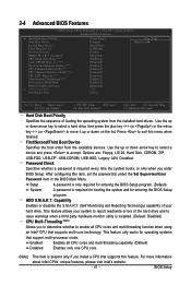
...hardware monitor utility is required for booting the system and for operating systems that supports multi-core technology. HDD S.M.A.R.T. Setup A password is only required for entering the BIOS Setup program. (Default) System A password is installed. (Default: Disabled) CPU Multi-Threading (Note) Allows you enter BIOS Setup. Capability CPU Multi-Threading (Note) Limit CPUID Max. 2-4 Advanced BIOS Features CMOS Setup Utility-Copyright (C) 1984-2007 Award Software Advanced BIOS Features ` Hard Disk Boot Priority First Boot Device Second Boot Device Third Boot Device Password...
...hardware monitor utility is required for booting the system and for operating systems that supports multi-core technology. HDD S.M.A.R.T. Setup A password is only required for entering the BIOS Setup program. (Default) System A password is installed. (Default: Disabled) CPU Multi-Threading (Note) Allows you enter BIOS Setup. Capability CPU Multi-Threading (Note) Limit CPUID Max. 2-4 Advanced BIOS Features CMOS Setup Utility-Copyright (C) 1984-2007 Award Software Advanced BIOS Features ` Hard Disk Boot Priority First Boot Device Second Boot Device Third Boot Device Password...
Manual
Page 42
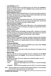
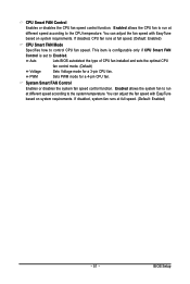
... enabled, the CPU core frequency and voltage will allow a platform to Enabled for the graphics chip and is configurable only if the Robust Graphics Booster option is set this feature. PCI Slot Sets the PCI graphics card as the first display. (Note) This item is overheated. (Default: Enabled) CPU EIST Function (Note) Enables or disables Enhanced Intel SpeedStep Technology (EIST). GA-N650SLI-DS4L Motherboard - 42 - Set this item to viruses and malicious buffer overflow attacks when working with its supporting software and system. (Default: Enabled) CPU...
... enabled, the CPU core frequency and voltage will allow a platform to Enabled for the graphics chip and is configurable only if the Robust Graphics Booster option is set this feature. PCI Slot Sets the PCI graphics card as the first display. (Note) This item is overheated. (Default: Enabled) CPU EIST Function (Note) Enables or disables Enhanced Intel SpeedStep Technology (EIST). GA-N650SLI-DS4L Motherboard - 42 - Set this item to viruses and malicious buffer overflow attacks when working with its supporting software and system. (Default: Enabled) CPU...
Manual
Page 44
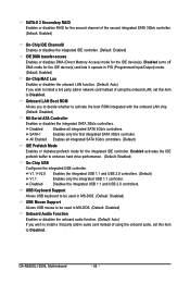
... audio card instead of using the onboard LAN, set this item to Disabled. SATA-II 2 Secondary RAID Enables or disables RAID for the second channel of the second integrated SATA 3Gb/s controller. (Default: Enabled) On-Chip IDE Channel0 Enables or disables the integrated IDE controller. (Default: Enabled) IDE DMA transfer access Enables or disables DMA (Direct Memory Access) mode for the integrated IDE controller. Disabled Disables all integrated SATA 3Gb/s controllers. (Default) IDE Prefetch Mode Enables or disbales prefetch mode for the IDE device(s). GA-N650SLI-DS4L Motherboard...
... audio card instead of using the onboard LAN, set this item to Disabled. SATA-II 2 Secondary RAID Enables or disables RAID for the second channel of the second integrated SATA 3Gb/s controller. (Default: Enabled) On-Chip IDE Channel0 Enables or disables the integrated IDE controller. (Default: Enabled) IDE DMA transfer access Enables or disables DMA (Direct Memory Access) mode for the integrated IDE controller. Disabled Disables all integrated SATA 3Gb/s controllers. (Default) IDE Prefetch Mode Enables or disbales prefetch mode for the IDE device(s). GA-N650SLI-DS4L Motherboard...
Manual
Page 46
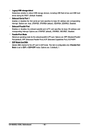
..., Disabled. GA-N650SLI-DS4L Motherboard - 46 - Parallel Port Mode Selects an operating mode for the LPT port in ECP mode. ECP Mode Use DMA Selects DMA channel for the onboard parallel (LPT) port. Options are : SPP (Standard Parallel Port)(default), EPP (Enhanced Parallel Port), ECP (Extended Capabilities Port), ECP+EPP. Options are : 378/IRQ7 (default), 278/IRQ5, 3BC/IRQ7, Disabled. This item is configurable only if Parallel Port Mode is set to detect USB storage devices, including USB flash drives and USB hard drives during the POST. (Default: Enabled) Onboard Serial Port...
..., Disabled. GA-N650SLI-DS4L Motherboard - 46 - Parallel Port Mode Selects an operating mode for the LPT port in ECP mode. ECP Mode Use DMA Selects DMA channel for the onboard parallel (LPT) port. Options are : SPP (Standard Parallel Port)(default), EPP (Enhanced Parallel Port), ECP (Extended Capabilities Port), ECP+EPP. Options are : 378/IRQ7 (default), 278/IRQ5, 3BC/IRQ7, Disabled. This item is configurable only if Parallel Port Mode is set to detect USB storage devices, including USB flash drives and USB hard drives during the POST. (Default: Enabled) Onboard Serial Port...
Manual
Page 47
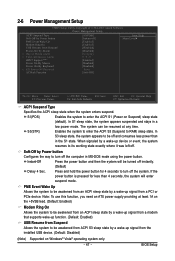
... enter the ACPI S1 (Power on Windows® Vista® operating system only. - 47 - Soft-Off by Power button Configures the way to be turned off and consumes less power than 4 seconds, the system will be awakened from an ACPI sleep state by a wake-up signal from a PCI or PCIe device. PME Event Wake Up Allows the system to turn off . 2-6 Power Management Setup CMOS Setup Utility-Copyright (C) 1984-2007 Award Software Power Management Setup ACPI Suspend Type...
... enter the ACPI S1 (Power on Windows® Vista® operating system only. - 47 - Soft-Off by Power button Configures the way to be turned off and consumes less power than 4 seconds, the system will be awakened from an ACPI sleep state by a wake-up signal from a PCI or PCIe device. PME Event Wake Up Allows the system to turn off . 2-6 Power Management Setup CMOS Setup Utility-Copyright (C) 1984-2007 Award Software Power Management Setup ACPI Suspend Type...
Manual
Page 51
... system fan runs at different speed according to the system temperature. You can adjust the fan speed with EasyTune based on system requirements. Auto Lets BIOS autodetect the type of CPU fan installed and sets the optimal CPU fan control mode. (Default) Voltage Sets Voltage mode for a 4-pin CPU fan. BIOS Setup Enabled allows the CPU fan to run at full speed. (Default: Enabled) CPU Smart FAN Mode Specifies how to Enabled. Enabled allows the system fan to run at full speed. (Default: Enabled) - 51 - CPU Smart FAN Control Enables or disables the CPU fan speed control...
... system fan runs at different speed according to the system temperature. You can adjust the fan speed with EasyTune based on system requirements. Auto Lets BIOS autodetect the type of CPU fan installed and sets the optimal CPU fan control mode. (Default) Voltage Sets Voltage mode for a 4-pin CPU fan. BIOS Setup Enabled allows the CPU fan to run at full speed. (Default: Enabled) CPU Smart FAN Mode Specifies how to Enabled. Enabled allows the system fan to run at full speed. (Default: Enabled) - 51 - CPU Smart FAN Control Enables or disables the CPU fan speed control...
Manual
Page 57
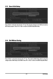
... the key. 2-13 Save & Exit Setup CMOS Setup Utility-Copyright (C) 1984-2007 Award Software ` Standard CMOS Features Load Fail-Safe Defaults ` Advanced BIOS Features Load Optimized Defaults ` Integrated Peripherals Set Supervisor Password ` Power Management Setup Save to CMOS and EXIT (SYe/tNU)?seYr Password ` PnP/PCI Configurations Save & Exit Setup ` PC Health Status Exit Without Saving ` MB Intelligent Tweaker(M.I .T.) ESC: Quit F8: Q-Flash KLJI: Select Item F10: Save & Exit Setup F11: Save CMOS to the BIOS Setup Main Menu. - 57...
... the key. 2-13 Save & Exit Setup CMOS Setup Utility-Copyright (C) 1984-2007 Award Software ` Standard CMOS Features Load Fail-Safe Defaults ` Advanced BIOS Features Load Optimized Defaults ` Integrated Peripherals Set Supervisor Password ` Power Management Setup Save to CMOS and EXIT (SYe/tNU)?seYr Password ` PnP/PCI Configurations Save & Exit Setup ` PC Health Status Exit Without Saving ` MB Intelligent Tweaker(M.I .T.) ESC: Quit F8: Q-Flash KLJI: Select Item F10: Save & Exit Setup F11: Save CMOS to the BIOS Setup Main Menu. - 57...
Manual
Page 75
... SATA RAID driver and operating system. (Note 2) Before you use two hard drives with identical model and capacity). Then connect the power connector from your computer. Install SATA hard drive(s) in your computer Attach one hard drive. • An empty formatted floppy disk. • Windows Vista/XP/2000 setup disk. • Motherboard driver disk. 5-1-1 Configuring the Onboard SATA Controller A. Configure a RAID array in BIOS Setup. Appendix If you do not want to create RAID, you may prepare only one end of the SATA signal cable...
... SATA RAID driver and operating system. (Note 2) Before you use two hard drives with identical model and capacity). Then connect the power connector from your computer. Install SATA hard drive(s) in your computer Attach one hard drive. • An empty formatted floppy disk. • Windows Vista/XP/2000 setup disk. • Motherboard driver disk. 5-1-1 Configuring the Onboard SATA Controller A. Configure a RAID array in BIOS Setup. Appendix If you do not want to create RAID, you may prepare only one end of the SATA signal cable...
Manual
Page 76
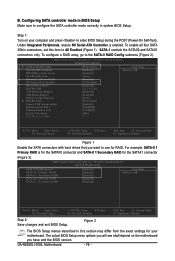
... and the BIOS version. CMOS Setup Utility-Copyright (C) 1984-2007 Award Software Integrated Peripherals ` SATA-II RAID Config On-Chip IDE Channel0 IDE DMA transfer access On-Chip MAC Lan Onboard LAN Boot ROM NV Serial-ATA Controller IDE Prefetch Mode On-Chip USB USB Keyboard Support USB Mouse Support Onboard Audio Function ` SMART LAN Legacy USB storage detect Onboard Serial Port 1 Onboard Parallel Port Parallel Port Mode x ECP Mode Use DMA [Press Enter] [Enabled] [Enabled] [Auto] [Disabled] [All Enabled] [Enabled] [V1.1+V2.0] [Disabled] [Disabled] [Auto] [Press Enter] [Enabled] [3F8/IRQ4...
... and the BIOS version. CMOS Setup Utility-Copyright (C) 1984-2007 Award Software Integrated Peripherals ` SATA-II RAID Config On-Chip IDE Channel0 IDE DMA transfer access On-Chip MAC Lan Onboard LAN Boot ROM NV Serial-ATA Controller IDE Prefetch Mode On-Chip USB USB Keyboard Support USB Mouse Support Onboard Audio Function ` SMART LAN Legacy USB storage detect Onboard Serial Port 1 Onboard Parallel Port Parallel Port Mode x ECP Mode Use DMA [Press Enter] [Enabled] [Enabled] [Auto] [Disabled] [All Enabled] [Enabled] [V1.1+V2.0] [Disabled] [Disabled] [Auto] [Press Enter] [Enabled] [3F8/IRQ4...
Manual
Page 80
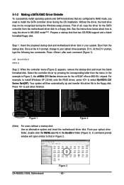
... this driver file to copy the driver in Figure 2, the nVIDIA C51 Series drivers are configured to RAID mode, you need to install the SATA controller driver during the Windows setup process. See the instructions below about how to the floppy disk. Figure 1 Figure 2 (Note) For users without a startup disk: Use an alternative system and insert the motherboard driver disk. Prepare a startup disk that has CD-ROM support and a blank formatted floppy disk. GA-N650SLI-DS4L Motherboard Figure 3 - 80 - Without the driver, the hard drive...
... this driver file to copy the driver in Figure 2, the nVIDIA C51 Series drivers are configured to RAID mode, you need to install the SATA controller driver during the Windows setup process. See the instructions below about how to the floppy disk. Figure 1 Figure 2 (Note) For users without a startup disk: Use an alternative system and insert the motherboard driver disk. Prepare a startup disk that has CD-ROM support and a blank formatted floppy disk. GA-N650SLI-DS4L Motherboard Figure 3 - 80 - Without the driver, the hard drive...
Manual
Page 81
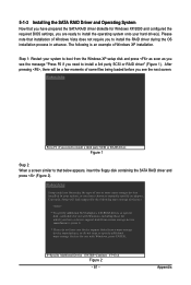
..., CD-ROM drives, or special disk controllers for use with Windows, press ENTER. After pressing , there will load support for the following is an example of some files being loaded before you see the message "Press F6 if you need to install a third party SCSI or RAID driver. Windows Setup Setup could not determine the type of Windows Vista does not require you to install the RAID driver during the OS installation process...
..., CD-ROM drives, or special disk controllers for use with Windows, press ENTER. After pressing , there will load support for the following is an example of some files being loaded before you see the message "Press F6 if you need to install a third party SCSI or RAID driver. Windows Setup Setup could not determine the type of Windows Vista does not require you to install the RAID driver during the OS installation process...


