Manual
Page 4
... ...6 OptionalItems ...6 GA-N650SLI-DS4L Motherboard Layout 7 Block Diagram ...8 Chapter 1 Hardware Installation 9 1-1 Installation Precautions 9 1-2 Product Specifications 10 1-3 Installing the CPU and CPU Cooler 13 1-3-1 Installing the CPU 13 1-3-2 Installing the CPU Cooler 15 1-4 Installing the Memory 16 1-4-1 Dual Channel Memory Configuration 16 1-4-2 Installing a Memory 17 1-5 Installing an Expansion Card 18 1-6 Setup of an SLI (Scalable...
... ...6 OptionalItems ...6 GA-N650SLI-DS4L Motherboard Layout 7 Block Diagram ...8 Chapter 1 Hardware Installation 9 1-1 Installation Precautions 9 1-2 Product Specifications 10 1-3 Installing the CPU and CPU Cooler 13 1-3-1 Installing the CPU 13 1-3-2 Installing the CPU Cooler 15 1-4 Installing the Memory 16 1-4-1 Dual Channel Memory Configuration 16 1-4-2 Installing a Memory 17 1-5 Installing an Expansion Card 18 1-6 Setup of an SLI (Scalable...
Manual
Page 6
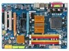
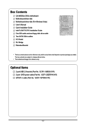
...12CF1-2SERPW-01R) S/PDIF in cable (Part No. 12CR1-1SPDIN-01R) - 6 - The box contents are for reference only. Box Contents GA-N650SLI-DS4L motherboard Motherboard driver disk Motherboard driver disk (For Windows Vista) User's Manual Quick Installation Guide Intel® LGA775 CPU Installation Guide One IDE ...cable and one floppy disk drive cable Two SATA 3Gb/s cables I/O Shield SLI Bridge Retention Bracket • The box contents above are subject to change without notice. • The motherboard image is for reference ...
...12CF1-2SERPW-01R) S/PDIF in cable (Part No. 12CR1-1SPDIN-01R) - 6 - The box contents are for reference only. Box Contents GA-N650SLI-DS4L motherboard Motherboard driver disk Motherboard driver disk (For Windows Vista) User's Manual Quick Installation Guide Intel® LGA775 CPU Installation Guide One IDE ...cable and one floppy disk drive cable Two SATA 3Gb/s cables I/O Shield SLI Bridge Retention Bracket • The box contents above are subject to change without notice. • The motherboard image is for reference ...
Manual
Page 8
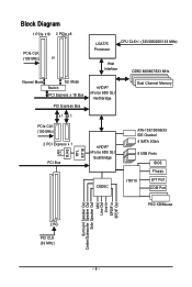
...) or LGA775 Processor CPU CLK+/- (333/266/200/133 MHz) Host Interface DDR2 800/667/533 MHz Normal Mode SLI Mode Switch PCI Express x 16 Bus PCI Express Bus nVIDIA® nForce 650i SLI Northbridge Dual Channel Memory x1 x1 PCIe CLK (100 MHz) 2 PCI Express x 1 PCI Bus LAN RJ45 RTL 8211B... nVIDIA® nForce 650i SLI Southbridge CODEC ATA-133/100/66/33 IDE Channel 4 SATA 3Gb/s 8 USB Ports BIOS Floppy IT8718 LPT Port COM Port PS/2 KB/Mouse 2 PCI PCI ...
...) or LGA775 Processor CPU CLK+/- (333/266/200/133 MHz) Host Interface DDR2 800/667/533 MHz Normal Mode SLI Mode Switch PCI Express x 16 Bus PCI Express Bus nVIDIA® nForce 650i SLI Northbridge Dual Channel Memory x1 x1 PCIe CLK (100 MHz) 2 PCI Express x 1 PCI Bus LAN RJ45 RTL 8211B... nVIDIA® nForce 650i SLI Southbridge CODEC ATA-133/100/66/33 IDE Channel 4 SATA 3Gb/s 8 USB Ports BIOS Floppy IT8718 LPT Port COM Port PS/2 KB/Mouse 2 PCI PCI ...
Manual
Page 10
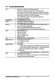
... up to the internal USB headers) GA-N650SLI-DS4L Motherboard - 10 - Support for SATA RAID 0, RAID 1, RAID 0+1, and RAID 5 Š iTE IT8718 chip: - 1 x floppy disk drive connector supporting up to 1 floppy disk drive Š Integrated in the LGA 775 package (Go to GIGABYTE's website for the latest CPU support list....) Š L2 cache varies with CPU Š 1333/1066/800/533 MHz FSB Š North Bridge: nVIDIA® nForce 650i SLI Š South Bridge: nVIDIA® nForce 650i SLI Š 4 x 1.8V DDR2 DIMM ...
... up to the internal USB headers) GA-N650SLI-DS4L Motherboard - 10 - Support for SATA RAID 0, RAID 1, RAID 0+1, and RAID 5 Š iTE IT8718 chip: - 1 x floppy disk drive connector supporting up to 1 floppy disk drive Š Integrated in the LGA 775 package (Go to GIGABYTE's website for the latest CPU support list....) Š L2 cache varies with CPU Š 1333/1066/800/533 MHz FSB Š North Bridge: nVIDIA® nForce 650i SLI Š South Bridge: nVIDIA® nForce 650i SLI Š 4 x 1.8V DDR2 DIMM ...
Manual
Page 12
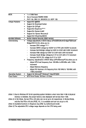
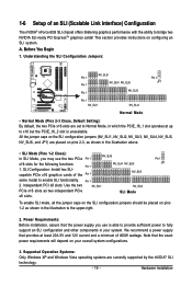
... (Note 4) - Increase South Bridge voltage by 0.05V to 0.35V with 0.1V increment - Increase FSB voltage by 0.1V to 0.3V with 0.05V increment - Adjust Memory frequency - GA-N650SLI-DS4L Motherboard - 12 - Increase VCC12_DL voltage by 0.025V to 0.775V with 0.05V increment - Adjust PCI Express x16 frequency from 100 MHz to 650 MHz with 1 MHz... increment - In Normal Mode, only the first PCIe x16 slot (PCIE_16_1) is installed, the actual memory size displayed will be less than 4 GB. (Note 2) In SLI Mode, the two PCIe x16 slots can run at up to x8 respectively.
... (Note 4) - Increase South Bridge voltage by 0.05V to 0.35V with 0.1V increment - Increase FSB voltage by 0.1V to 0.3V with 0.05V increment - Adjust Memory frequency - GA-N650SLI-DS4L Motherboard - 12 - Increase VCC12_DL voltage by 0.025V to 0.775V with 0.05V increment - Adjust PCI Express x16 frequency from 100 MHz to 650 MHz with 1 MHz... increment - In Normal Mode, only the first PCIe x16 slot (PCIE_16_1) is installed, the actual memory size displayed will be less than 4 GB. (Note 2) In SLI Mode, the two PCIe x16 slots can run at up to x8 respectively.
Manual
Page 19
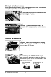
... a power supply that the exact power requirements will depend on pins 2-3, as two independent PCIe x8 slots. Hardware Installation SLI Configuration: Install two SLI- Pin 1 2. Power Requirements: Before installation, assure that the power supply you may use is unavailable. This section provides...least 20A 5V and 12V current and a minimum of 400W wattage. Note that provides at up to the upper-right. 2. Understanding the SLI Configuration Jumpers: NV_SLI6 Pin 1 Pin 1 NV_SLI4 NV_SLI5 Pin 1 NV_SLI3 Pin 1 JP1 Pin 1 NV_SLI1 NV_SLI2 Normal Mode • Normal ...
... a power supply that the exact power requirements will depend on pins 2-3, as two independent PCIe x8 slots. Hardware Installation SLI Configuration: Install two SLI- Pin 1 2. Power Requirements: Before installation, assure that the power supply you may use is unavailable. This section provides...least 20A 5V and 12V current and a minimum of 400W wattage. Note that provides at up to the upper-right. 2. Understanding the SLI Configuration Jumpers: NV_SLI6 Pin 1 Pin 1 NV_SLI4 NV_SLI5 Pin 1 NV_SLI3 Pin 1 JP1 Pin 1 NV_SLI1 NV_SLI2 Normal Mode • Normal ...
Manual
Page 20
... (the GC-DGBR2-RH) in the SLI gold edge connectors on top of the graphics card GA-N650SLI-DS4L Motherboard - 20 - Female slots on the bridge connector Gold edge connector on the PCIE_16_1 and PCIE_16_2 slots. B. Connecting Two Graphics Cards: Step 1: Observe the steps in the photo to SLI Mode. Make sure the two mini...
... (the GC-DGBR2-RH) in the SLI gold edge connectors on top of the graphics card GA-N650SLI-DS4L Motherboard - 20 - Female slots on the bridge connector Gold edge connector on the PCIE_16_1 and PCIE_16_2 slots. B. Connecting Two Graphics Cards: Step 1: Observe the steps in the photo to SLI Mode. Make sure the two mini...
Manual
Page 21
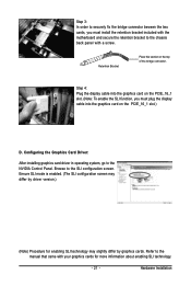
... card on the top of the bridge connector. Configuring the Graphics Card Driver: After installing graphics card driver in operating system, go to the SLI configuration screen. Browse to the NVIDIA Control Panel. Step 3: In order to securely fix the bridge connector beween the two cards, you must... plug the display cable into the graphics card on the PCIE_16_1 slot. (Note: To enable the SLI function, you must install the retention bracket included with the motherboard and secure the retention bracket to the chassis back panel with your graphics ...
... card on the top of the bridge connector. Configuring the Graphics Card Driver: After installing graphics card driver in operating system, go to the SLI configuration screen. Browse to the NVIDIA Control Panel. Step 3: In order to securely fix the bridge connector beween the two cards, you must... plug the display cable into the graphics card on the PCIE_16_1 slot. (Note: To enable the SLI function, you must install the retention bracket included with the motherboard and secure the retention bracket to the chassis back panel with your graphics ...
Manual
Page 28
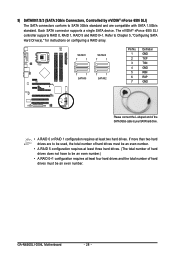
Each SATA connector supports a single SATA device. GA-N650SLI-DS4L Motherboard - 28 - Refer to Chapter 5, "Configuring SATA Hard Drive(s)," for instructions on configuring a RAID array. If more than two hard drives are compatible with SATA 1.... and the total number of hard drives does not have to be an even number. 9) SATAII0/1/2/3 (SATA 3Gb/s Connectors, Controlled by nVIDIA® nForce 650i SLI) The SATA connectors conform to SATA 3Gb/s standard and are to be used, the total number of hard drives must be an even number. •...
Each SATA connector supports a single SATA device. GA-N650SLI-DS4L Motherboard - 28 - Refer to Chapter 5, "Configuring SATA Hard Drive(s)," for instructions on configuring a RAID array. If more than two hard drives are compatible with SATA 1.... and the total number of hard drives does not have to be an even number. 9) SATAII0/1/2/3 (SATA 3Gb/s Connectors, Controlled by nVIDIA® nForce 650i SLI) The SATA connectors conform to SATA 3Gb/s standard and are to be used, the total number of hard drives must be an even number. •...
Manual
Page 80
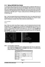
... For example, to install Windows XP (32-bit) onto the RAID drives, press to exit when finished. From your optical drive (example: D:\>). GA-N650SLI-DS4L Motherboard Figure 3 - 80 - Your system will open similar to that in the BootDrv folder (Figure 3). First of all, copy the driver for ...the nVIDIA® nForce 650i SLI chipset. Step 1: Insert the prepared startup disk and motherboard driver disk in MS-DOS mode(Note). At the D:\> prompt, type the following two ...
... For example, to install Windows XP (32-bit) onto the RAID drives, press to exit when finished. From your optical drive (example: D:\>). GA-N650SLI-DS4L Motherboard Figure 3 - 80 - Your system will open similar to that in the BootDrv folder (Figure 3). First of all, copy the driver for ...the nVIDIA® nForce 650i SLI chipset. Step 1: Insert the prepared startup disk and motherboard driver disk in MS-DOS mode(Note). At the D:\> prompt, type the following two ...


