
Manual
Page 10
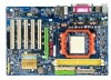
... Chipset LAN Audio Storage O.S Support Memory Expanstion Slots Internal Connectors Socket AM2 for additional 4 USB 2.0/1.1 ports by cable 1 power LED connector 1 Chassis Intrusion connector GA-MF3 Motherboard - 10 - Supports data striping (RAID 0) and mirroring (RAID 1) for Serial ATA Microsoft Windows® 2000/XP 2 DDRII DIMM memory slots (supports up to 4 GB memory) Supports dual channel DDRII 667/533 DIMMs Supports 1.8V DDRII DIMMs 1 AGP slot 5 PCI slots 1 24-pin ATX power connector 1 4-pin ATX 12V power connector 1 floppy connector 2 IDE connectors 2 SATA 1.5Gb/s connectors 1 CPU fan...
... Chipset LAN Audio Storage O.S Support Memory Expanstion Slots Internal Connectors Socket AM2 for additional 4 USB 2.0/1.1 ports by cable 1 power LED connector 1 Chassis Intrusion connector GA-MF3 Motherboard - 10 - Supports data striping (RAID 0) and mirroring (RAID 1) for Serial ATA Microsoft Windows® 2000/XP 2 DDRII DIMM memory slots (supports up to 4 GB memory) Supports dual channel DDRII 667/533 DIMMs Supports 1.8V DDRII DIMMs 1 AGP slot 5 PCI slots 1 24-pin ATX power connector 1 4-pin ATX 12V power connector 1 floppy connector 2 IDE connectors 2 SATA 1.5Gb/s connectors 1 CPU fan...

Manual
Page 11
... Panel I/O I/O Control Hardware Monitor BIOS Additional Features Bundle Software Form Factor 1 PS/2 keyboard port 1 PS/2 mouse port 1 parallel port 2 serial port (COMA&COMB) 4 USB 2.0/1.1 ports 1 RJ-45 port 3 audio jacks (Line In / Line Out / MIC In) IT8716 chip System voltage detection CPU temperature detection CPU / System fan speed detection CPU warning temperature CPU / System fan failure warning Supports CPU Smart Fan function (Note 2) 1 4 Mbit flash ROM Use of licensed AWARD BIOS Supports @BIOS Supports Download Center Supports Q-Flash Supports EasyTune (Note 3) Supports Xpress Install...
... Panel I/O I/O Control Hardware Monitor BIOS Additional Features Bundle Software Form Factor 1 PS/2 keyboard port 1 PS/2 mouse port 1 parallel port 2 serial port (COMA&COMB) 4 USB 2.0/1.1 ports 1 RJ-45 port 3 audio jacks (Line In / Line Out / MIC In) IT8716 chip System voltage detection CPU temperature detection CPU / System fan speed detection CPU warning temperature CPU / System fan failure warning Supports CPU Smart Fan function (Note 2) 1 4 Mbit flash ROM Use of licensed AWARD BIOS Supports @BIOS Supports Download Center Supports Q-Flash Supports EasyTune (Note 3) Supports Xpress Install...

Manual
Page 21
... (Serial ATA Connector) Serial ATA can connect to one IDE device as Master and the other as Slave (for the Serial ATA and install the proper driver in order to two IDE devices (hard drive or optical drive). Please refer to the BIOS setting for information on the IDE device). One IDE connector can provide up to the instructions located on settings, please refer to 150MB/s transfer rate. English 6) IDE1/IDE2 (IDE Connector) An IDE device connects to...
... (Serial ATA Connector) Serial ATA can connect to one IDE device as Master and the other as Slave (for the Serial ATA and install the proper driver in order to two IDE devices (hard drive or optical drive). Please refer to the BIOS setting for information on the IDE device). One IDE connector can provide up to the instructions located on settings, please refer to 150MB/s transfer rate. English 6) IDE1/IDE2 (IDE Connector) An IDE device connects to...

Manual
Page 23
... panel to the F_PANEL connector according to the pin assignment below. PW+ PWSPEAK+ SPEAK- 2 20 1 19 HD+ HD- RESRES+ NC Reset Switch IDE Hard Disk Active LED HD (IDE Hard Disk Active LED) (Blue) SPEAK (Speaker Connector) (Amber) RES (Reset Switch) (Green) PW (Power Switch) (Red) MSG (Message LED/Power/Sleep LED) (Yellow) NC ( Purple) Pin 1: LED anode(+) Pin 2: LED cathode(-) Pin 1: Power Pin 2- Message LED/ Power/ Sleep LED Speaker Connector Power Switch MSG+ MSG- English 10) F_PANEL (Front Panel Jumper) Please connect the power LED, PC speaker, reset switch and power switch...
... panel to the F_PANEL connector according to the pin assignment below. PW+ PWSPEAK+ SPEAK- 2 20 1 19 HD+ HD- RESRES+ NC Reset Switch IDE Hard Disk Active LED HD (IDE Hard Disk Active LED) (Blue) SPEAK (Speaker Connector) (Amber) RES (Reset Switch) (Green) PW (Power Switch) (Red) MSG (Message LED/Power/Sleep LED) (Yellow) NC ( Purple) Pin 1: LED anode(+) Pin 2: LED cathode(-) Pin 1: Power Pin 2- Message LED/ Power/ Sleep LED Speaker Connector Power Switch MSG+ MSG- English 10) F_PANEL (Front Panel Jumper) Please connect the power LED, PC speaker, reset switch and power switch...
Manual
Page 27
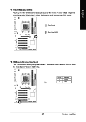
To clear CMOS, temporarily short the two pins. You can check the "Case Opened" status in BIOS Setup. Definition 1 Signal 1 2 GND - 27 - Hardware Installation Default doesn't include the jumper to its default values by this header. English 17) CLR_CMOS (Clear CMOS) You may clear the CMOS data to avoid improper use of this header. Pin No. Open: Normal Short: Clear CMOS 18) CI (Chassis Intrusion, Case Open) This 2-pin connector allows your system to detect if the chassis cover is removed.
To clear CMOS, temporarily short the two pins. You can check the "Case Opened" status in BIOS Setup. Definition 1 Signal 1 2 GND - 27 - Hardware Installation Default doesn't include the jumper to its default values by this header. English 17) CLR_CMOS (Clear CMOS) You may clear the CMOS data to avoid improper use of this header. Pin No. Open: Normal Short: Clear CMOS 18) CI (Chassis Intrusion, Case Open) This 2-pin connector allows your system to detect if the chassis cover is removed.

Manual
Page 30
...-00 : Boot Menu Use < > or < > to select a device, then press enter to accept or enter the sub-menu. GA-MF3 Motherboard - 30 - The BIOS Setup menus described in the BIOS Setup when somehow the system is not stable as figure below) will appear on cards) device. English : Boot Menu Select boot sequence for onboard (or add-on the screen. Boot Menu == Select a Boot First device == Floppy LS120 Hard Disk CDROM ZIP USB-FDD USB-ZIP USB-CDROM USB-HDD Legacy LAN KL:Move Enter :Accept ESC...
...-00 : Boot Menu Use < > or < > to select a device, then press enter to accept or enter the sub-menu. GA-MF3 Motherboard - 30 - The BIOS Setup menus described in the BIOS Setup when somehow the system is not stable as figure below) will appear on cards) device. English : Boot Menu Select boot sequence for onboard (or add-on the screen. Boot Menu == Select a Boot First device == Floppy LS120 Hard Disk CDROM ZIP USB-FDD USB-ZIP USB-CDROM USB-HDD Legacy LAN KL:Move Enter :Accept ESC...
Manual
Page 32
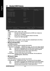
... . IDE/SATA Device Setup. The time is display-only Month The month, Jan. Manual User can manually input the correct settings Access Mode Use this option for automatic device detection. GA-MF3 Motherboard - 32 - Through Dec. is , , , . For example, 1 p.m. IDE Channel 0/1 Master/Slave IDE HDD Auto-Detection Press "Enter" to select this to Sat, determined by the BIOS and is calculated based on the 24-hour military-time clock. English 2-1 Standard CMOS Features CMOS Setup Utility-Copyright (C) 1984-2006 Award Software...
... . IDE/SATA Device Setup. The time is display-only Month The month, Jan. Manual User can manually input the correct settings Access Mode Use this option for automatic device detection. GA-MF3 Motherboard - 32 - Through Dec. is , , , . For example, 1 p.m. IDE Channel 0/1 Master/Slave IDE HDD Auto-Detection Press "Enter" to select this to Sat, determined by the BIOS and is calculated based on the 24-hour military-time clock. English 2-1 Standard CMOS Features CMOS Setup Utility-Copyright (C) 1984-2006 Award Software...

Manual
Page 34
...by LAN. Disabled Disable this menu. USB-HDD Select your boot device priority by USB-HDD. Enabled BIOS searches for onboard (or add-on cards) SCSI, RAID, etc. Disabled BIOS will determine the floppy disk drive installed is 40 or 80 tracks. 360K type is 360K. (Default value) GA-MF3 Motherboard - 34 - English 2-2 Advanced BIOS Features CMOS Setup Utility-Copyright (C) 1984-2006 Award Software Advanced BIOS Features ` Hard Disk Boot Priority First Boot Device Second Boot Device Third Boot Device Boot Up Floppy Seek Password Check Init Display First [Press Enter] [Floppy...
...by LAN. Disabled Disable this menu. USB-HDD Select your boot device priority by USB-HDD. Enabled BIOS searches for onboard (or add-on cards) SCSI, RAID, etc. Disabled BIOS will determine the floppy disk drive installed is 40 or 80 tracks. 360K type is 360K. (Default value) GA-MF3 Motherboard - 34 - English 2-2 Advanced BIOS Features CMOS Setup Utility-Copyright (C) 1984-2006 Award Software Advanced BIOS Features ` Hard Disk Boot Priority First Boot Device Second Boot Device Third Boot Device Boot Up Floppy Seek Password Check Init Display First [Press Enter] [Floppy...
Manual
Page 38
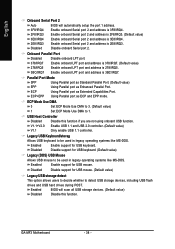
... Onboard Serial Port 2 Auto BIOS will scan all USB storage devices. (Default value) Disabled Disable this function if you are not using onboard USB function. Onboard Parallel Port Disabled Disable onboard LPT port. 378/IRQ7 Enable onboard LPT port and address is 378/IRQ7. (Default value) 278/IRQ5 Enable onboard LPT port and address is 278/IRQ5. 3BC/IRQ7 Enable onboard LPT port and address is 2E8/IRQ3. Legacy USB Keyboard/storag Allows USB keyboard to 1. GA-MF3 Motherboard - 38 - Enabled Enable support for USB mouse. Parallel Port Mode SPP EPP ECP ECP+EPP Using...
... Onboard Serial Port 2 Auto BIOS will scan all USB storage devices. (Default value) Disabled Disable this function if you are not using onboard USB function. Onboard Parallel Port Disabled Disable onboard LPT port. 378/IRQ7 Enable onboard LPT port and address is 378/IRQ7. (Default value) 278/IRQ5 Enable onboard LPT port and address is 278/IRQ5. 3BC/IRQ7 Enable onboard LPT port and address is 2E8/IRQ3. Legacy USB Keyboard/storag Allows USB keyboard to 1. GA-MF3 Motherboard - 38 - Enabled Enable support for USB mouse. Parallel Port Mode SPP EPP ECP ECP+EPP Using...

Manual
Page 44
... Setup Change/Set/Disable Password When you try to assist you can enter Setup freely. You will boot and you in Advance BIOS Features Menu, you will be prompted for BIOS and Chipset Features which the system automatically detects. 2-9 Set Supervisor/User Password CMOS Setup Utility-Copyright (C) 1984-2006 Award Software ` Standard CMOS Features ` Advanced BIOS Features ` Integrated Peripherals ` Power Management Setup ` PnP/PCI ConfiguratioEnsnter Password: ` PC Health Status ` MB Intelligent Tweaker(M.I .T.) Load Optimized Defaults Set Supervisor Password Set User Password Load...
... Setup Change/Set/Disable Password When you try to assist you can enter Setup freely. You will boot and you in Advance BIOS Features Menu, you will be prompted for BIOS and Chipset Features which the system automatically detects. 2-9 Set Supervisor/User Password CMOS Setup Utility-Copyright (C) 1984-2006 Award Software ` Standard CMOS Features ` Advanced BIOS Features ` Integrated Peripherals ` Power Management Setup ` PnP/PCI ConfiguratioEnsnter Password: ` PC Health Status ` MB Intelligent Tweaker(M.I .T.) Load Optimized Defaults Set Supervisor Password Set User Password Load...
Manual
Page 52
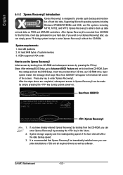
... the settings and exit the BIOS Setup. Boot from CD/DVD: Press any key to enter Xpress Recovery2. GA-MF3 D12 . . . . :BIOS Setup/Q-Flash, : Xpress Recovery2, : Boot Menu 10/12/2006-nForce-6A61CG0PC-00 : Xpress Recovery2 1. If you have already entered Xpress Recovery2 by booting from CD-ROM for the first time, it will stay permanent in the future. 2. System storage capacity and the reading/writing speed of the hard disk...
... the settings and exit the BIOS Setup. Boot from CD/DVD: Press any key to enter Xpress Recovery2. GA-MF3 D12 . . . . :BIOS Setup/Q-Flash, : Xpress Recovery2, : Boot Menu 10/12/2006-nForce-6A61CG0PC-00 : Xpress Recovery2 1. If you have already entered Xpress Recovery2 by booting from CD-ROM for the first time, it will stay permanent in the future. 2. System storage capacity and the reading/writing speed of the hard disk...

Manual
Page 55
... Load Fail-Safe Defaults Load Optimized Defaults Set Supervisor Password Set User Password Save & Exit Setup Exit Without Saving F3: Change Language F10: Save & Exit Setup Time, Date, Hard Disk Type... Blocking a task and pressing Enter key on your keyboard and then Y button to enter the Dual BIOS/Q-Flash utility. Task menu for Dual BIOS utility Task menu for Q-FlashTM utility Dual BIOS Utility Boot From Main Bios Main ROM Type/Size SST 49LF003A Backup ROM Type/Size SST 49LF003A 512K 512K Wide Range Protection Disable Boot From Main Bios Auto Recovery Enable Halt On Error Disable...
... Load Fail-Safe Defaults Load Optimized Defaults Set Supervisor Password Set User Password Save & Exit Setup Exit Without Saving F3: Change Language F10: Save & Exit Setup Time, Date, Hard Disk Type... Blocking a task and pressing Enter key on your keyboard and then Y button to enter the Dual BIOS/Q-Flash utility. Task menu for Dual BIOS utility Task menu for Q-FlashTM utility Dual BIOS Utility Boot From Main Bios Main ROM Type/Size SST 49LF003A Backup ROM Type/Size SST 49LF003A 512K 512K Wide Range Protection Disable Boot From Main Bios Auto Recovery Enable Halt On Error Disable...

Manual
Page 57
...Enter : Run :Move ESC:Reset F10:Power Off After system reboots, you may find the BIOS version on your boot screen becomes the one you exit Q-Flash. Appendix Dual BIOS Utility Boot From Main Bios Main ROM Type/Size SST 49LF003A Backup ROM Type/Size SST 49LF003A 512K 512K Wide Range Protection Disable Boot From Main Bios AutoARreecyoovuersyure EtonaRbEleSET ? Halt On Error Disable [ECntoepry] tMoacionnRtiOnuMreDoarta[EtoscB]atcokuapbort... Halt On Error Disable CPopleyasMe apirneRssOaMnyDkaetya tto cBoanctkiunpue Load Default Settings Save Settings to CMOS Q-Flash Utility Load...
...Enter : Run :Move ESC:Reset F10:Power Off After system reboots, you may find the BIOS version on your boot screen becomes the one you exit Q-Flash. Appendix Dual BIOS Utility Boot From Main Bios Main ROM Type/Size SST 49LF003A Backup ROM Type/Size SST 49LF003A 512K 512K Wide Range Protection Disable Boot From Main Bios AutoARreecyoovuersyure EtonaRbEleSET ? Halt On Error Disable [ECntoepry] tMoacionnRtiOnuMreDoarta[EtoscB]atcokuapbort... Halt On Error Disable CPopleyasMe apirneRssOaMnyDkaetya tto cBoanctkiunpue Load Default Settings Save Settings to CMOS Q-Flash Utility Load...
Manual
Page 58
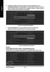
.../PCI Configurations Load Optimized Defaults (SYet/NU)s?eYr Password PC Health Status Save & Exit Setup MB Intelligent Tweaker(M.I.T.) Exit Without Saving ESC: Quit F8: Dual BIOS/Q-Flash F3: Change Language F10: Save & Exit Setup Load Optimized Defaults Press Y on your keyboard to enter BIOS menu after BIOS has been upgraded. Part Two: Updating BIOS with Q-FlashTM Utility on your keyboard to load BIOS Optimized Defaults. Therefore, we highly recommend reloading the BIOS defaults after system reboots. CMOS Setup Utility-Copyright (C) 1984-2004 Award Software Standard CMOS...
.../PCI Configurations Load Optimized Defaults (SYet/NU)s?eYr Password PC Health Status Save & Exit Setup MB Intelligent Tweaker(M.I.T.) Exit Without Saving ESC: Quit F8: Dual BIOS/Q-Flash F3: Change Language F10: Save & Exit Setup Load Optimized Defaults Press Y on your keyboard to enter BIOS menu after BIOS has been upgraded. Part Two: Updating BIOS with Q-FlashTM Utility on your keyboard to load BIOS Optimized Defaults. Therefore, we highly recommend reloading the BIOS defaults after system reboots. CMOS Setup Utility-Copyright (C) 1984-2004 Award Software Standard CMOS...

Manual
Page 64
CMOS Setup Utility-Copyright (C) 1984-2005 Award Software Integrated Peripherals RAID Config On-Chip Primary PCI IDE On-Chip Secondary PCI IDE IDE DMA transfer Serial-ATA 2(Internal PHY) SATA DMA transfer USB Memory Type AC97 Audio On-Chip LAN(nVIDIA) OnBoard LAN Boot ROM Onboard Serial Port 1 Onboard Serial Port 2 Onboard Parallel Port Parallel Port Mode x ECP Mode Use DMA USB Host Controller Legacy USB Keyboard/Storag Legacy (DOS) USB Mouse Legacy USB storage detect [Press Enter] [Enabled] [Enabled] [Enabled] [Enabled] [Enabled] [SHADOW] [Auto] [Auto] [Disabled] [3F8/IRQ4] [2F8/IRQ3] [378/...
CMOS Setup Utility-Copyright (C) 1984-2005 Award Software Integrated Peripherals RAID Config On-Chip Primary PCI IDE On-Chip Secondary PCI IDE IDE DMA transfer Serial-ATA 2(Internal PHY) SATA DMA transfer USB Memory Type AC97 Audio On-Chip LAN(nVIDIA) OnBoard LAN Boot ROM Onboard Serial Port 1 Onboard Serial Port 2 Onboard Parallel Port Parallel Port Mode x ECP Mode Use DMA USB Host Controller Legacy USB Keyboard/Storag Legacy (DOS) USB Mouse Legacy USB storage detect [Press Enter] [Enabled] [Enabled] [Enabled] [Enabled] [Enabled] [SHADOW] [Auto] [Auto] [Disabled] [3F8/IRQ4] [2F8/IRQ3] [378/...

Manual
Page 69
... users without a startup disk: Use an alternative system and insert the GIGABYTE motherboard driver CD-ROM. At the D:\> prompt, type the following two commands. See the instructions below about how to copy the driver in MS-DOS mode . (Note) Prepare a startup disk that in Figure 11, press E to select (E) nVIDIA nForce3 Series Raid (XP) if you wish to install Windows XP (32-bit). Press 0 to the CD-ROM drive...
... users without a startup disk: Use an alternative system and insert the GIGABYTE motherboard driver CD-ROM. At the D:\> prompt, type the following two commands. See the instructions below about how to copy the driver in MS-DOS mode . (Note) Prepare a startup disk that in Figure 11, press E to select (E) nVIDIA nForce3 Series Raid (XP) if you wish to install Windows XP (32-bit). Press 0 to the CD-ROM drive...

Manual
Page 70
... Figure 14 GA-MF3 Motherboard - 70 - Figure 13 Step 2: When a screen similar to that you have prepared the SATA driver disk and configured BIOS settings, you are ready to install a third party SCSI or RAID driver" message (Figure 13). After pressing F6, there will load support for the following is an example of one or more mass storage devices installed in your system to boot from a mass storage device manufacturer, or...
... Figure 14 GA-MF3 Motherboard - 70 - Figure 13 Step 2: When a screen similar to that you have prepared the SATA driver disk and configured BIOS settings, you are ready to install a third party SCSI or RAID driver" message (Figure 13). After pressing F6, there will load support for the following is an example of one or more mass storage devices installed in your system to boot from a mass storage device manufacturer, or...

Manual
Page 72
... set up Windows XP now, press ENTER. After that hard drive. S=Specify Additional Device ENTER=Continue F3=Exit Figure 17 After the SATA controller driver installation is completed, you can proceed with Windows, press ENTER. To repair a Windows XP installation using Recovery Console, press R. Enter= Continue R=Repair F3=Exit Figure 18 (Note: Each time you add a new hard drive to a RAID array, the RAID driver will have to be installed.) GA-MF3 Motherboard - 72 - English Step 4: When the next screen...
... set up Windows XP now, press ENTER. After that hard drive. S=Specify Additional Device ENTER=Continue F3=Exit Figure 17 After the SATA controller driver installation is completed, you can proceed with Windows, press ENTER. To repair a Windows XP installation using Recovery Console, press R. Enter= Continue R=Repair F3=Exit Figure 18 (Note: Each time you add a new hard drive to a RAID array, the RAID driver will have to be installed.) GA-MF3 Motherboard - 72 - English Step 4: When the next screen...
Manual
Page 73
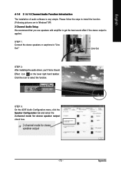
Line Out STEP 2: After installing the audio driver, you use speakers with amplifier to install the function. (Following pictures are in Windows® XP) 2 Channel Audio Setup We recommend that you 'll find a Sound Effect icon on the lower right hand taskbar. STEP 3: On the AC97 Audio Configuration menu, click the Speaker Configuration tab and select the 2-channel mode for stereo speaker output check box. - 73 - Please follow the steps...
Line Out STEP 2: After installing the audio driver, you use speakers with amplifier to install the function. (Following pictures are in Windows® XP) 2 Channel Audio Setup We recommend that you 'll find a Sound Effect icon on the lower right hand taskbar. STEP 3: On the AC97 Audio Configuration menu, click the Speaker Configuration tab and select the 2-channel mode for stereo speaker output check box. - 73 - Please follow the steps...

Manual
Page 79
... on a specific motherboard model, please log on power. 6. Take out the battery gently and put it aside for about 1 minute (Or you will be able to the Clear CMOS steps in previous BIOS after updating BIOS. Save changes and reboot the system. Answer: In some options that 's why the light is kept on -board battery to leak voltage to makethem short for ? AWARD BIOS Beep Codes 1 short: System boots successfully 2 short: CMOS setting error 1 long 1 short: DRAM or M/B error 1 long 2 short: Monitor or display card error 1 long 3 short: Keyboard error 1 long 9 short: BIOS ROM error...
... on a specific motherboard model, please log on power. 6. Take out the battery gently and put it aside for about 1 minute (Or you will be able to the Clear CMOS steps in previous BIOS after updating BIOS. Save changes and reboot the system. Answer: In some options that 's why the light is kept on -board battery to leak voltage to makethem short for ? AWARD BIOS Beep Codes 1 short: System boots successfully 2 short: CMOS setting error 1 long 1 short: DRAM or M/B error 1 long 2 short: Monitor or display card error 1 long 3 short: Keyboard error 1 long 9 short: BIOS ROM error...


