Manual
Page 1
GA-MA78LMT-US2H AM3 socket motherboard for AMD Phenom™ II processor/ AMD Athlon™ II processor User's Manual Rev. 1101 12ME-MA78LMT-1101R
GA-MA78LMT-US2H AM3 socket motherboard for AMD Phenom™ II processor/ AMD Athlon™ II processor User's Manual Rev. 1101 12ME-MA78LMT-1101R
Manual
Page 2
Motherboard GA-MA78LMT-US2H Dec. 18, 2009 Motherboard GA-MA78LMT-US2H Dec. 18, 2009
Motherboard GA-MA78LMT-US2H Dec. 18, 2009 Motherboard GA-MA78LMT-US2H Dec. 18, 2009
Manual
Page 3
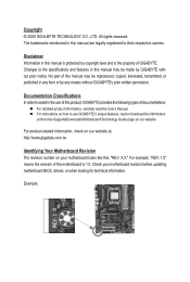
..., transmitted, or published in this : "REV: X.X." For example, "REV: 1.0" means the revision of the motherboard is protected by GIGABYTE without GIGABYTE's prior written permission. The trademarks mentioned in any form or by any means without prior notice. For product-related ... product information, carefully read or download the information on/from the Support&Downloads\Motherboard\Technology Guide page on how to their respective owners. Example: Disclaimer Information in the use GIGABYTE's unique features, read the User's Manual. For instructions on our...
..., transmitted, or published in this : "REV: X.X." For example, "REV: 1.0" means the revision of the motherboard is protected by GIGABYTE without GIGABYTE's prior written permission. The trademarks mentioned in any form or by any means without prior notice. For product-related ... product information, carefully read or download the information on/from the Support&Downloads\Motherboard\Technology Guide page on how to their respective owners. Example: Disclaimer Information in the use GIGABYTE's unique features, read the User's Manual. For instructions on our...
Manual
Page 4
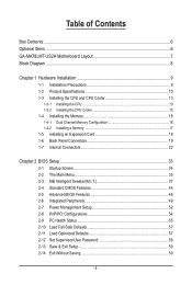
Table of Contents Box Contents...6 Optional Items...6 GA-MA78LMT-US2H Motherboard Layout 7 Block Diagram...8 Chapter 1 Hardware Installation 9 1-1 Installation Precautions 9 1-2 Product Specifications 10 1-3 Installing the CPU and CPU Cooler 13 1-3-1 Installing the CPU 13 1-3-2 Installing the CPU ...
Table of Contents Box Contents...6 Optional Items...6 GA-MA78LMT-US2H Motherboard Layout 7 Block Diagram...8 Chapter 1 Hardware Installation 9 1-1 Installation Precautions 9 1-2 Product Specifications 10 1-3 Installing the CPU and CPU Cooler 13 1-3-1 Installing the CPU 13 1-3-2 Installing the CPU ...
Manual
Page 6
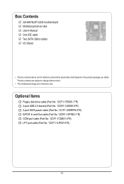
The box contents are for reference only. Box Contents GA-MA78LMT-US2H motherboard Motherboard driver disk User's Manual One IDE cable Two SATA 3Gb/s cables I/O Shield • The box contents above are subject to change without notice. • The motherboard image is for reference only and the actual items shall depend on the product package you obtain...
The box contents are for reference only. Box Contents GA-MA78LMT-US2H motherboard Motherboard driver disk User's Manual One IDE cable Two SATA 3Gb/s cables I/O Shield • The box contents above are subject to change without notice. • The motherboard image is for reference only and the actual items shall depend on the product package you obtain...
Manual
Page 7
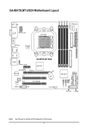
GA-MA78LMT-US2H Motherboard Layout DDR3_1 DDR3_2 DDR3_3 DDR3_4 M_BIOS IT8718 ATX DVI VGA KB(Note)_USB ATX_12V_2X4 Socket AM3 B_BIOS CI HDMI USB ESATA OPTICAL CPU_FAN FDD USB LAN AUDIO F_AUDIO PCIEX1 GA-MA78LMT-US2H AMD 760G NB_FAN PCIEX16 RTL8111D PCI1 BAT CD_IN CODEC PCI2 CLR_CMOS SPDIF_IO COM SYS_FAN LPT IDE AMD SB710 SATA2_4 F_USB1 F_USB2 F_USB3 SATA2_1 SATA2_3 SATA2_0 SATA2_2 PWR_LED F_PANEL (Note) Use this port to connect a PS/2 keyboard or PS/2 mouse. - 7 -
GA-MA78LMT-US2H Motherboard Layout DDR3_1 DDR3_2 DDR3_3 DDR3_4 M_BIOS IT8718 ATX DVI VGA KB(Note)_USB ATX_12V_2X4 Socket AM3 B_BIOS CI HDMI USB ESATA OPTICAL CPU_FAN FDD USB LAN AUDIO F_AUDIO PCIEX1 GA-MA78LMT-US2H AMD 760G NB_FAN PCIEX16 RTL8111D PCI1 BAT CD_IN CODEC PCI2 CLR_CMOS SPDIF_IO COM SYS_FAN LPT IDE AMD SB710 SATA2_4 F_USB1 F_USB2 F_USB3 SATA2_1 SATA2_3 SATA2_0 SATA2_2 PWR_LED F_PANEL (Note) Use this port to connect a PS/2 keyboard or PS/2 mouse. - 7 -
Manual
Page 9
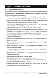
... within an electrostatic shielding container. • Before unplugging the power supply cable from the power outlet before installing or removing the motherboard or other hardware components. • When connecting hardware components to the internal connectors on the computer power during the installation process ... for warranty validation. • Always remove the AC power by your hardware components are connected. • To prevent damage to the motherboard, do not have an ESD wrist strap, keep your hands dry and first touch a metal object to eliminate static electricity. •...
... within an electrostatic shielding container. • Before unplugging the power supply cable from the power outlet before installing or removing the motherboard or other hardware components. • When connecting hardware components to the internal connectors on the computer power during the installation process ... for warranty validation. • Always remove the AC power by your hardware components are connected. • To prevent damage to the motherboard, do not have an ESD wrist strap, keep your hands dry and first touch a metal object to eliminate static electricity. •...
Manual
Page 12
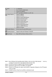
... CPU/system fan speed control function is supported will depend on the CPU/system cooler you install. (Note 5) Available functions in EasyTune may differ by motherboard model. Hardware Installation - 12 -
... CPU/system fan speed control function is supported will depend on the CPU/system cooler you install. (Note 5) Available functions in EasyTune may differ by motherboard model. Hardware Installation - 12 -

Manual
Page 13
... standard requirements for the latest CPU support list.) • Always turn on the computer if the CPU cooler is not recommended that the motherboard supports the CPU. (Go to GIGABYTE's website for the peripherals. age of the Socket AM3 Socket A Small Triangle Marking Denotes CPU Pin One AM3 CPU - 13 - It is...
... standard requirements for the latest CPU support list.) • Always turn on the computer if the CPU cooler is not recommended that the motherboard supports the CPU. (Go to GIGABYTE's website for the peripherals. age of the Socket AM3 Socket A Small Triangle Marking Denotes CPU Pin One AM3 CPU - 13 - It is...
Manual
Page 14
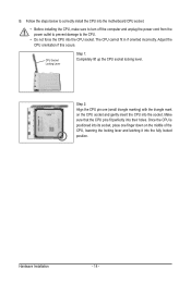
... CPU socket locking lever. Hardware Installation - 14 - Adjust the CPU orientation if this occurs. Follow the steps below to correctly install the CPU into the motherboard CPU socket. • Before installing the CPU, make sure to turn off the computer and unplug the power cord from the power outlet to prevent...
... CPU socket locking lever. Hardware Installation - 14 - Adjust the CPU orientation if this occurs. Follow the steps below to correctly install the CPU into the motherboard CPU socket. • Before installing the CPU, make sure to turn off the computer and unplug the power cord from the power outlet to prevent...
Manual
Page 15
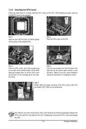
On the other side,push straight down on the the CPU cooler clip to hook it to the CPU fan header (CPU_FAN) on the motherboard. Step 4: Turn the cam handle from the left side to the right side (as the example.) Step 1: Apply an even and thin layer of ...- 15 - Hardware Installation 1-3-2 Installing the CPU Cooler Follow the steps below to correctly install the CPU cooler on the CPU. (The following procedure uses the GIGABYTE cooler as the picture above shows) to lock into place. (Refer to your CPU cooler installation manual for instructions on installing the cooler.) Step 5: Finally...
On the other side,push straight down on the the CPU cooler clip to hook it to the CPU fan header (CPU_FAN) on the motherboard. Step 4: Turn the cam handle from the left side to the right side (as the example.) Step 1: Apply an even and thin layer of ...- 15 - Hardware Installation 1-3-2 Installing the CPU Cooler Follow the steps below to correctly install the CPU cooler on the CPU. (The following procedure uses the GIGABYTE cooler as the picture above shows) to lock into place. (Refer to your CPU cooler installation manual for instructions on installing the cooler.) Step 5: Finally...
Manual
Page 16
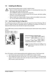
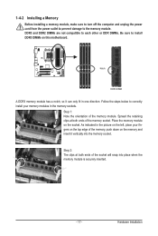
...and capacity of the same capacity, brand, speed, and chips be enabled if only one direction. A memory module can be used. (Go to GIGABYTE's website for optimum performance. DS/SS DS/SS Four Modules DS/SS DS/SS DS/SS DS/SS (SS=Single-Sided, DS=Double-Sided,.... Hardware Installation - 16 - The four DDR3 memory sockets are to insert the memory, switch the direction. 1-4-1 Dual Channel Memory Configuration This motherboard provides four DDR3 memory sockets and supports Dual Channel Technology. It is recommended that memory of the same capacity, brand, speed, and chips be...
...and capacity of the same capacity, brand, speed, and chips be enabled if only one direction. A memory module can be used. (Go to GIGABYTE's website for optimum performance. DS/SS DS/SS Four Modules DS/SS DS/SS DS/SS DS/SS (SS=Single-Sided, DS=Double-Sided,.... Hardware Installation - 16 - The four DDR3 memory sockets are to insert the memory, switch the direction. 1-4-1 Dual Channel Memory Configuration This motherboard provides four DDR3 memory sockets and supports Dual Channel Technology. It is recommended that memory of the same capacity, brand, speed, and chips be...
Manual
Page 17
... of the memory socket. DDR3 and DDR2 DIMMs are not compatible to each other or DDR DIMMs. Be sure to install DDR3 DIMMs on this motherboard. Step 1: Note the orientation of the socket will snap into the memory socket. Spread the retaining clips at both ends of the memory, push down...
... of the memory socket. DDR3 and DDR2 DIMMs are not compatible to each other or DDR DIMMs. Be sure to install DDR3 DIMMs on this motherboard. Step 1: Note the orientation of the socket will snap into the memory socket. Spread the retaining clips at both ends of the memory, push down...
Manual
Page 18
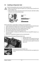
... card until it is fully seated in the expansion slot. 1. If necessary, go to BIOS Setup to install an expansion card: • Make sure the motherboard supports the expansion card. Turn on the slot and then lift the card straight out from the PCIEX16_1 slot: Gently push back on the lever...
... card until it is fully seated in the expansion slot. 1. If necessary, go to BIOS Setup to install an expansion card: • Make sure the motherboard supports the expansion card. Turn on the slot and then lift the card straight out from the PCIEX16_1 slot: Gently push back on the lever...
Manual
Page 20
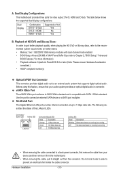
Dual Display Configurations: This motherboard provides three ports for more information) • Playback software: CyberLink PowerDVD 8.0 or later (Note: Please ensure Hardware Acceleration is compatible with dual channel mode enabled &#... monitor(s) Optical S/PDIF Out Connector This connector provides digital audio out to an external audio system that your device and then remove it from the motherboard. • When removing the cable, pull it side to side to the recommended system requirements (or better) below shows the supported dual display configurations. The...
Dual Display Configurations: This motherboard provides three ports for more information) • Playback software: CyberLink PowerDVD 8.0 or later (Note: Please ensure Hardware Acceleration is compatible with dual channel mode enabled &#... monitor(s) Optical S/PDIF Out Connector This connector provides digital audio out to an external audio system that your device and then remove it from the motherboard. • When removing the cable, pull it side to side to the recommended system requirements (or better) below shows the supported dual display configurations. The...
Manual
Page 22
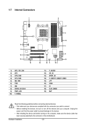
...) CD_IN 13) SPDIF_IO 14) F_USB1/F_USB2/F_USB3 15) LPT 16) COM 17) CI 18) CLR_CMOS 19) BAT Read the following guidelines before turning on the motherboard. Hardware Installation - 22 - Unplug the power cord from the power outlet to prevent damage to the devices. • After installing the device and before connecting...
...) CD_IN 13) SPDIF_IO 14) F_USB1/F_USB2/F_USB3 15) LPT 16) COM 17) CI 18) CLR_CMOS 19) BAT Read the following guidelines before turning on the motherboard. Hardware Installation - 22 - Unplug the power cord from the power outlet to prevent damage to the devices. • After installing the device and before connecting...
Manual
Page 23
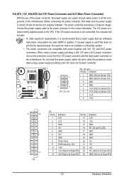
... power connector possesses a foolproof design. Before connecting the power connector, first make sure the power supply is turned off and all the components on the motherboard. Definition 1 GND (Only for 2x4-pin 12V) 2 GND (Only for 2x4-pin 12V) 3 GND 4 GND 5 +12V (Only for 2x4-pin 12V) 6 ... providing a 2x4 12V and a 2x12 power connector, remove the protective covers from the 12V power connector and the main power connector on the motherboard. The 12V power connector mainly supplies power to the power connector in the correct orientation. If the 12V power connector is not connected, the...
... power connector possesses a foolproof design. Before connecting the power connector, first make sure the power supply is turned off and all the components on the motherboard. Definition 1 GND (Only for 2x4-pin 12V) 2 GND (Only for 2x4-pin 12V) 3 GND 4 GND 5 +12V (Only for 2x4-pin 12V) 6 ... providing a 2x4 12V and a 2x12 power connector, remove the protective covers from the 12V power connector and the main power connector on the motherboard. The 12V power connector mainly supplies power to the power connector in the correct orientation. If the 12V power connector is not connected, the...
Manual
Page 24
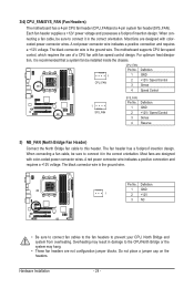
Hardware Installation - 24 - A red power connector wire indicates a positive connection and requires a +12V voltage. The motherboard supports CPU fan speed control, which requires the use of a CPU fan with colorcoded power connector wires. A red power connector wire indicates a positive connection and ... wires. Overheating may result in damage to connect it in the correct orientation. The fan header has a foolproof insertion design. 3/4) CPU_FAN/SYS_FAN (Fan Headers) The motherboard has a 4-pin CPU fan header (CPU_FAN)and a 4-pin system fan header(SYS_FAN).
Hardware Installation - 24 - A red power connector wire indicates a positive connection and requires a +12V voltage. The motherboard supports CPU fan speed control, which requires the use of a CPU fan with colorcoded power connector wires. A red power connector wire indicates a positive connection and ... wires. Overheating may result in damage to connect it in the correct orientation. The fan header has a foolproof insertion design. 3/4) CPU_FAN/SYS_FAN (Fan Headers) The motherboard has a 4-pin CPU fan header (CPU_FAN)and a 4-pin system fan header(SYS_FAN).
Manual
Page 28
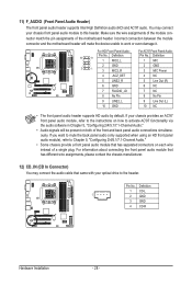
...2/4/5.1/7.1-Channel Audio." • Some chassis provide a front panel audio module that has separated connectors on each wire instead of the motherboard header. You may connect the audio cable that has different wire assignments, please contact the chassis manufacturer. 12) CD_IN (CD ...it. Definition 1 CD-L 1 2 GND 3 GND 4 CD-R Hardware Installation - 28 - Incorrect connection between the module connector and the motherboard header will be present on how to activate AC'97 functionality via the audio software in Chapter 5, "Configuring 2/4/5.1/7.1-Channel Audio." • ...
...2/4/5.1/7.1-Channel Audio." • Some chassis provide a front panel audio module that has separated connectors on each wire instead of the motherboard header. You may connect the audio cable that has different wire assignments, please contact the chassis manufacturer. 12) CD_IN (CD ...it. Definition 1 CD-L 1 2 GND 3 GND 4 CD-R Hardware Installation - 28 - Incorrect connection between the module connector and the motherboard header will be present on how to activate AC'97 functionality via the audio software in Chapter 5, "Configuring 2/4/5.1/7.1-Channel Audio." • ...
Manual
Page 31
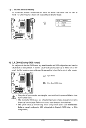
...1 Signal 2 GND 18) CLR_CMOS (Clearing CMOS Jumper) Use this jumper to factory defaults. 17) CI (Chassis Intrusion Header) This motherboard provides a chassis detection feature that detects if the chassis cover has been removed. Pin No. date information and BIOS configurations) and reset... the CMOS values to clear the CMOS values (e.g. Hardware Installation Failure to do so may cause damage to the motherboard. • After system restart, go to BIOS Setup to load factory defaults (select Load Optimized Defaults) or manually configure the BIOS settings...
...1 Signal 2 GND 18) CLR_CMOS (Clearing CMOS Jumper) Use this jumper to factory defaults. 17) CI (Chassis Intrusion Header) This motherboard provides a chassis detection feature that detects if the chassis cover has been removed. Pin No. date information and BIOS configurations) and reset... the CMOS values to clear the CMOS values (e.g. Hardware Installation Failure to do so may cause damage to the motherboard. • After system restart, go to BIOS Setup to load factory defaults (select Load Optimized Defaults) or manually configure the BIOS settings...


