Manual
Page 3
... use of this product, GIGABYTE provides the following types of documentations: For detailed product information, carefully read or download the information on/from the Support&Downloads\Motherboard\Technology Guide page on your motherboard revision before updating motherboard BIOS, drivers, or when looking for technical information. Documentation Classifications In order to assist in the use GIGABYTE's unique features, read the User's Manual. For instructions on how to the specifications...
... use of this product, GIGABYTE provides the following types of documentations: For detailed product information, carefully read or download the information on/from the Support&Downloads\Motherboard\Technology Guide page on your motherboard revision before updating motherboard BIOS, drivers, or when looking for technical information. Documentation Classifications In order to assist in the use GIGABYTE's unique features, read the User's Manual. For instructions on how to the specifications...
Manual
Page 4
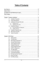
... of Contents Box Contents...6 Optional Items...6 GA-MA78LMT-US2H Motherboard Layout 7 Block Diagram...8 Chapter 1 Hardware Installation 9 1-1 Installation Precautions 9 1-2 Product Specifications 10 1-3 Installing the CPU and CPU Cooler 13 1-3-1 Installing the CPU 13 1-3-2 Installing the CPU Cooler 15 1-4 Installing the Memory 16 1-4-1 Dual Channel Memory Configuration 16 1-4-2 Installing a Memory 17 1-5 Installing an Expansion Card 18 1-6 Back Panel Connectors 19 1-7 Internal Connectors 22 Chapter 2 BIOS Setup 33 2-1 Startup Screen 34 2-2 The Main Menu 35 2-3 MB Intelligent...
... of Contents Box Contents...6 Optional Items...6 GA-MA78LMT-US2H Motherboard Layout 7 Block Diagram...8 Chapter 1 Hardware Installation 9 1-1 Installation Precautions 9 1-2 Product Specifications 10 1-3 Installing the CPU and CPU Cooler 13 1-3-1 Installing the CPU 13 1-3-2 Installing the CPU Cooler 15 1-4 Installing the Memory 16 1-4-1 Dual Channel Memory Configuration 16 1-4-2 Installing a Memory 17 1-5 Installing an Expansion Card 18 1-6 Back Panel Connectors 19 1-7 Internal Connectors 22 Chapter 2 BIOS Setup 33 2-1 Startup Screen 34 2-2 The Main Menu 35 2-3 MB Intelligent...
Manual
Page 10
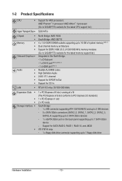
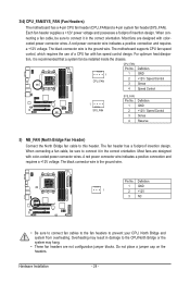
...1) Dual channel memory architecture Support for DDR3 1666 (O.C.)/1333/1066 MHz memory modules (Go to GIGABYTE's website for the latest memory support list.) Integrated in the North Bridge: - 1 x D-Sub port - 1 x DVI-D port (Note 2) (Note 3) - 1 x HDMI port (Note 3) Realtek ALC888B codec High Definition Audio 2/4/5.1/7.1-channel Support for S/PDIF In/Out Support for SATA RAID 0, RAID 1, RAID 10, and JBOD iTE IT8718 chip: - 1 x floppy disk drive connector supporting up to 1 floppy disk drive Hardware Installation - 10 - Support for CD In LAN RTL8111D chip...
...1) Dual channel memory architecture Support for DDR3 1666 (O.C.)/1333/1066 MHz memory modules (Go to GIGABYTE's website for the latest memory support list.) Integrated in the North Bridge: - 1 x D-Sub port - 1 x DVI-D port (Note 2) (Note 3) - 1 x HDMI port (Note 3) Realtek ALC888B codec High Definition Audio 2/4/5.1/7.1-channel Support for S/PDIF In/Out Support for SATA RAID 0, RAID 1, RAID 10, and JBOD iTE IT8718 chip: - 1 x floppy disk drive connector supporting up to 1 floppy disk drive Hardware Installation - 10 - Support for CD In LAN RTL8111D chip...
Manual
Page 18
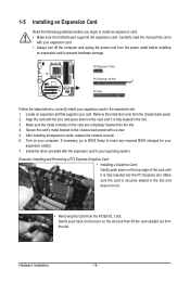
... the manual that supports your card. Locate an expansion slot that came with the expansion card in the slot. 3. After installing all expansion cards, replace the chassis cover(s). 6. If necessary, go to BIOS Setup to make any required BIOS changes for your computer. Install the driver provided with your operating system. Secure the card's metal bracket to the chassis back panel with the slot, and press down on the slot and then...
... the manual that supports your card. Locate an expansion slot that came with the expansion card in the slot. 3. After installing all expansion cards, replace the chassis cover(s). 6. If necessary, go to BIOS Setup to make any required BIOS changes for your computer. Install the driver provided with your operating system. Secure the card's metal bracket to the chassis back panel with the slot, and press down on the slot and then...
Manual
Page 24
... fan headers are designed with color-coded power connector wires. Definition 1 GND 1 2 +12V 3 NC • Be sure to connect fan cables to the fan headers to this header. Hardware Installation - 24 - A red power connector wire indicates a positive connection and requires a +12V voltage. For optimum heat dissipation, it in the correct orientation. When connecting a fan cable, be installed inside the chassis. 3/4) CPU_FAN/SYS_FAN (Fan Headers) The motherboard has a 4-pin CPU fan header (CPU_FAN)and a 4-pin system fan header(SYS_FAN). Most fans are not configuration jumper...
... fan headers are designed with color-coded power connector wires. Definition 1 GND 1 2 +12V 3 NC • Be sure to connect fan cables to the fan headers to this header. Hardware Installation - 24 - A red power connector wire indicates a positive connection and requires a +12V voltage. For optimum heat dissipation, it in the correct orientation. When connecting a fan cable, be installed inside the chassis. 3/4) CPU_FAN/SYS_FAN (Fan Headers) The motherboard has a 4-pin CPU fan header (CPU_FAN)and a 4-pin system fan header(SYS_FAN). Most fans are not configuration jumper...
Manual
Page 34
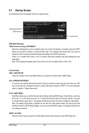
.... The system will display a message during the POST. BIOS Setup - 34 - Note: This message will still be used for subsequent access to enter BIOS Setup first. Motherboard Model BIOS Version Award Modular BIOS v6.00PG, An Energy Star Ally Copyright (C) 1984-2009, Award Software, Inc. Press to enable AHCI mode or to its default values, the monitor will directly boot from the device configured in time. You can be based on BIOS Setup settings. GA-MA78LMT-US2H D1c . . . . : BIOS Setup : XpressRecovery2 : Boot Menu : Qflash 12...
.... The system will display a message during the POST. BIOS Setup - 34 - Note: This message will still be used for subsequent access to enter BIOS Setup first. Motherboard Model BIOS Version Award Modular BIOS v6.00PG, An Energy Star Ally Copyright (C) 1984-2009, Award Software, Inc. Press to enable AHCI mode or to its default values, the monitor will directly boot from the device configured in time. You can be based on BIOS Setup settings. GA-MA78LMT-US2H D1c . . . . : BIOS Setup : XpressRecovery2 : Boot Menu : Qflash 12...
Manual
Page 36
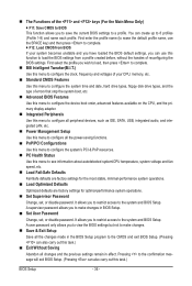
... CPU, memory, etc. Standard CMOS Features Use this menu to configure the system time and date, hard drive types, floppy disk drive types, and the type of errors that stop the system boot, etc. Advanced BIOS Features Use this menu to configure the device boot order, advanced features available on the CPU, and the primary display adapter. Integrated Peripherals Use this menu to configure all peripheral devices, such as IDE, SATA, USB, integrated audio, and integrated LAN, etc. Power Management Setup Use...
... CPU, memory, etc. Standard CMOS Features Use this menu to configure the system time and date, hard drive types, floppy disk drive types, and the type of errors that stop the system boot, etc. Advanced BIOS Features Use this menu to configure the device boot order, advanced features available on the CPU, and the primary display adapter. Integrated Peripherals Use this menu to configure all peripheral devices, such as IDE, SATA, USB, integrated audio, and integrated LAN, etc. Power Management Setup Use...
Manual
Page 39
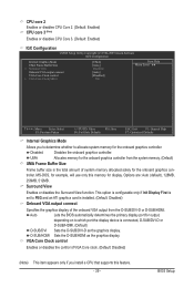
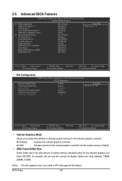
... or disables CPU Core 3. (Default: Enabled) IGX Configuration CMOS Setup Utility-Copyright (C) 1984-2009 Award Software IGX Configuration Internal Graphics Mode UMA Frame Buffer Size x Surround View Onboard VGA output connect VGA Core Clock control x VGA Core Clock(MHz) [UMA] [Auto] Disabled [Auto] [Disabled] 500 Item Help Menu Level Move Enter: Select F5: Previous Values +/-/PU/PD: Value F10: Save F6: Fail-Safe Defaults ESC: Exit F1: General Help F7: Optimized Defaults Internal Graphics Mode Allows you install a CPU that supports this memory...
... or disables CPU Core 3. (Default: Enabled) IGX Configuration CMOS Setup Utility-Copyright (C) 1984-2009 Award Software IGX Configuration Internal Graphics Mode UMA Frame Buffer Size x Surround View Onboard VGA output connect VGA Core Clock control x VGA Core Clock(MHz) [UMA] [Auto] Disabled [Auto] [Disabled] 500 Item Help Menu Level Move Enter: Select F5: Previous Values +/-/PU/PD: Value F10: Save F6: Fail-Safe Defaults ESC: Exit F1: General Help F7: Optimized Defaults Internal Graphics Mode Allows you install a CPU that supports this memory...
Manual
Page 40
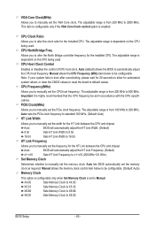
... CPU specifications. X5.33 Sets Memory Clock to alter the North Bridge controller frequency for automated system reboot, or clear the CMOS values to reset the board to automatically adjust the CPU host frequency. VGA Core Clock(MHz) Allows you to manually set to Manual. This item is configurable only if the VGA Core Clock control option is from 100 MHz to 16 bit. Allows you to X5.33. The adjustable range is set the VGA Core clock. Auto (default) allows the BIOS...
... CPU specifications. X5.33 Sets Memory Clock to alter the North Bridge controller frequency for automated system reboot, or clear the CMOS values to reset the board to automatically adjust the CPU host frequency. VGA Core Clock(MHz) Allows you to manually set to Manual. This item is configurable only if the VGA Core Clock control option is from 100 MHz to 16 bit. Allows you to X5.33. The adjustable range is set the VGA Core clock. Auto (default) allows the BIOS...
Manual
Page 46
... to HDD Init Display First [Press Enter] [Disabled] [Disabled] [Enabled] [Auto] [Press Enter] [Floppy] [Hard Disk] [CDROM] [Setup] [Disabled] [Disabled] [Disabled] [PCI Slot] Item Help Menu Level Move Enter: Select F5: Previous Values +/-/PU/PD: Value F10: Save F6: Fail-Safe Defaults ESC: Exit F1: General Help F7: Optimized Defaults IGX Configuration CMOS Setup Utility-Copyright (C) 1984-2009 Award Software IGX Configuration Internal Graphics Mode UMA Frame Buffer Size x Surround View Onboard VGA output connect VGA Core Clock control x VGA Core Clock...
... to HDD Init Display First [Press Enter] [Disabled] [Disabled] [Enabled] [Auto] [Press Enter] [Floppy] [Hard Disk] [CDROM] [Setup] [Disabled] [Disabled] [Disabled] [PCI Slot] Item Help Menu Level Move Enter: Select F5: Previous Values +/-/PU/PD: Value F10: Save F6: Fail-Safe Defaults ESC: Exit F1: General Help F7: Optimized Defaults IGX Configuration CMOS Setup Utility-Copyright (C) 1984-2009 Award Software IGX Configuration Internal Graphics Mode UMA Frame Buffer Size x Surround View Onboard VGA output connect VGA Core Clock control x VGA Core Clock...
Manual
Page 47
...&Quiet control Auto Lets the AMD Cool'n'Quiet driver dynamically adjust the CPU clock and VID to 2000 MHz. Use the up or down arrow key to select a device and press to accept. VGA Core Clock control Enables or disables the control of VGA Core clock. (Default: Disabled) VGA Core Clock(MHz) Allows you install a CPU that supports this feature. - 47 - Hard Disk Boot Priority Specifies the sequence of the onboard VGA output from the installed hard drives. BIOS Setup The adjustable range is installed. (Default: Disabled) Onboard VGA output connect Specifies the graphics display...
...&Quiet control Auto Lets the AMD Cool'n'Quiet driver dynamically adjust the CPU clock and VID to 2000 MHz. Use the up or down arrow key to select a device and press to accept. VGA Core Clock control Enables or disables the control of VGA Core clock. (Default: Disabled) VGA Core Clock(MHz) Allows you install a CPU that supports this feature. - 47 - Hard Disk Boot Priority Specifies the sequence of the onboard VGA output from the installed hard drives. BIOS Setup The adjustable range is installed. (Default: Disabled) Onboard VGA output connect Specifies the graphics display...
Manual
Page 48
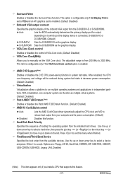
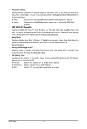
.../write errors of the monitor display from the installed PCI graphics card, PCI Express graphics card, or the onboard VGA. BIOS Setup - 48 - This feature allows your hard drive. If the system BIOS is required for booting the system and for entering the BIOS Setup program. (Default) System A password is corrupted, it will be recovered from this item, set the password(s) under the Set Supervisor/User Password item in the BIOS Main Menu. Password Check Specifies whether a password is installed. (Default: Enabled) Away Mode Enables or disables Away Mode in Windows XP...
.../write errors of the monitor display from the installed PCI graphics card, PCI Express graphics card, or the onboard VGA. BIOS Setup - 48 - This feature allows your hard drive. If the system BIOS is required for booting the system and for entering the BIOS Setup program. (Default) System A password is corrupted, it will be recovered from this item, set the password(s) under the Set Supervisor/User Password item in the BIOS Main Menu. Password Check Specifies whether a password is installed. (Default: Enabled) Away Mode Enables or disables Away Mode in Windows XP...
Manual
Page 49
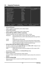
... Setup Utility-Copyright (C) 1984-2009 Award Software Integrated Peripherals OnChip IDE Channel OnChip SATA Controller OnChip SATA Type x OnChip SATA Port4/5 Type Onboard LAN Function Onboard LAN Boot ROM } SMART LAN Onboard Audio Function OnChip USB Controller USB EHCI Controller USB Keyboard Support USB Mouse Support Legacy USB storage detect Onboard Serial Port 1 Onboard Parallel Port Parallel Port Mode x ECP Mode Use DMA [Enabled] [Enabled] [Native IDE] IDE [Enabled] [Disabled] [Press Enter] [Enabled] [Enabled] [Enabled] [Enabled] [Disabled...
... Setup Utility-Copyright (C) 1984-2009 Award Software Integrated Peripherals OnChip IDE Channel OnChip SATA Controller OnChip SATA Type x OnChip SATA Port4/5 Type Onboard LAN Function Onboard LAN Boot ROM } SMART LAN Onboard Audio Function OnChip USB Controller USB EHCI Controller USB Keyboard Support USB Mouse Support Legacy USB storage detect Onboard Serial Port 1 Onboard Parallel Port Parallel Port Mode x ECP Mode Use DMA [Enabled] [Enabled] [Native IDE] IDE [Enabled] [Disabled] [Press Enter] [Enabled] [Enabled] [Enabled] [Enabled] [Disabled...
Manual
Page 51
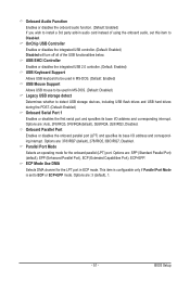
.... Options are : Auto, 2F8/IRQ3, 3F8/IRQ4(default), 3E8/IRQ4, 2E8/IRQ3, Disabled. This item is configurable only if Parallel Port Mode is set this item to Disabled. USB EHCI Controller Enables or disables the integrated USB 2.0 controller. (Default: Enabled) USB Keyboard Support Allows USB keyboard to be used in MS-DOS. (Default: Enabled) USB Mouse Support Allows USB mouse to be used in MS-DOS. (Default: Disabled) Legacy USB storage detect Determines whether to detect USB storage devices, including USB flash drives and USB hard drives during the POST. (Default: Enabled) Onboard Serial Port...
.... Options are : Auto, 2F8/IRQ3, 3F8/IRQ4(default), 3E8/IRQ4, 2E8/IRQ3, Disabled. This item is configurable only if Parallel Port Mode is set this item to Disabled. USB EHCI Controller Enables or disables the integrated USB 2.0 controller. (Default: Enabled) USB Keyboard Support Allows USB keyboard to be used in MS-DOS. (Default: Enabled) USB Mouse Support Allows USB mouse to be used in MS-DOS. (Default: Disabled) Legacy USB storage detect Determines whether to detect USB storage devices, including USB flash drives and USB hard drives during the POST. (Default: Enabled) Onboard Serial Port...
Manual
Page 52
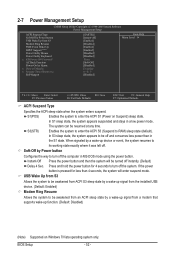
... computer in a low power mode. 2-7 Power Management Setup CMOS Setup Utility-Copyright (C) 1984-2009 Award Software Power Management Setup ACPI Suspend Type Soft-Off by Power button USB Wake Up from a modem that supports wake-up function. (Default: Disabled) (Note) Supported on Suspend) sleep state. Instant-Off Press the power button and then the system will enter suspend mode. S3(STR) Enables the system to enter the ACPI S3 (Suspend to enter the ACPI S1 (Power on Windows 7/Vista operating system only. BIOS Setup - 52 - When...
... computer in a low power mode. 2-7 Power Management Setup CMOS Setup Utility-Copyright (C) 1984-2009 Award Software Power Management Setup ACPI Suspend Type Soft-Off by Power button USB Wake Up from a modem that supports wake-up function. (Default: Disabled) (Note) Supported on Suspend) sleep state. Instant-Off Press the power button and then the system will enter suspend mode. S3(STR) Enables the system to enter the ACPI S3 (Suspend to enter the ACPI S1 (Power on Windows 7/Vista operating system only. BIOS Setup - 52 - When...
Manual
Page 68
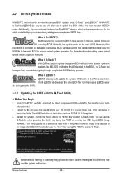
... the BIOS file to the main BIOS to an independent IDE/SATA controller, use FAT32/16/12 file system. 3. Inadequate BIOS flashing may result in RAID/AHCI mode or a hard drive attached to ensure normal system operation. 4-2 BIOS Update Utilities GIGABYTE motherboards provide two unique BIOS update tools, Q-Flash™ and @BIOS™. Motherboards that matches your floppy disk, USB flash drive, or hard drive. For the sake of going through complicated BIOS flashing process. Embedded in BIOS Setup. Before You Begin 1. Note: The USB flash drive or hard drive must use the key...
... the BIOS file to the main BIOS to an independent IDE/SATA controller, use FAT32/16/12 file system. 3. Inadequate BIOS flashing may result in RAID/AHCI mode or a hard drive attached to ensure normal system operation. 4-2 BIOS Update Utilities GIGABYTE motherboards provide two unique BIOS update tools, Q-Flash™ and @BIOS™. Motherboards that matches your floppy disk, USB flash drive, or hard drive. For the sake of going through complicated BIOS flashing process. Embedded in BIOS Setup. Before You Begin 1. Note: The USB flash drive or hard drive must use the key...
Manual
Page 77
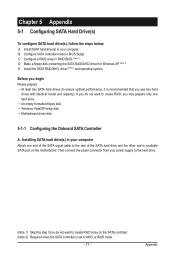
...set to create RAID array on the motherboard. Appendix B. C. Install SATA hard drive(s) in RAID BIOS. (Note 1) D. Then connect the power connector from your power supply to the hard drive. (Note 1) Skip this step if you do not want to AHCI or RAID mode. - 77 - Install the SATA RAID/AHCI driver (Note 2) and operating system. Installing SATA hard drive(s) in BIOS Setup. Configure a RAID array in your computer Attach one hard drive. • An empty formatted floppy disk. • Windows Vista/XP setup disk. • Motherboard driver disk. 5-1-1 Configuring the Onboard SATA...
...set to create RAID array on the motherboard. Appendix B. C. Install SATA hard drive(s) in RAID BIOS. (Note 1) D. Then connect the power connector from your power supply to the hard drive. (Note 1) Skip this step if you do not want to AHCI or RAID mode. - 77 - Install the SATA RAID/AHCI driver (Note 2) and operating system. Installing SATA hard drive(s) in BIOS Setup. Configure a RAID array in your computer Attach one hard drive. • An empty formatted floppy disk. • Windows Vista/XP setup disk. • Motherboard driver disk. 5-1-1 Configuring the Onboard SATA...
Manual
Page 83
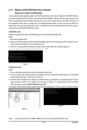
... Windows mode: Steps: 1: Use an alternative system and insert the motherboard driver disk. 2: From your optical drive is /are configured to RAID/AHCI mode, you need to a floppy disk. In MS-DOS mode: Prepare a startup disk that has CD-ROM support and a blank formatted floppy disk. Press any key to the floppy disk. Figure 2 Figure 3 (Note) Change the directory from \x86 to \x64 if you also can copy the SATA controller driver from the motherboard driver disk to install the SATA controller driver...
... Windows mode: Steps: 1: Use an alternative system and insert the motherboard driver disk. 2: From your optical drive is /are configured to RAID/AHCI mode, you need to a floppy disk. In MS-DOS mode: Prepare a startup disk that has CD-ROM support and a blank formatted floppy disk. Press any key to the floppy disk. Figure 2 Figure 3 (Note) Change the directory from \x86 to \x64 if you also can copy the SATA controller driver from the motherboard driver disk to install the SATA controller driver...
Manual
Page 84
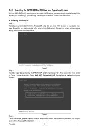
... driver. AMD AHCI Compatible RAID Controller-x86 platform AMD AHCI Compatible RAID Controller-x64 platform ENTER=Select F3=Exit Step 3: Figure 2 On the next screen, press to configure a SCSI Adapter for use with the Windows XP installation. ceed with Windows, using a device support disk provided by an adapter manufacturer. Installing Windows XP Step 1: Restart your hard drive(s). Select the SCSI Adapter you need to specify additional device. 5-1-3 Installing the SATA RAID/AHCI Driver and Operating System With the SATA RAID/AHCI driver diskette and correct BIOS settings...
... driver. AMD AHCI Compatible RAID Controller-x86 platform AMD AHCI Compatible RAID Controller-x64 platform ENTER=Select F3=Exit Step 3: Figure 2 On the next screen, press to configure a SCSI Adapter for use with the Windows XP installation. ceed with Windows, using a device support disk provided by an adapter manufacturer. Installing Windows XP Step 1: Restart your hard drive(s). Select the SCSI Adapter you need to specify additional device. 5-1-3 Installing the SATA RAID/AHCI Driver and Operating System With the SATA RAID/AHCI driver diskette and correct BIOS settings...
Manual
Page 95
... A: The following Award BIOS beep code descriptions may help you identify possible computer problems. (For reference only.) 1 short: System boots successfully 1 long, 3 short: Keyboard error 2 short: CMOS setting error 1 long, 9 short: BIOS ROM error 1 long, 1 short: Memory or motherboard error Continuous long beeps: Graphics card not inserted properly 1 long, 2 short: Monitor or graphics card error Continuous short beeps: Power error - 95 - Q: Why is equipped with power/amplifier. Q: Why cannot I install the onboard HD audio driver successfully? (For Windows XP only) A: Step...
... A: The following Award BIOS beep code descriptions may help you identify possible computer problems. (For reference only.) 1 short: System boots successfully 1 long, 3 short: Keyboard error 2 short: CMOS setting error 1 long, 9 short: BIOS ROM error 1 long, 1 short: Memory or motherboard error Continuous long beeps: Graphics card not inserted properly 1 long, 2 short: Monitor or graphics card error Continuous short beeps: Power error - 95 - Q: Why is equipped with power/amplifier. Q: Why cannot I install the onboard HD audio driver successfully? (For Windows XP only) A: Step...


