Manual
Page 1
GA-MA78LMT-S2H/ GA-MA78LMT-S2 AM3 socket motherboard for AMD Phenom™ II processor/ AMD Athlon™ II processor User's Manual Rev. 1001 12ME-MA78LT2-1001R
GA-MA78LMT-S2H/ GA-MA78LMT-S2 AM3 socket motherboard for AMD Phenom™ II processor/ AMD Athlon™ II processor User's Manual Rev. 1001 12ME-MA78LT2-1001R
Manual
Page 2
Motherboard GA-MA78LMT-S2H/GA-MA78LMT-S2 Nov. 27, 2009 Motherboard GA-MA78LMT-S2H/ GA-MA78LMT-S2 Nov. 27, 2009
Motherboard GA-MA78LMT-S2H/GA-MA78LMT-S2 Nov. 27, 2009 Motherboard GA-MA78LMT-S2H/ GA-MA78LMT-S2 Nov. 27, 2009
Manual
Page 3
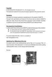
...the revision of this manual may be made by GIGABYTE without GIGABYTE's prior written permission. For product-related information, check on our website at: http://www.gigabyte.com.tw Identifying Your Motherboard Revision The revision number on our website. Disclaimer ...: "REV: X.X." Documentation Classifications In order to use GIGABYTE's unique features, read or download the information on/from the Support&Downloads\Motherboard\Technology Guide page on your motherboard revision before updating motherboard BIOS, drivers, or when looking for technical information. All...
...the revision of this manual may be made by GIGABYTE without GIGABYTE's prior written permission. For product-related information, check on our website at: http://www.gigabyte.com.tw Identifying Your Motherboard Revision The revision number on our website. Disclaimer ...: "REV: X.X." Documentation Classifications In order to use GIGABYTE's unique features, read or download the information on/from the Support&Downloads\Motherboard\Technology Guide page on your motherboard revision before updating motherboard BIOS, drivers, or when looking for technical information. All...
Manual
Page 4
Table of Contents Box Contents...6 Optional Items...6 GA-MA78LMT-S2H/GA-MA78LMT-S2 Motherboard Layout 7 Block Diagram...8 Chapter 1 Hardware Installation 9 1-1 Installation Precautions 9 1-2 Product Specifications 10 1-3 Installing the CPU and CPU Cooler 13 1-3-1 Installing the CPU 13 1-3-2 Installing the CPU ...
Table of Contents Box Contents...6 Optional Items...6 GA-MA78LMT-S2H/GA-MA78LMT-S2 Motherboard Layout 7 Block Diagram...8 Chapter 1 Hardware Installation 9 1-1 Installation Precautions 9 1-2 Product Specifications 10 1-3 Installing the CPU and CPU Cooler 13 1-3-1 Installing the CPU 13 1-3-2 Installing the CPU ...
Manual
Page 6
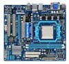
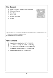
The box contents are for reference only. Box Contents GA-MA78LMT-S2H or GA-MA78LMT-S2 motherboard Motherboard driver disk User's Manual One IDE cable Two SATA 3Gb/s cables I/O Shield • The box contents above are subject to change without notice. • The motherboard image is for reference only and the actual items shall depend on the product package...
The box contents are for reference only. Box Contents GA-MA78LMT-S2H or GA-MA78LMT-S2 motherboard Motherboard driver disk User's Manual One IDE cable Two SATA 3Gb/s cables I/O Shield • The box contents above are subject to change without notice. • The motherboard image is for reference only and the actual items shall depend on the product package...
Manual
Page 7
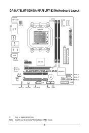
GA-MA78LMT-S2H/GA-MA78LMT-S2 Motherboard Layout KB(Note)_USB ATX_12V CPU_FAN Socket AM3 M_BIOS B_BIOS ATX IT8718 VGA DVI HDMIj R_USB USB IDE FDD LAN AUDIO F_AUDIO PCIEX1 AMD 760G DDR3_1 DDR3_2 PCIEX16 RTL8111D PCI1 GA-MA78LMT-S2H/GA-MA78LMT-S2 AMD SB710 CD_IN CODEC PCI2 BAT SATA2_0 COM SATA2_3 SATA2_2 SATA2_1 F_PANEL SPDIF_IO SYS_FAN CLR_CMOS F_USB2 F_USB1 j Only for GA-MA78LMT-S2H (Note) Use this port to connect a PS/2 keyboard or PS/2 mouse. - 7 -
GA-MA78LMT-S2H/GA-MA78LMT-S2 Motherboard Layout KB(Note)_USB ATX_12V CPU_FAN Socket AM3 M_BIOS B_BIOS ATX IT8718 VGA DVI HDMIj R_USB USB IDE FDD LAN AUDIO F_AUDIO PCIEX1 AMD 760G DDR3_1 DDR3_2 PCIEX16 RTL8111D PCI1 GA-MA78LMT-S2H/GA-MA78LMT-S2 AMD SB710 CD_IN CODEC PCI2 BAT SATA2_0 COM SATA2_3 SATA2_2 SATA2_1 F_PANEL SPDIF_IO SYS_FAN CLR_CMOS F_USB2 F_USB1 j Only for GA-MA78LMT-S2H (Note) Use this port to connect a PS/2 keyboard or PS/2 mouse. - 7 -
Manual
Page 9
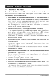
...wear an electrostatic discharge (ESD) wrist strap when handling electronic com- If you are connected tightly and securely. • When handling the motherboard, avoid touching any installation steps or have a problem related to installation, do not have an ESD wrist strap, keep your dealer. ...-temperature environment. • Turning on the computer power during the installation process can lead to damage to system components as well as a motherboard, CPU or memory. Prior to installation, carefully read the user's manual and follow these procedures: • Prior to the use of the...
...wear an electrostatic discharge (ESD) wrist strap when handling electronic com- If you are connected tightly and securely. • When handling the motherboard, avoid touching any installation steps or have a problem related to installation, do not have an ESD wrist strap, keep your dealer. ...-temperature environment. • Turning on the computer power during the installation process can lead to damage to system components as well as a motherboard, CPU or memory. Prior to installation, carefully read the user's manual and follow these procedures: • Prior to the use of the...
Manual
Page 12
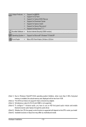
... 5) Whether the CPU fan speed control function is supported will depend on the CPU cooler you install. (Note 6) Available functions in EasyTune may differ by motherboard model.
... 5) Whether the CPU fan speed control function is supported will depend on the CPU cooler you install. (Note 6) Available functions in EasyTune may differ by motherboard model.
Manual
Page 13
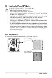
... AM3 CPU - 13 - If you may occur. • Set the CPU host frequency in accordance with the CPU specifications. It is not recommended that the motherboard supports the CPU. (Go to GIGABYTE's website for the peripherals.
... AM3 CPU - 13 - If you may occur. • Set the CPU host frequency in accordance with the CPU specifications. It is not recommended that the motherboard supports the CPU. (Go to GIGABYTE's website for the peripherals.
Manual
Page 14
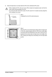
... incorrectly. CPU Socket Locking Lever Step 1: Completely lift up the CPU socket locking lever. Follow the steps below to correctly install the CPU into the motherboard CPU socket. • Before installing the CPU, make sure to turn off the computer and unplug the power cord from the power outlet to prevent...
... incorrectly. CPU Socket Locking Lever Step 1: Completely lift up the CPU socket locking lever. Follow the steps below to correctly install the CPU into the motherboard CPU socket. • Before installing the CPU, make sure to turn off the computer and unplug the power cord from the power outlet to prevent...
Manual
Page 15
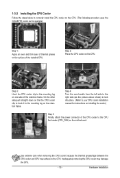
... Hardware Installation 1-3-2 Installing the CPU Cooler Follow the steps below to correctly install the CPU cooler on the CPU. (The following procedure uses the GIGABYTE cooler as the picture above shows) to lock into place. (Refer to your CPU cooler installation manual for instructions on installing the cooler.) Step 5:... Finally, attach the power connector of the CPU cooler to the CPU fan header (CPU_FAN) on the motherboard. Step 3: Hook the CPU cooler clip to the CPU. Step 4: Turn the cam handle from the left side to the mounting lug on...
... Hardware Installation 1-3-2 Installing the CPU Cooler Follow the steps below to correctly install the CPU cooler on the CPU. (The following procedure uses the GIGABYTE cooler as the picture above shows) to lock into place. (Refer to your CPU cooler installation manual for instructions on installing the cooler.) Step 5:... Finally, attach the power connector of the CPU cooler to the CPU fan header (CPU_FAN) on the motherboard. Step 3: Hook the CPU cooler clip to the CPU. Step 4: Turn the cam handle from the left side to the mounting lug on...
Manual
Page 16
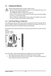
...that memory of the memory. It is recommended that memory of the same capacity, brand, speed, and chips be used . (Go to GIGABYTE's website for the latest memory support list.) • Always turn off the computer and unplug the power cord from the power outlet before installing... the memory to install the memory: • Make sure that the motherboard supports the memory. Hardware Installation - 16 - 1-4 Installing the Memory Read the following guidelines before installing the memory in only one direction. The...
...that memory of the memory. It is recommended that memory of the same capacity, brand, speed, and chips be used . (Go to GIGABYTE's website for the latest memory support list.) • Always turn off the computer and unplug the power cord from the power outlet before installing... the memory to install the memory: • Make sure that the motherboard supports the memory. Hardware Installation - 16 - 1-4 Installing the Memory Read the following guidelines before installing the memory in only one direction. The...
Manual
Page 17
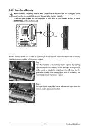
..., make sure to turn off the computer and unplug the power cord from the power outlet to prevent damage to install DDR3 DIMMs on this motherboard. As indicated in the picture on the socket. Hardware Installation Step 1: Note the orientation of the memory socket. Place the memory module on the left...
..., make sure to turn off the computer and unplug the power cord from the power outlet to prevent damage to install DDR3 DIMMs on this motherboard. As indicated in the picture on the socket. Hardware Installation Step 1: Note the orientation of the memory socket. Place the memory module on the left...
Manual
Page 18
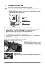
.... Install the driver provided with the expansion card in your computer. Secure the card's metal bracket to install an expansion card: • Make sure the motherboard supports the expansion card. Example: Installing and Removing a PCI Express Graphics Card: • Installing a Graphics Card: Gently push down on the slot and then lift...
.... Install the driver provided with the expansion card in your computer. Secure the card's metal bracket to install an expansion card: • Make sure the motherboard supports the expansion card. Example: Installing and Removing a PCI Express Graphics Card: • Installing a Graphics Card: Gently push down on the slot and then lift...
Manual
Page 20
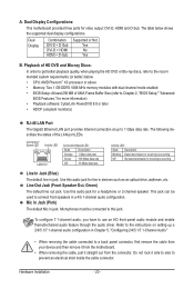
... • When removing the cable connected to a back panel connector, first remove the cable from your device and then remove it from the motherboard. • When removing the cable, pull it side to side to Chapter 2, "BIOS Setup," "Advanced BIOS Features," for video output: ... inside the cable connector. Hardware Installation - 20 - Mic In Jack (Pink) The default Mic in jack. A. Dual Display Configurations: This motherboard provides three ports for more information) • Playback software: CyberLink PowerDVD 8.0 or later • HDCP compliant monitor(s) RJ-45 LAN Port...
... • When removing the cable connected to a back panel connector, first remove the cable from your device and then remove it from the motherboard. • When removing the cable, pull it side to side to Chapter 2, "BIOS Setup," "Advanced BIOS Features," for video output: ... inside the cable connector. Hardware Installation - 20 - Mic In Jack (Pink) The default Mic in jack. A. Dual Display Configurations: This motherboard provides three ports for more information) • Playback software: CyberLink PowerDVD 8.0 or later • HDCP compliant monitor(s) RJ-45 LAN Port...
Manual
Page 21
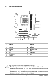
..., make sure your devices are compliant with the connectors you wish to connect. • Before installing the devices, be sure to the connector on the motherboard. - 21 - Hardware Installation
..., make sure your devices are compliant with the connectors you wish to connect. • Before installing the devices, be sure to the connector on the motherboard. - 21 - Hardware Installation
Manual
Page 22
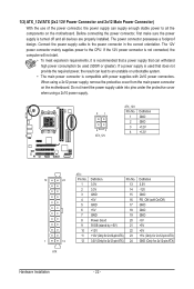
... power supply cable into pins under the protective cover when using a 2x12 power supply, remove the protective cover from the main power connector on the motherboard. If the 12V power connector is not connected, the computer will not start. • To meet expansion requirements, it is turned off and all the...
... power supply cable into pins under the protective cover when using a 2x12 power supply, remove the protective cover from the main power connector on the motherboard. If the 12V power connector is not connected, the computer will not start. • To meet expansion requirements, it is turned off and all the...
Manual
Page 23
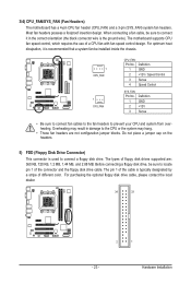
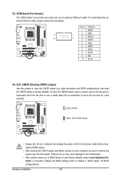
...). For purchasing the optional floppy disk drive cable, please contact the local dealer. 34 33 2 1 - 23 - The motherboard supports CPU fan speed control, which requires the use of different color. 3/4) CPU_FAN/SYS_FAN (Fan Headers) The motherboard has a 4-pin CPU fan header (CPU_FAN) and a 3-pin (SYS_FAN) system fan headers. The types of the...
...). For purchasing the optional floppy disk drive cable, please contact the local dealer. 34 33 2 1 - 23 - The motherboard supports CPU fan speed control, which requires the use of different color. 3/4) CPU_FAN/SYS_FAN (Fan Headers) The motherboard has a 4-pin CPU fan header (CPU_FAN) and a 3-pin (SYS_FAN) system fan headers. The types of the...
Manual
Page 26
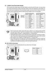
... Audio Header) The front panel audio header supports Intel High Definition audio (HD) and AC'97 audio. Incorrect connection between the module connector and the motherboard header will be present on each wire instead of the...
... Audio Header) The front panel audio header supports Intel High Definition audio (HD) and AC'97 audio. Incorrect connection between the module connector and the motherboard header will be present on each wire instead of the...
Manual
Page 28
... Values • Always turn off your computer, be sure to Chapter 2, "BIOS Setup," for a few seconds. Failure to do so may cause damage to the motherboard. • After system restart, go to BIOS Setup to load factory defaults (select Load Optimized Defaults) or manually configure the BIOS settings (refer to remove...
... Values • Always turn off your computer, be sure to Chapter 2, "BIOS Setup," for a few seconds. Failure to do so may cause damage to the motherboard. • After system restart, go to BIOS Setup to load factory defaults (select Load Optimized Defaults) or manually configure the BIOS settings (refer to remove...


