Manual
Page 1
GA-M720-ES3 AM2+/AM2 socket motherboard for AMD PhenomTM II processor/AMD PhenomTM processor/ AMD AthlonTM II processor/AMD AthlonTM processor/ AMD SempronTM processor User's Manual Rev. 1001 12ME-M720ES3-1001R
GA-M720-ES3 AM2+/AM2 socket motherboard for AMD PhenomTM II processor/AMD PhenomTM processor/ AMD AthlonTM II processor/AMD AthlonTM processor/ AMD SempronTM processor User's Manual Rev. 1001 12ME-M720ES3-1001R

Manual
Page 2
Motherboard GA-M720-ES3 June 25, 2009 Motherboard GA-M720-ES3 June 25, 2009
Motherboard GA-M720-ES3 June 25, 2009 Motherboard GA-M720-ES3 June 25, 2009

Manual
Page 3
...your motherboard revision before updating motherboard BIOS, drivers, or when looking for technical information. Check your motherboard looks like this product, GIGABYTE provides the following types of documentations: For quick set-up of the product, read the Quick Installation Guide included with ..."REV: 1.0" means the revision of the motherboard is the property of this manual may be made by any form or by GIGABYTE without GIGABYTE's prior written permission. Copyright © 2009 GIGA-BYTE TECHNOLOGY CO., LTD. Disclaimer Information in this manual are legally registered to...
...your motherboard revision before updating motherboard BIOS, drivers, or when looking for technical information. Check your motherboard looks like this product, GIGABYTE provides the following types of documentations: For quick set-up of the product, read the Quick Installation Guide included with ..."REV: 1.0" means the revision of the motherboard is the property of this manual may be made by any form or by GIGABYTE without GIGABYTE's prior written permission. Copyright © 2009 GIGA-BYTE TECHNOLOGY CO., LTD. Disclaimer Information in this manual are legally registered to...
Manual
Page 4
Table of Contents Box Contents ...6 OptionalItems...6 GA-M720-ES3 Motherboard Layout 7 Block Diagram...8 Chapter 1 Hardware Installation 9 1-1 Installation Precautions 9 1-2 Product Specifications 10 1-3 Installing the CPU and CPU Cooler 12 1-3-1 Installing the CPU 12 1-3-2 Installing the ...
Table of Contents Box Contents ...6 OptionalItems...6 GA-M720-ES3 Motherboard Layout 7 Block Diagram...8 Chapter 1 Hardware Installation 9 1-1 Installation Precautions 9 1-2 Product Specifications 10 1-3 Installing the CPU and CPU Cooler 12 1-3-1 Installing the CPU 12 1-3-2 Installing the ...

Manual
Page 5
Chapter 3 Drivers Installation 55 3-1 Installing Chipset Drivers 55 3-2 Software Applications 56 3-3 Driver CD Information 56 3-4 Hardware Information 57 3-5 Contact Us ...57 Chapter 4 Unique Features 59 4-1 Xpress Recovery2 59 4-2 BIOS Update Utilities 62 4-2-1 Updating the BIOS with the Q-Flash Utility 62 4-2-2 Updating the BIOS with the @BIOS Utility 65 4-3 EasyTune 6 ...66 4-4 Easy Energy Saver 67 Chapter 5 Appendix ...69 5-1 Configuring SATA Hard Drive(s 69 5-1-1 Configuring the Onboard SATA Controller 69 5-1-2 Making a SATA RAID/AHCI Driver Diskette for Windows XP 74 5-1-3 ...
Chapter 3 Drivers Installation 55 3-1 Installing Chipset Drivers 55 3-2 Software Applications 56 3-3 Driver CD Information 56 3-4 Hardware Information 57 3-5 Contact Us ...57 Chapter 4 Unique Features 59 4-1 Xpress Recovery2 59 4-2 BIOS Update Utilities 62 4-2-1 Updating the BIOS with the Q-Flash Utility 62 4-2-2 Updating the BIOS with the @BIOS Utility 65 4-3 EasyTune 6 ...66 4-4 Easy Energy Saver 67 Chapter 5 Appendix ...69 5-1 Configuring SATA Hard Drive(s 69 5-1-1 Configuring the Onboard SATA Controller 69 5-1-2 Making a SATA RAID/AHCI Driver Diskette for Windows XP 74 5-1-3 ...

Manual
Page 6
The box contents are for reference only. Box Contents GA-M720-ES3 motherboard Motherboard driver disk User's Manual Quick Installation Guide One IDE cable Two SATA 3Gb/s cables I/O Shield • The box contents above are subject to ...
The box contents are for reference only. Box Contents GA-M720-ES3 motherboard Motherboard driver disk User's Manual Quick Installation Guide One IDE cable Two SATA 3Gb/s cables I/O Shield • The box contents above are subject to ...

Manual
Page 7
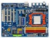
GA-M720-ES3 Motherboard Layout KB_MS RCA_SPDIF R_USB R_USB R_USB USB_LAN ATX_12V Socket AM2 PWR_FAN F_AUDIO AUDIO CPU_FAN PCIEX1_1 RTL8111C PCIEX1_2 PCIEX16 CODEC PCI1 PCI2 NVIDIA® nForce 720D GA-M720-ES3 SATA2_2 SATA2_1 SATA2_0 SATA2_5 SATA2_4 SATA2_3 BATTERY DDR2_1 DDR2_2 DDR2_3 DDR2_4 ATX IDE CD_IN SPDIF_O SYS_FAN1 PCI3 IT8720 PCI4 M_BIOS B_BIOS COM FDD TSB43AB23 SYS_FAN2 CI F_PANEL F_USB1 PWR_LED F_USB2 CLR_CMOS - 7 -
GA-M720-ES3 Motherboard Layout KB_MS RCA_SPDIF R_USB R_USB R_USB USB_LAN ATX_12V Socket AM2 PWR_FAN F_AUDIO AUDIO CPU_FAN PCIEX1_1 RTL8111C PCIEX1_2 PCIEX16 CODEC PCI1 PCI2 NVIDIA® nForce 720D GA-M720-ES3 SATA2_2 SATA2_1 SATA2_0 SATA2_5 SATA2_4 SATA2_3 BATTERY DDR2_1 DDR2_2 DDR2_3 DDR2_4 ATX IDE CD_IN SPDIF_O SYS_FAN1 PCI3 IT8720 PCI4 M_BIOS B_BIOS COM FDD TSB43AB23 SYS_FAN2 CI F_PANEL F_USB1 PWR_LED F_USB2 CLR_CMOS - 7 -

Manual
Page 8
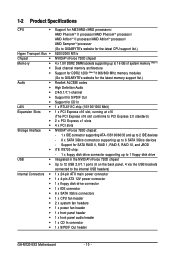
Block Diagram PCIe CLK (100 MHz) 1 PCI Express x16 PCI Express x16 AM3/AM2+/AM2 CPU CPU CLK+/-(200 MHz) DDR2 1200 (Note)/1066/800 MHz Hyper Transport 3.0 Dual Channel Memory PCI Express x1 Bus x1 PCIe CLK (100 MHz) x1 RTL8111C RJ45 2 PCI Express x1 LAN NVIDIA® nForce 720D 12 USB Ports 6 SATA 3Gb/s ATA-133/100/66/33 IDE Channel PCI Bus 4 PCI CODEC LPC BUS IT8720 Dual BIOS Floppy COM Port PS/2 KB/Mouse Surround Speaker Out Center/Subwoofer Speaker Out Side Speaker Out MIC Line Out Line In S/PDIF Out PCI CLK (33 MHz) (Note) Whether 1200 MHz memory speed is supported depends ...
Block Diagram PCIe CLK (100 MHz) 1 PCI Express x16 PCI Express x16 AM3/AM2+/AM2 CPU CPU CLK+/-(200 MHz) DDR2 1200 (Note)/1066/800 MHz Hyper Transport 3.0 Dual Channel Memory PCI Express x1 Bus x1 PCIe CLK (100 MHz) x1 RTL8111C RJ45 2 PCI Express x1 LAN NVIDIA® nForce 720D 12 USB Ports 6 SATA 3Gb/s ATA-133/100/66/33 IDE Channel PCI Bus 4 PCI CODEC LPC BUS IT8720 Dual BIOS Floppy COM Port PS/2 KB/Mouse Surround Speaker Out Center/Subwoofer Speaker Out Side Speaker Out MIC Line Out Line In S/PDIF Out PCI CLK (33 MHz) (Note) Whether 1200 MHz memory speed is supported depends ...

Manual
Page 9
Hardware Installation These stickers are required for warranty validation. • Always remove the AC power by your dealer. Prior to installation, carefully read the user's manual and follow these procedures: • Prior to installation, do not remove or break motherboard S/N (Serial Number) sticker or warranty sticker provided by unplugging the power cord from the motherboard, make sure the power supply has been turned off. • Before turning on the computer power during the installation process can become damaged as a motherboard, CPU or memory. Chapter 1 Hardware ...
Hardware Installation These stickers are required for warranty validation. • Always remove the AC power by your dealer. Prior to installation, carefully read the user's manual and follow these procedures: • Prior to installation, do not remove or break motherboard S/N (Serial Number) sticker or warranty sticker provided by unplugging the power cord from the motherboard, make sure the power supply has been turned off. • Before turning on the computer power during the installation process can become damaged as a motherboard, CPU or memory. Chapter 1 Hardware ...
Manual
Page 10
...II processor/AMD PhenomTM processor/ AMD AthlonTM II processor/AMD AthlonTM processor/ AMD SempronTM processor (Go to GIGABYTE's website for the latest CPU support list.) 5200/2000 MT/s NVIDIA® nForce 720D chipset 4 ...Note 1) Dual channel memory architecture Support for DDR2 1200 (Note 2)/1066/800 MHz memory modules (Go to GIGABYTE's website for the latest memory support list.) Realtek ALC888 codec High Definition Audio 2/4/5.1/7.1-channel Support for S/PDIF... header 1 x front panel header 1 x front panel audio header 1 x CD In connector 1 x S/PDIF Out header GA-M720-ES3 Motherboard - 10 -
...II processor/AMD PhenomTM processor/ AMD AthlonTM II processor/AMD AthlonTM processor/ AMD SempronTM processor (Go to GIGABYTE's website for the latest CPU support list.) 5200/2000 MT/s NVIDIA® nForce 720D chipset 4 ...Note 1) Dual channel memory architecture Support for DDR2 1200 (Note 2)/1066/800 MHz memory modules (Go to GIGABYTE's website for the latest memory support list.) Realtek ALC888 codec High Definition Audio 2/4/5.1/7.1-channel Support for S/PDIF... header 1 x front panel header 1 x front panel audio header 1 x CD In connector 1 x S/PDIF Out header GA-M720-ES3 Motherboard - 10 -

Manual
Page 11
Hardware Installation Internal Connectors 2 x USB 2.0/1.1 headers 1 x serial port header 1 x power LED header 1 x chassis intrusion header 1 x clearing CMOS switch Back Panel 1 x PS/2 keyboard port Connectors 1 x PS/2 mouse port 1 x coaxial S/PDIF Out connector 1 x optical S/PDIF Out connector 8 x USB 2.0/1.1 ports 1 x RJ-45 port 6 x audio jacks (Center/Subwoofer Speaker Out/Rear Speaker Out/Side Speaker Out/Line In/Line Out/Microphone) I/O Controller iTE ...
Hardware Installation Internal Connectors 2 x USB 2.0/1.1 headers 1 x serial port header 1 x power LED header 1 x chassis intrusion header 1 x clearing CMOS switch Back Panel 1 x PS/2 keyboard port Connectors 1 x PS/2 mouse port 1 x coaxial S/PDIF Out connector 1 x optical S/PDIF Out connector 8 x USB 2.0/1.1 ports 1 x RJ-45 port 6 x audio jacks (Center/Subwoofer Speaker Out/Rear Speaker Out/Side Speaker Out/Line In/Line Out/Microphone) I/O Controller iTE ...
Manual
Page 12
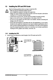
mended that the motherboard supports the CPU. (Go to GIGABYTE's website for the peripherals. Locate the pin one of the CPU may occur. • Set the CPU host frequency in accordance with the CPU specifications. .... • Locate the pin one (denoted by a small triangle) of the Socket AM2 Socket A Small Triangle Marking Denotes CPU Pin One AM3/AM2+/AM2 CPU GA-M720-ES3 Motherboard - 12 - It is not installed, otherwise overheating and damage of the CPU. A Small Triangle Mark Denotes Pin One of the CPU socket and the...
mended that the motherboard supports the CPU. (Go to GIGABYTE's website for the peripherals. Locate the pin one of the CPU may occur. • Set the CPU host frequency in accordance with the CPU specifications. .... • Locate the pin one (denoted by a small triangle) of the Socket AM2 Socket A Small Triangle Marking Denotes CPU Pin One AM3/AM2+/AM2 CPU GA-M720-ES3 Motherboard - 12 - It is not installed, otherwise overheating and damage of the CPU. A Small Triangle Mark Denotes Pin One of the CPU socket and the...

Manual
Page 13
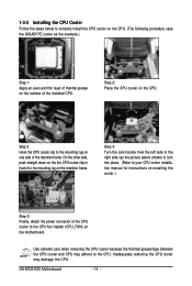
Make sure that the CPU pins fit perfectly into the CPU socket. Before installing the CPU, make sure to turn off the computer and unplug the power cord from the power outlet to prevent damage to correctly install the CPU into the motherboard CPU socket. Hardware Installation Follow the steps below to the CPU. Step 2: Align the CPU pin one finger down on the CPU socket and gently insert the CPU into the fully locked position. B. Do not force the CPU into their holes. Adjust the CPU orientation if this occurs. - 13 - Once the CPU is positioned into its socket, place one (...
Make sure that the CPU pins fit perfectly into the CPU socket. Before installing the CPU, make sure to turn off the computer and unplug the power cord from the power outlet to prevent damage to correctly install the CPU into the motherboard CPU socket. Hardware Installation Follow the steps below to the CPU. Step 2: Align the CPU pin one finger down on the CPU socket and gently insert the CPU into the fully locked position. B. Do not force the CPU into their holes. Adjust the CPU orientation if this occurs. - 13 - Once the CPU is positioned into its socket, place one (...
Manual
Page 14
... the steps below to the CPU. GA-M720-ES3 Motherboard - 14 - Step 3: Hook the CPU cooler clip to the mounting lug on the retention frame. Inadequately removing the CPU cooler may adhere to correctly install the CPU cooler on the CPU. (The following procedure uses the GIGABYTE cooler as the picture above shows) to...
... the steps below to the CPU. GA-M720-ES3 Motherboard - 14 - Step 3: Hook the CPU cooler clip to the mounting lug on the retention frame. Inadequately removing the CPU cooler may adhere to correctly install the CPU cooler on the CPU. (The following procedure uses the GIGABYTE cooler as the picture above shows) to...

Manual
Page 15
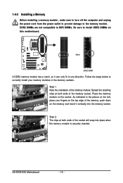
... recommended that you begin to install the memory: • Make sure that memory of the same capacity, brand, speed, and chips be used . (Go to GIGABYTE's website for optimum performance. - 15 - DDR2_1 DDR2_2 DDR2_3 DDR2_4 Due to CPU limitation, read the following guidelines before installing the memory in the same colored...
... recommended that you begin to install the memory: • Make sure that memory of the same capacity, brand, speed, and chips be used . (Go to GIGABYTE's website for optimum performance. - 15 - DDR2_1 DDR2_2 DDR2_3 DDR2_4 Due to CPU limitation, read the following guidelines before installing the memory in the same colored...
Manual
Page 16
... on the top edge of the memory module. DDR2 DIMMs are not compatible to DDR DIMMs. Be sure to install DDR2 DIMMs on the socket. GA-M720-ES3 Motherboard - 16 - As indicated in the picture on the left, place your memory modules in one direction. Follow the steps below to the memory module...
... on the top edge of the memory module. DDR2 DIMMs are not compatible to DDR DIMMs. Be sure to install DDR2 DIMMs on the socket. GA-M720-ES3 Motherboard - 16 - As indicated in the picture on the left, place your memory modules in one direction. Follow the steps below to the memory module...

Manual
Page 17
Align the card with your operating system. Turn on the card are completely inserted into the PCIEX16 slot. Make sure the card is securely seated in the slot. 3. Carefully read the manual that supports your expansion card in your expansion card. • Always turn off the computer and unplug the power cord from the power outlet before you begin to install an expansion card: • Make sure the motherboard supports the expansion card. Install the driver provided with a screw. 5. Secure the card's metal bracket to the chassis back panel with the expansion card in ...
Align the card with your operating system. Turn on the card are completely inserted into the PCIEX16 slot. Make sure the card is securely seated in the slot. 3. Carefully read the manual that supports your expansion card in your expansion card. • Always turn off the computer and unplug the power cord from the power outlet before you begin to install an expansion card: • Make sure the motherboard supports the expansion card. Install the driver provided with a screw. 5. Secure the card's metal bracket to the chassis back panel with the expansion card in ...

Manual
Page 18
... as a USB keyboard/mouse, USB printer, USB flash drive and etc. Use this feature, ensure that your audio system provides a coaxial digital audio in connector. GA-M720-ES3 Motherboard - 18 - RJ-45 LAN Port The Gigabit Ethernet LAN port provides Internet connection at up to connect a PS/2 keyboard. Connection/ Speed LED Activity LED...
... as a USB keyboard/mouse, USB printer, USB flash drive and etc. Use this feature, ensure that your audio system provides a coaxial digital audio in connector. GA-M720-ES3 Motherboard - 18 - RJ-45 LAN Port The Gigabit Ethernet LAN port provides Internet connection at up to connect a PS/2 keyboard. Connection/ Speed LED Activity LED...

Manual
Page 19
Use this audio jack for a headphone or 2-channel speaker. Refer to connect center/subwoofer speakers in a 5.1/7.1-channel audio configuration. Hardware Installation Center/Subwoofer Speaker Out Jack (Orange) Use this audio jack to the instructions on setting up a 2/4/5.1/ 7.1-channel audio configuration in Chapter 5, "Configuring 2/4/5.1/7.1-Channel Audio." - 19 - This jack can be connected to connect side speakers in a 7.1-channel audio configuration. Side Speaker Out Jack (Gray) Use this audio jack to this jack. Microphones must be reconfigured to connect front ...
Use this audio jack for a headphone or 2-channel speaker. Refer to connect center/subwoofer speakers in a 5.1/7.1-channel audio configuration. Hardware Installation Center/Subwoofer Speaker Out Jack (Orange) Use this audio jack to the instructions on setting up a 2/4/5.1/ 7.1-channel audio configuration in Chapter 5, "Configuring 2/4/5.1/7.1-Channel Audio." - 19 - This jack can be connected to connect side speakers in a 7.1-channel audio configuration. Side Speaker Out Jack (Gray) Use this audio jack to this jack. Microphones must be reconfigured to connect front ...
Manual
Page 20
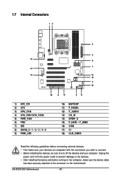
... and your devices are compliant with the connectors you wish to connect. • Before installing the devices, be sure to the connector on the motherboard. GA-M720-ES3 Motherboard - 20 - 1-7 Internal Connectors 13 5 2 12 8 7 14 13 10 15 4 18 16 6 17 9 11 1) ATX_12V 2) ATX 3) CPU_FAN 4) SYS_FAN1/SYS_FAN2 5) PWR_FAN 6) FDD 7) IDE 8) SATA2_0 / 1 / 2 / 3 / 4 / 5 9) PWR_LED 10...
... and your devices are compliant with the connectors you wish to connect. • Before installing the devices, be sure to the connector on the motherboard. GA-M720-ES3 Motherboard - 20 - 1-7 Internal Connectors 13 5 2 12 8 7 14 13 10 15 4 18 16 6 17 9 11 1) ATX_12V 2) ATX 3) CPU_FAN 4) SYS_FAN1/SYS_FAN2 5) PWR_FAN 6) FDD 7) IDE 8) SATA2_0 / 1 / 2 / 3 / 4 / 5 9) PWR_LED 10...