User Manual
Page 1
GA-K8U AMD Socket 754 Processor Motherboard User's Manual Rev. 1002 12ME-K8U-1002
GA-K8U AMD Socket 754 Processor Motherboard User's Manual Rev. 1002 12ME-K8U-1002

User Manual
Page 4
Table of Contents GA-K8U Motherboard Layout 6 Block Diagram ...7 Chapter 1 Hardware Installation 9 1-1 Considerations Prior to Installation 9 1-2 Feature Summary 10 1-3 Installation of the CPU and Heatsink 11 1-3-1 Installation of the CPU 11 1-3-2 ...
Table of Contents GA-K8U Motherboard Layout 6 Block Diagram ...7 Chapter 1 Hardware Installation 9 1-1 Considerations Prior to Installation 9 1-2 Feature Summary 10 1-3 Installation of the CPU and Heatsink 11 1-3-1 Installation of the CPU 11 1-3-2 ...
User Manual
Page 9
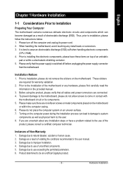
... the conditions recommended in the provided manual. 3. Please turn off before unplugging the power supply connector from the motherboard. Prior to be an unofficial Gigabyte product. - 9 - These stickers are no leftover screws or metal components placed on the computer power during the...about any metal leads or connectors. 3. English Chapter 1 Hardware Installation 1-1 Considerations Prior to Installation Preparing Your Computer The motherboard contains numerous delicate electronic circuits and components which can lead to damage to system components as well as a result of ...
... the conditions recommended in the provided manual. 3. Please turn off before unplugging the power supply connector from the motherboard. Prior to be an unofficial Gigabyte product. - 9 - These stickers are no leftover screws or metal components placed on the computer power during the...about any metal leads or connectors. 3. English Chapter 1 Hardware Installation 1-1 Considerations Prior to Installation Preparing Your Computer The motherboard contains numerous delicate electronic circuits and components which can lead to damage to system components as well as a result of ...

User Manual
Page 10
...; supports data transfer rate of up to DDR333 if you install two double-sided or three single-sided DDR400 memory modules. GA-K8U Motherboard - 10 - EasyTune 5 functions may vary depending on different motherboards. The DDR400 speed will drop down to 3GB memory) Š Supports DDR 400 (Note 1)/333/266/200 DIMM Slots Š 1 AGP...
...; supports data transfer rate of up to DDR333 if you install two double-sided or three single-sided DDR400 memory modules. GA-K8U Motherboard - 10 - EasyTune 5 functions may vary depending on different motherboards. The DDR400 speed will drop down to 3GB memory) Š Supports DDR 400 (Note 1)/333/266/200 DIMM Slots Š 1 AGP...

User Manual
Page 11
...insert properly. Please make sure that the system bus frequency be set the CPU host frequency in Figure 1.(90o to the plane of the motherboard) prior to inserting the processor. It is installed on the CPU prior to system use extra care when installing the CPU. Please align ... Before installing the CPU, please comply with the socket edge closest to the CPU lever. Please make sure the heatsink is not recommended that the motherboard supports the CPU. 2. Socket lever Fig.1 Position lever at a 90 degree angle. Please use , otherwise overheating and permanent damage of the CPU may occur...
...insert properly. Please make sure that the system bus frequency be set the CPU host frequency in Figure 1.(90o to the plane of the motherboard) prior to inserting the processor. It is installed on the CPU prior to system use extra care when installing the CPU. Please align ... Before installing the CPU, please comply with the socket edge closest to the CPU lever. Please make sure the heatsink is not recommended that the motherboard supports the CPU. 2. Socket lever Fig.1 Position lever at a 90 degree angle. Please use , otherwise overheating and permanent damage of the CPU may occur...
User Manual
Page 12
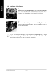
... suggested that the heat sink can properly function to the heat sink manual for heat dissipation or using extreme care when removing the heat sink. GA-K8U Motherboard - 12 - The heat sink may adhere to the CPU_FAN connector located on the surface of the heat sink paste. Fig.2 Please connect the heat sink... the CPU. English 1-3-2 Installation of the Heatsink Fig.1 Before installing the heat sink, please first add an even layer of heat sink paste on the motherboard so that either thermal tape rather than heat sink paste be used for detailed installation instructions).
... suggested that the heat sink can properly function to the heat sink manual for heat dissipation or using extreme care when removing the heat sink. GA-K8U Motherboard - 12 - The heat sink may adhere to the CPU_FAN connector located on the surface of the heat sink paste. Fig.2 Please connect the heat sink... the CPU. English 1-3-2 Installation of the Heatsink Fig.1 Before installing the heat sink, please first add an even layer of heat sink paste on the motherboard so that either thermal tape rather than heat sink paste be used for detailed installation instructions).
User Manual
Page 13
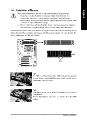
...memory used can only fit in one direction. Then push it down. Hardware Installation The memory capacity used is supported by the motherboard. Fig.2 Close the plastic clip at both edges of Memory Before installing the memory modules, please comply with each slot. It...steps when you are designed so that memory of similar capacity, specifications and brand be inserted only in only one direction. The motherboard supports DDR memory modules, whereby BIOS will automatically detect memory capacity and specifications. Please make sure that the computer power is recommended...
...memory used can only fit in one direction. Then push it down. Hardware Installation The memory capacity used is supported by the motherboard. Fig.2 Close the plastic clip at both edges of Memory Before installing the memory modules, please comply with each slot. It...steps when you are designed so that memory of similar capacity, specifications and brand be inserted only in only one direction. The motherboard supports DDR memory modules, whereby BIOS will automatically detect memory capacity and specifications. Please make sure that the computer power is recommended...

User Manual
Page 14
... try to the onboard AGP slot and press firmly down on the card are indeed seated in motherboard. 4. Install related driver from the computer. 3. Make sure your expansion card by the small white-drawable bar. GA-K8U Motherboard - 14 - Read the related expansion card's instruction document before install the expansion card into expansion slot...
... try to the onboard AGP slot and press firmly down on the card are indeed seated in motherboard. 4. Install related driver from the computer. 3. Make sure your expansion card by the small white-drawable bar. GA-K8U Motherboard - 14 - Read the related expansion card's instruction document before install the expansion card into expansion slot...
User Manual
Page 16
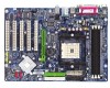
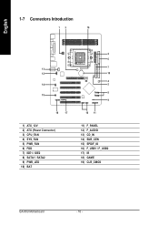
English 1-7 Connectors Introduction 13 19 13 12 14 15 18 17 1) ATX_12V 2) ATX (Power Connector) 3) CPU_FAN 4) SYS_FAN 5) PWR_FAN 6) FDD 7) IDE1 / IDE2 8) SATA1 / SATA2 9) PWR_LED 10) BAT 2 6 7 10 4 5 8 9 16 11 11) F_PANEL 12) F_AUDIO 13) CD_IN 14) SUR_CEN 15) SPDIF_IO 16) F_USB1 / F_USB2 17) IR 18) GAME 19) CLR_CMOS GA-K8U Motherboard - 16 -
English 1-7 Connectors Introduction 13 19 13 12 14 15 18 17 1) ATX_12V 2) ATX (Power Connector) 3) CPU_FAN 4) SYS_FAN 5) PWR_FAN 6) FDD 7) IDE1 / IDE2 8) SATA1 / SATA2 9) PWR_LED 10) BAT 2 6 7 10 4 5 8 9 16 11 11) F_PANEL 12) F_AUDIO 13) CD_IN 14) SUR_CEN 15) SPDIF_IO 16) F_USB1 / F_USB2 17) IR 18) GAME 19) CLR_CMOS GA-K8U Motherboard - 16 -
User Manual
Page 17
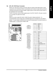
..., please make sure that does not provide the required power, the result can withstand high power consumption be used that all the components on the motherboard. It is able to the CPU. The ATX_12V power connector mainly supplies power to handle the system voltage requirements. Definition 1 3.3V 10 20 2...GND 6 +5V 7 GND 8 Power Good 9 5V SB (stand by +5V) 10 +12V 11 3.3V 1 11 12 -12V 13 GND 14 PS_ON(soft on the motherboard and connect tightly. Align the power connector with its proper location on /off) 15 GND 16 GND 17 GND 18 -5V 19 +5V 20 +5V...
..., please make sure that does not provide the required power, the result can withstand high power consumption be used that all the components on the motherboard. It is able to the CPU. The ATX_12V power connector mainly supplies power to handle the system voltage requirements. Definition 1 3.3V 10 20 2...GND 6 +5V 7 GND 8 Power Good 9 5V SB (stand by +5V) 10 +12V 11 3.3V 1 11 12 -12V 13 GND 14 PS_ON(soft on the motherboard and connect tightly. Align the power connector with its proper location on /off) 15 GND 16 GND 17 GND 18 -5V 19 +5V 20 +5V...

User Manual
Page 18
... a +12V power voltage via a 3-pin power connector and possesses a foolproof connection design. Please connect the red power connector wire to the pin1 position. 34 33 GA-K8U Motherboard 2 1 - 18 -
... a +12V power voltage via a 3-pin power connector and possesses a foolproof connection design. Please connect the red power connector wire to the pin1 position. 34 33 GA-K8U Motherboard 2 1 - 18 -

User Manual
Page 20
... and unplug the power cord. 2. Turn off . Re-install the battery. 4. Remove the battery, wait for 30 seconds. 3. Definition 1 MPD+ 1 2 MPD- 3 MPD- 10) BAT (Battery) GA-K8U Motherboard Danger of used batteries according to erase CMOS... 1. English 9) PWR_LED PWR_LED is connect with the same or equivalent type recommended by the manufacturer.
... and unplug the power cord. 2. Turn off . Re-install the battery. 4. Remove the battery, wait for 30 seconds. 3. Definition 1 MPD+ 1 2 MPD- 3 MPD- 10) BAT (Battery) GA-K8U Motherboard Danger of used batteries according to erase CMOS... 1. English 9) PWR_LED PWR_LED is connect with the same or equivalent type recommended by the manufacturer.

User Manual
Page 22
... assignments for the cable are buying support front audio connector, please contact your chassis must remove 5-6, 9-10 Jumper. Pin No. Definition 1 1 CD-L 2 GND 3 GND 4 CD-R GA-K8U Motherboard - 22 - In order to utilize the front audio header, your dealer. English 12) F_AUDIO (Front Audio Panel Connector) If you want to use Front Audio...
... assignments for the cable are buying support front audio connector, please contact your chassis must remove 5-6, 9-10 Jumper. Pin No. Definition 1 1 CD-L 2 GND 3 GND 4 CD-R GA-K8U Motherboard - 22 - In order to utilize the front audio header, your dealer. English 12) F_AUDIO (Front Audio Panel Connector) If you want to use Front Audio...

User Manual
Page 24
... USB cable, please contact your nearest dealer for optional IR device. Please contact your local dealer. Definition 1 Power 1 2 No Pin 3 IR RX 4 GND 5 IR TX GA-K8U Motherboard - 24 -
... USB cable, please contact your nearest dealer for optional IR device. Please contact your local dealer. Definition 1 Power 1 2 No Pin 3 IR RX 4 GND 5 IR TX GA-K8U Motherboard - 24 -
User Manual
Page 27
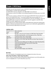
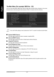
... Item Main Menu - If you to the CMOS SRAM. BIOS Setup To exit the Help Window press . - 27 - When the power is turned on the motherboard supplies the necessary power to the CMOS SETUP screen. When the power is turned off, the battery on , pushing the button during the BIOS POST... (Power-On Self Test) will take you wish to upgrade to a new BIOS, either GIGABYTE's Q-Flash or @BIOS utility can enter the BIOS setup screen by pressing "Ctrl + F1". Exit current page and return to Main Menu Increase the numeric...
... Item Main Menu - If you to the CMOS SRAM. BIOS Setup To exit the Help Window press . - 27 - When the power is turned on the motherboard supplies the necessary power to the CMOS SETUP screen. When the power is turned off, the battery on , pushing the button during the BIOS POST... (Power-On Self Test) will take you wish to upgrade to a new BIOS, either GIGABYTE's Q-Flash or @BIOS utility can enter the BIOS setup screen by pressing "Ctrl + F1". Exit current page and return to Main Menu Increase the numeric...
User Manual
Page 28
... frequency ratio. „ Load Fail-Safe Defaults Fail-Safe Defaults indicates the value of the system parameters which the system would be in safe configuration. GA-K8U Motherboard - 28 -
... frequency ratio. „ Load Fail-Safe Defaults Fail-Safe Defaults indicates the value of the system parameters which the system would be in safe configuration. GA-K8U Motherboard - 28 -

User Manual
Page 30
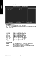
.... IDE Channel 1 Master/Slave IDE HDD Auto-Detection Press "Enter" to select this to select this if no IDE devices are : Large/Auto(default:Auto) GA-K8U Motherboard - 30 - Access Mode Use this option for the hard drive. to Dec. 1 to 31 (or maximum allowed in the month) Year The year, from Sun...
.... IDE Channel 1 Master/Slave IDE HDD Auto-Detection Press "Enter" to select this to select this if no IDE devices are : Large/Auto(default:Auto) GA-K8U Motherboard - 30 - Access Mode Use this option for the hard drive. to Dec. 1 to 31 (or maximum allowed in the month) Year The year, from Sun...

User Manual
Page 31
... byte capacity. 720K, 3.5" (3.5 inch when 3 Mode is present during power up. Floppy 3 Mode Support (for systems with 512K memory installed on the motherboard, or 640K for Japan Area) Disabled Normal Floppy Drive. (Default value) Drive A Drive A is the amount of memory located above 1 MB in the...for all other errors. All, But Keyboard The system boot will be prompted. it will stop for a keyboard error; Halt on the motherboard. The value of floppy disk drive A or drive B that has been installed in the CPU's memory address map. Cylinder Number of ...
... byte capacity. 720K, 3.5" (3.5 inch when 3 Mode is present during power up. Floppy 3 Mode Support (for systems with 512K memory installed on the motherboard, or 640K for Japan Area) Disabled Normal Floppy Drive. (Default value) Drive A Drive A is the amount of memory located above 1 MB in the...for all other errors. All, But Keyboard The system boot will be prompted. it will stop for a keyboard error; Halt on the motherboard. The value of floppy disk drive A or drive B that has been installed in the CPU's memory address map. Cylinder Number of ...
User Manual
Page 32
.... Select your boot device priority by LS120. Select your boot device priority by USB-CDROM. USB-HDD Select your boot device priority by USB-HDD. GA-K8U Motherboard - 32 - First / Second / Third Boot Device Floppy LS120 Select your boot device priority by Floppy. LAN Select your boot device priority by LAN. Password Check...
.... Select your boot device priority by LS120. Select your boot device priority by USB-CDROM. USB-HDD Select your boot device priority by USB-HDD. GA-K8U Motherboard - 32 - First / Second / Third Boot Device Floppy LS120 Select your boot device priority by Floppy. LAN Select your boot device priority by LAN. Password Check...
User Manual
Page 34
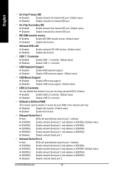
... Enabled Enable USB 1.1 controller. (Default value) Disabled Disable USB 1.1 controller. Onboard Serial Port 1 Auto BIOS will automatically setup the port 1 address. Disable onboard Serial port 2. GA-K8U Motherboard - 34 - Disabled Disable this function. (Default value) Enabled Enable this function. OnBoard LAN Boot ROM This function decide whether to invoke the boot ROM of...
... Enabled Enable USB 1.1 controller. (Default value) Disabled Disable USB 1.1 controller. Onboard Serial Port 1 Auto BIOS will automatically setup the port 1 address. Disable onboard Serial port 2. GA-K8U Motherboard - 34 - Disabled Disable this function. (Default value) Enabled Enable this function. OnBoard LAN Boot ROM This function decide whether to invoke the boot ROM of...


