User Manual
Page 6
English Table of Content Read Me First 4 Chapter 1 Introduction 8 Features Summary 8 GA-K8NSNXP Motherboard Layout 10 Block Diagram 11 Chapter 2 Hardware Installation Process 13 Step 1: Install the Central Processing Unit (CPU 14 Step ... Back Panel Introduction 19 Step 4-2: Connectors Introduction 21 Chapter 3 BIOS Setup 37 The Main Menu (For example: BIOS Ver. : E12 38 Standard CMOS Features 40 Advanced BIOS Features 42 Integrated Peripherals 44 Power Management Setup 48 PnP/PCI Configurations 50 PC Health Status 51 Frequency/Voltage Control 52 GA-K8NSNXP Motherboard - 6 -
English Table of Content Read Me First 4 Chapter 1 Introduction 8 Features Summary 8 GA-K8NSNXP Motherboard Layout 10 Block Diagram 11 Chapter 2 Hardware Installation Process 13 Step 1: Install the Central Processing Unit (CPU 14 Step ... Back Panel Introduction 19 Step 4-2: Connectors Introduction 21 Chapter 3 BIOS Setup 37 The Main Menu (For example: BIOS Ver. : E12 38 Standard CMOS Features 40 Advanced BIOS Features 42 Integrated Peripherals 44 Power Management Setup 48 PnP/PCI Configurations 50 PC Health Status 51 Frequency/Voltage Control 52 GA-K8NSNXP Motherboard - 6 -

User Manual
Page 7
Table of Content Channel Audio Function Introduction 66 Jack-Sensing and UAJ Introduction 72 Xpress Recovery Introduction 74 Serial ATA BIOS Setting Utility Introduction 77 Chapter 5 Appendix 83 - 7 - English Top Performance 53 Load Fail-Safe Defaults 53 Load Optimized Defaults 54 Set Supervisor/User Password 54 Exit Without Saving 55 Save & Exit Setup 55 Chapter 4 Technical Reference 57 @BIOS™ Introduction 57 K8 DPS (Dual Power System) Introduction 58 Flash BIOS Method Introduction 59 2- / 4- / 6- / 8-
Table of Content Channel Audio Function Introduction 66 Jack-Sensing and UAJ Introduction 72 Xpress Recovery Introduction 74 Serial ATA BIOS Setting Utility Introduction 77 Chapter 5 Appendix 83 - 7 - English Top Performance 53 Load Fail-Safe Defaults 53 Load Optimized Defaults 54 Set Supervisor/User Password 54 Exit Without Saving 55 Save & Exit Setup 55 Chapter 4 Technical Reference 57 @BIOS™ Introduction 57 K8 DPS (Dual Power System) Introduction 58 Flash BIOS Method Introduction 59 2- / 4- / 6- / 8-

User Manual
Page 9
...IDE controller operation y Supports ATAPI mode for HDD y Supports IDE bus master operation y Supports ATA133/RAID mode switch by BIOS y Displays status and error checking messages during boot-up y Mirroring supports automatic background rebuilds y Features LBA and Extended Interrupt... 13 drive translation in controller onboard BIOS I/O Control y IT8712 Hardware Monitor y CPU/System/Power fan revolution detect y CPU/System/Power fan fail warning y CPU temperature...
...IDE controller operation y Supports ATAPI mode for HDD y Supports IDE bus master operation y Supports ATA133/RAID mode switch by BIOS y Displays status and error checking messages during boot-up y Mirroring supports automatic background rebuilds y Features LBA and Extended Interrupt... 13 drive translation in controller onboard BIOS I/O Control y IT8712 Hardware Monitor y CPU/System/Power fan revolution detect y CPU/System/Power fan fail warning y CPU temperature...
User Manual
Page 10
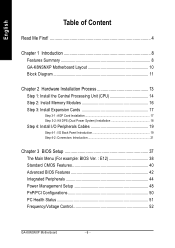
... RAM_LED ATX COMA LPT IDE2 PWR_FAN COMB USB LAN1 (Gigabit Ethernet) IDE1 GA-K8NSNXP ICS1883 AUDIO F_AUDIO CD_IN 2X_DET CODEC IT8712 AGP SUR_CEN SPDIF_IO SOCKET 754 SATA0_SB SATA1_SB PCI1 nVIDIA® nForce™ 3 250 PCI2 FDD BAT CLR_CMOS BACKUP BIOS MAIN BIOS NB_FAN F_USB2 Marvell 8001 SYS_FAN GAME IR_CIR INFO_LINK PCI3 TSB82AA2 PCI4 TSB81BA3...
... RAM_LED ATX COMA LPT IDE2 PWR_FAN COMB USB LAN1 (Gigabit Ethernet) IDE1 GA-K8NSNXP ICS1883 AUDIO F_AUDIO CD_IN 2X_DET CODEC IT8712 AGP SUR_CEN SPDIF_IO SOCKET 754 SATA0_SB SATA1_SB PCI1 nVIDIA® nForce™ 3 250 PCI2 FDD BAT CLR_CMOS BACKUP BIOS MAIN BIOS NB_FAN F_USB2 Marvell 8001 SYS_FAN GAME IR_CIR INFO_LINK PCI3 TSB82AA2 PCI4 TSB81BA3...

User Manual
Page 11
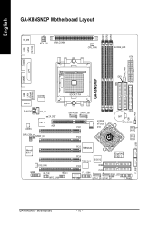
Introduction English Block Diagram AGP Slot 4X/8X AGPCLK (66MHz) AMD K8 Socket 754 CPU CPUCLK+/- (200MHz) System Bus 1600MHz DDR400/DDR333/266 DIMM DDR RAM 5 PCI LAN1 RJ45 LAN2 RJ45 Marvell 8001 ICS1883 TSB82AA2 SiI3512 TSB81BA3 2 Serial ATA 3 IEEE1394b nVIDIA nForceTM 3 250 8 USB Ports BIOS LPC BUS IT8712 IR_CIR Game Port Floppy LPT Port AC97 Link 24 MHz 33 MHz AC97 CODEC PS/2 KB/Mouse 2 COM Ports MIC LINE-IN LINE-OUT IT8212 IDE3 IDE4 PCICLK (33MHz) 2 Serial ATA ATA33/66/100/133 IDE Channels - 11 -
Introduction English Block Diagram AGP Slot 4X/8X AGPCLK (66MHz) AMD K8 Socket 754 CPU CPUCLK+/- (200MHz) System Bus 1600MHz DDR400/DDR333/266 DIMM DDR RAM 5 PCI LAN1 RJ45 LAN2 RJ45 Marvell 8001 ICS1883 TSB82AA2 SiI3512 TSB81BA3 2 Serial ATA 3 IEEE1394b nVIDIA nForceTM 3 250 8 USB Ports BIOS LPC BUS IT8712 IR_CIR Game Port Floppy LPT Port AC97 Link 24 MHz 33 MHz AC97 CODEC PS/2 KB/Mouse 2 COM Ports MIC LINE-IN LINE-OUT IT8212 IDE3 IDE4 PCICLK (33MHz) 2 Serial ATA ATA33/66/100/133 IDE Channels - 11 -
User Manual
Page 13
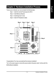
Hardware Installation Process Continue with the BIOS/software installation. - 13 - Install the Central Processing Unit (CPU) Step 2 - Install I/O Peripherals Cables Step 4 Step 3 Step 1 Step 2 Step 4 Step 3 Step 4 Congratulations! Install Expansion Cards Step 4 - Install Memory Modules Step 3 - You have accomplished the hardware installation! English Chapter 2 Hardware Installation Process To set up your computer, you must complete the following steps: Step 1 - Turn on the power supply or connect the power cable to the power outlet.
Hardware Installation Process Continue with the BIOS/software installation. - 13 - Install the Central Processing Unit (CPU) Step 2 - Install I/O Peripherals Cables Step 4 Step 3 Step 1 Step 2 Step 4 Step 3 Step 4 Congratulations! Install Expansion Cards Step 4 - Install Memory Modules Step 3 - You have accomplished the hardware installation! English Chapter 2 Hardware Installation Process To set up your computer, you must complete the following steps: Step 1 - Turn on the power supply or connect the power cable to the power outlet.
User Manual
Page 16
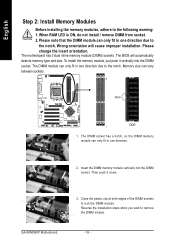
... ON, do not install / remove DIMM from socket. 2. GA-K8NSNXP Motherboard 3. Close the plastic clip at both edges of the DIMM sockets to the notch. To install the memory module, just push it down. The DIMM module can only fit in one direction. 2. The BIOS will cause improper installation. Notch DDR 1. Reverse the...
... ON, do not install / remove DIMM from socket. 2. GA-K8NSNXP Motherboard 3. Close the plastic clip at both edges of the DIMM sockets to the notch. To install the memory module, just push it down. The DIMM module can only fit in one direction. 2. The BIOS will cause improper installation. Notch DDR 1. Reverse the...

User Manual
Page 17
Press the expansion card firmly into the computer. 2. Be sure the metal contacts on the computer, if necessary, setup BIOS utility of expansion card from BIOS. 8. Replace the screw to secure the slot bracket of the AGP slot when you try to install / uninstall the AGP card. Replace your ... onboard AGP slot and press firmly down on the slot. When an AGP 2X (3.3V) card is not supported by the small white-drawable bar. GA-K8NSNXP Motherboard - 17 - Install related driver from the computer. 3. Make sure your AGP card is inserted. Informing users that system might not boot up , ...
Press the expansion card firmly into the computer. 2. Be sure the metal contacts on the computer, if necessary, setup BIOS utility of expansion card from BIOS. 8. Replace the screw to secure the slot bracket of the AGP slot when you try to install / uninstall the AGP card. Replace your ... onboard AGP slot and press firmly down on the slot. When an AGP 2X (3.3V) card is not supported by the small white-drawable bar. GA-K8NSNXP Motherboard - 17 - Install related driver from the computer. 3. Make sure your AGP card is inserted. Informing users that system might not boot up , ...
User Manual
Page 26
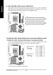
... IDE3 and IDE4, please use it in unity with the Pin1. GA-K8NSNXP Motherboard - 26 - English 9) IDE3 / IDE4 (IDE3 / IDE4 Connector, RAID/ATA133) The red stripe of the ribbon cable must be the same side with BIOS and install the correct driver to have proper operation. If you wish... to use RAID function, please use it in unity with BIOS (either RAID or ATA133). SATA0_SB / SATA1_SB 1 7 SATA0_SII / SATA1_SII 7 1 Pin No. 1 2 3 4 5 6 7 Definition GND TXP TXN GND RXN RXP GND These SATA connectors ...
... IDE3 and IDE4, please use it in unity with the Pin1. GA-K8NSNXP Motherboard - 26 - English 9) IDE3 / IDE4 (IDE3 / IDE4 Connector, RAID/ATA133) The red stripe of the ribbon cable must be the same side with BIOS and install the correct driver to have proper operation. If you wish... to use RAID function, please use it in unity with BIOS (either RAID or ATA133). SATA0_SB / SATA1_SB 1 7 SATA0_SII / SATA1_SII 7 1 Pin No. 1 2 3 4 5 6 7 Definition GND TXP TXN GND RXN RXP GND These SATA connectors ...
User Manual
Page 34
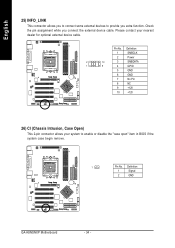
Pin No. Definition 1 Signal 2 GND GA-K8NSNXP Motherboard - 34 - Definition 1 SMBCLK 2 Power 2 10 3 SMBDATA 1 9 4 GPIO 5 GND 6 GND 7 No Pin 8 NC 9 +12V 10 +12V 26) CI (Chassis Intrusion, Case Open) This 2-pin connector ... the external device cable. English 25) INFO_LINK This connector allows you to connect some external devices to enable or disable the "case open" item in BIOS if the system case begin remove. 1 Pin No.
Pin No. Definition 1 Signal 2 GND GA-K8NSNXP Motherboard - 34 - Definition 1 SMBCLK 2 Power 2 10 3 SMBDATA 1 9 4 GPIO 5 GND 6 GND 7 No Pin 8 NC 9 +12V 10 +12V 26) CI (Chassis Intrusion, Case Open) This 2-pin connector ... the external device cable. English 25) INFO_LINK This connector allows you to connect some external devices to enable or disable the "case open" item in BIOS if the system case begin remove. 1 Pin No.

User Manual
Page 37
... the previous CMOS value from CMOS, only for Option Page Setup Menu Load the file-safe default CMOS value from BIOS default table Load the Optimized Defaults Dual BIOS/Q-Flash utility System Information Save all the CMOS changes, only for Main Menu - 37 - CONTROL KEYS Move to...modify the basic system configuration. Exit current page and return to enter Setup. To enter Advanced BIOS setting menu, press "Ctrl+F1" key on the BIOS screen. BIOS Setup English Chapter 3 BIOS Setup BIOS Setup is turned off. The program that it retains the Setup information when the power is ...
... the previous CMOS value from CMOS, only for Option Page Setup Menu Load the file-safe default CMOS value from BIOS default table Load the Optimized Defaults Dual BIOS/Q-Flash utility System Information Save all the CMOS changes, only for Main Menu - 37 - CONTROL KEYS Move to...modify the basic system configuration. Exit current page and return to enter Setup. To enter Advanced BIOS setting menu, press "Ctrl+F1" key on the BIOS screen. BIOS Setup English Chapter 3 BIOS Setup BIOS Setup is turned off. The program that it retains the Setup information when the power is ...
User Manual
Page 38
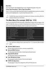
... described in standard compatible BIOS. The Main Menu (For example: BIOS Ver. : E12) Once you to search the advanced option hidden. If you can't find the setting you want, please press "Ctrl + F1" to select from the exact settings for your motherboard. GA-K8NSNXP Motherboard - 38 -... The Main Menu allows you enter Award BIOS CMOS Setup Utility, the Main Menu (as figure below) will appear on -line description of the highlighted ...
... described in standard compatible BIOS. The Main Menu (For example: BIOS Ver. : E12) Once you to search the advanced option hidden. If you can't find the setting you want, please press "Ctrl + F1" to select from the exact settings for your motherboard. GA-K8NSNXP Motherboard - 38 -... The Main Menu allows you enter Award BIOS CMOS Setup Utility, the Main Menu (as figure below) will appear on -line description of the highlighted ...

User Manual
Page 39
It allows you wish to the system. BIOS Setup z Set User Password Change, set , or disable password. English z PC Health Status This setup page is control CPU's clock and frequency ratio. z Load Fail-...
It allows you wish to the system. BIOS Setup z Set User Password Change, set , or disable password. English z PC Health Status This setup page is control CPU's clock and frequency ratio. z Load Fail-...
User Manual
Page 40
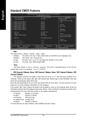
...127M 128M Item Help Menu Level` Change the day, month, year Sun. Jan. For example, 1 p.m. is calculated base on the 24-hour military-time clock. GA-K8NSNXP Motherboard - 40 - to 2098 KLJI: Move Enter: Select F5: Previous Values +/-/PU/PD: Value F10: Save F6: Fail-Safe Defaults ESC: Exit F1: ... will automatically detect HDD type. to Dec. 1 to 31 (or maximum allowed in the month) Year The year, from drive C to Sat, determined by the BIOS and is user-definable; Day The day, from 1 to 31 (or the maximum allowed in the month) < Ye a r > 1999 to Sat. Note that...
...127M 128M Item Help Menu Level` Change the day, month, year Sun. Jan. For example, 1 p.m. is calculated base on the 24-hour military-time clock. GA-K8NSNXP Motherboard - 40 - to 2098 KLJI: Move Enter: Select F5: Previous Values +/-/PU/PD: Value F10: Save F6: Fail-Safe Defaults ESC: Exit F1: ... will automatically detect HDD type. to Dec. 1 to 31 (or maximum allowed in the month) Year The year, from drive C to Sat, determined by the BIOS and is user-definable; Day The day, from 1 to 31 (or the maximum allowed in the month) < Ye a r > 1999 to Sat. Note that...

User Manual
Page 41
...boot will not stop for all other errors. This is present during power up. Both Drive A & B are 3 mode Floppy Drives. Extended Memory The BIOS determines how much extended memory is the amount of memory located above 1 MB in the computer. The value of the base memory is Enabled). 720K... on the motherboard, or 640K for a keyboard or disk error; All, But Disk/Key The system boot will be prompted. All Errors Whenever the BIOS detects a non-fatal error the system will not stop for any error that has been installed in the CPU's memory address map. - 41 -...
...boot will not stop for all other errors. This is present during power up. Both Drive A & B are 3 mode Floppy Drives. Extended Memory The BIOS determines how much extended memory is the amount of memory located above 1 MB in the computer. The value of the base memory is Enabled). 720K... on the motherboard, or 640K for a keyboard or disk error; All, But Disk/Key The system boot will be prompted. All Errors Whenever the BIOS detects a non-fatal error the system will not stop for any error that has been installed in the CPU's memory address map. - 41 -...
User Manual
Page 42
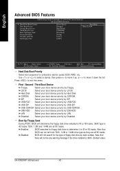
...priority by USB-ZIP. LAN Select your boot device priority by LAN. Boot Up Floppy Seek During POST, BIOS will determine the floppy disk drive installed is 40 or 80 tracks. 360K type is 40 tracks 720K, ...1.2M and 1.44M are all 80 tracks. Disabled BIOS will not be any warning message if the drive installed is 40 or 80 tracks. LS120 Select your boot... device, then press to move it up, or to move it is 360K. (Default value) GA-K8NSNXP Motherboard - 42 - Enabled BIOS searches for onboard(or add-on cards) SCSI, RAID, etc.
...priority by USB-ZIP. LAN Select your boot device priority by LAN. Boot Up Floppy Seek During POST, BIOS will determine the floppy disk drive installed is 40 or 80 tracks. 360K type is 40 tracks 720K, ...1.2M and 1.44M are all 80 tracks. Disabled BIOS will not be any warning message if the drive installed is 40 or 80 tracks. LS120 Select your boot... device, then press to move it up, or to move it is 360K. (Default value) GA-K8NSNXP Motherboard - 42 - Enabled BIOS searches for onboard(or add-on cards) SCSI, RAID, etc.

User Manual
Page 43
BIOS Setup AGP Set Init display first to AGP. (Default value) PCI slot Set Init display first to select the first initiation of the monitor display ...
BIOS Setup AGP Set Init display first to AGP. (Default value) PCI slot Set Init display first to select the first initiation of the monitor display ...

User Manual
Page 45
... IDE Enabled Enable onboard 1st channel IDE port. (Default value) Disabled Disable onboard 1st channel IDE port. USB Keyboard Support Enabled Enable USB keyboard support. BIOS Setup V1.1+V2.0 Enable USB 1.1 and USB 2.0 controller. (Default value) V1.1 Only enable USB 1.1 controller. Disabled Disable this function. (Default value) SATA Primary Master RAID...
... IDE Enabled Enable onboard 1st channel IDE port. (Default value) Disabled Disable onboard 1st channel IDE port. USB Keyboard Support Enabled Enable USB keyboard support. BIOS Setup V1.1+V2.0 Enable USB 1.1 and USB 2.0 controller. (Default value) V1.1 Only enable USB 1.1 controller. Disabled Disable this function. (Default value) SATA Primary Master RAID...
User Manual
Page 46
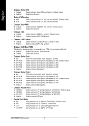
... onboard Serial port 2 and address is 3E8. 2E8/IRQ3 Enable onboard Serial port 2 and address is 2E8. Onboard Serial Port 2 Auto BIOS will automatically setup the port 1 address. 3F8/IRQ4 Enable onboard Serial port 1 and address is 3F8. (Default value) 2F8/IRQ3 Enable onboard...value) 278/IRQ5 Enable onboard LPT port and address is 278/IRQ5. 3BC/IRQ7 Enable onboard LPT port and address is 3BC/IRQ7. GA-K8NSNXP Motherboard - 46 - English Onboard Serial ATA Enabled Enable onboard Serial ATA chip function. (Default value) Disabled Disable this function. Disabled Disable...
... onboard Serial port 2 and address is 3E8. 2E8/IRQ3 Enable onboard Serial port 2 and address is 2E8. Onboard Serial Port 2 Auto BIOS will automatically setup the port 1 address. 3F8/IRQ4 Enable onboard Serial port 1 and address is 3F8. (Default value) 2F8/IRQ3 Enable onboard...value) 278/IRQ5 Enable onboard LPT port and address is 278/IRQ5. 3BC/IRQ7 Enable onboard LPT port and address is 3BC/IRQ7. GA-K8NSNXP Motherboard - 46 - English Onboard Serial ATA Enabled Enable onboard Serial ATA chip function. (Default value) Disabled Disable this function. Disabled Disable...

User Manual
Page 49
... Always in off state when AC back. (Default value) Full-On Always power on your keyboard, you can press the key to power on password. BIOS Setup Keyboard 98 If there is a "POWER" button on your system. Power On by Keyboard Disabled Disabled this function. (Default value) Double Click Double click...
... Always in off state when AC back. (Default value) Full-On Always power on your keyboard, you can press the key to power on password. BIOS Setup Keyboard 98 If there is a "POWER" button on your system. Power On by Keyboard Disabled Disabled this function. (Default value) Double Click Double click...


