
User Manual
Page 1
... out of date before publication of the specifications might be reproduced or transmitted in this motherboard. Due to update the information contained herein. GA-K8NS Ultra-939 AMD Socket 939 Processor Motherboard User's Manual Rev. 1002 12ME-K8NSU939-1002 Copyright © 2004 GIGABYTE TECHNOLOGY CO., LTD Copyright by GIGA-BYTE TECHNOLOGY CO., LTD. ("GBT"). Notice Please do not...
... out of date before publication of the specifications might be reproduced or transmitted in this motherboard. Due to update the information contained herein. GA-K8NS Ultra-939 AMD Socket 939 Processor Motherboard User's Manual Rev. 1002 12ME-K8NSU939-1002 Copyright © 2004 GIGABYTE TECHNOLOGY CO., LTD Copyright by GIGA-BYTE TECHNOLOGY CO., LTD. ("GBT"). Notice Please do not...

User Manual
Page 3
Motherboard GA-K8NS Ultra-939 Oct. 7, 2004
Motherboard GA-K8NS Ultra-939 Oct. 7, 2004
User Manual
Page 4
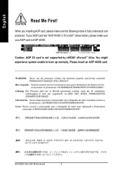
English Read Me First! You might experience system unable to boot up normally. When you installing AGP card, please make sure your AGP card is fully understood and practiced. GA-K8NS Ultra-939 Motherboard - 4 - If your AGP card has "AGP 4X/8X (1.5V) notch" (show below), please make sure the following notice is AGP 4X/8X. AGP 4X/8X notch Caution: AGP 2X card is not supported by nVIDIA® nForce3TM Ultra. Please insert an AGP 4X/8X card.
English Read Me First! You might experience system unable to boot up normally. When you installing AGP card, please make sure your AGP card is fully understood and practiced. GA-K8NS Ultra-939 Motherboard - 4 - If your AGP card has "AGP 4X/8X (1.5V) notch" (show below), please make sure the following notice is AGP 4X/8X. AGP 4X/8X notch Caution: AGP 2X card is not supported by nVIDIA® nForce3TM Ultra. Please insert an AGP 4X/8X card.

User Manual
Page 5
... to isolate the screw from static electricity, you should follow some precautions whenever you plug in or remove the ATX power connector on the motherboard. If you do not become alarmed you can still attach the spacers to a metal object, such as the power supply case. 3....computer when working on the inside. 2. In this way you can still attach the motherboard to the chassis... Computer motherboards and expansion cards contain very delicate Integrated Circuit (IC) chips. If the motherboard has mounting holes, but they don't line up with the components whenever the components ...
... to isolate the screw from static electricity, you should follow some precautions whenever you plug in or remove the ATX power connector on the motherboard. If you do not become alarmed you can still attach the spacers to a metal object, such as the power supply case. 3....computer when working on the inside. 2. In this way you can still attach the motherboard to the chassis... Computer motherboards and expansion cards contain very delicate Integrated Circuit (IC) chips. If the motherboard has mounting holes, but they don't line up with the components whenever the components ...
User Manual
Page 6
English Table of Contents Read Me First 4 Chapter 1 Introduction 8 Features Summary 8 GA-K8NS Ultra-939 Motherboard Layout 10 Block Diagram 11 Chapter 2 Hardware Installation Process 13 Step 1: Install the Central Processing Unit (CPU 14 Step 2: Install Memory Modules 16 Step 3: Install ... Features 38 Advanced BIOS Features 40 Integrated Peripherals 42 Power Management Setup 46 PnP/PCI Configurations 48 PC Health Status 49 MB Intelligent Tweaker(M.I.T 50 GA-K8NS Ultra-939 Motherboard - 6 -
English Table of Contents Read Me First 4 Chapter 1 Introduction 8 Features Summary 8 GA-K8NS Ultra-939 Motherboard Layout 10 Block Diagram 11 Chapter 2 Hardware Installation Process 13 Step 1: Install the Central Processing Unit (CPU 14 Step 2: Install Memory Modules 16 Step 3: Install ... Features 38 Advanced BIOS Features 40 Integrated Peripherals 42 Power Management Setup 46 PnP/PCI Configurations 48 PC Health Status 49 MB Intelligent Tweaker(M.I.T 50 GA-K8NS Ultra-939 Motherboard - 6 -
User Manual
Page 8
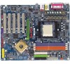
GA-K8NS Ultra-939 Motherboard - 8 - For example, 4 GB of memory size will instead be continued... (Note 1) Due to standard PC architecture, a certain amount of memory is reserved for IR/CIR y 1... Althlon™ 64 / 64FX processor (K8) y 2000MHz system bus y Supports core frequencies in excess of 2 FDD devices y 4 Serial ATA connectors y 2 ports from nVIDIA® nForce3TM Ultra controller (SATA0_SB, SATA1_SB); 2 ports from SiI3512 controller (SATA0_SII, SATA1_SII) y 1 parallel port supporting Normal/EPP/ECP mode y 2 Serial ports (COMA & COMB) y 8 USB 2.0/1.1 ports (rear x 4, front x 4...
GA-K8NS Ultra-939 Motherboard - 8 - For example, 4 GB of memory size will instead be continued... (Note 1) Due to standard PC architecture, a certain amount of memory is reserved for IR/CIR y 1... Althlon™ 64 / 64FX processor (K8) y 2000MHz system bus y Supports core frequencies in excess of 2 FDD devices y 4 Serial ATA connectors y 2 ports from nVIDIA® nForce3TM Ultra controller (SATA0_SB, SATA1_SB); 2 ports from SiI3512 controller (SATA0_SII, SATA1_SII) y 1 parallel port supporting Normal/EPP/ECP mode y 2 Serial ports (COMA & COMB) y 8 USB 2.0/1.1 ports (rear x 4, front x 4...
User Manual
Page 14
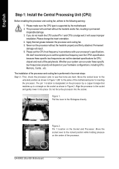
... specific bus frequencies are bent. Move the socket lever to the locked position while holding pressure on the center of the motherboard) prior to the plane of the processor. The processor will cause improper installation. Move the socket lever to the unlocked position... system can run the processor without the heatsink and/or fan, resulting in Figure 2. Pin 1 location on the processor by the motherboard. 2. GA-K8NS Ultra-939 Motherboard - 14 - If you to the socket and gently lower it will overheat without the heatsink properly and firmly attached. Whether your ...
... specific bus frequencies are bent. Move the socket lever to the locked position while holding pressure on the center of the motherboard) prior to the plane of the processor. The processor will cause improper installation. Move the socket lever to the unlocked position... system can run the processor without the heatsink and/or fan, resulting in Figure 2. Pin 1 location on the processor by the motherboard. 2. GA-K8NS Ultra-939 Motherboard - 14 - If you to the socket and gently lower it will overheat without the heatsink properly and firmly attached. Whether your ...
User Manual
Page 15
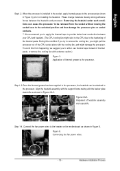
... power wires. - 15 - Application of heatsink assembly with the backer plate standoffs as shown in Figure 6. Alignment of thermal grease to the header on the motherboard as shown in Figure 3) prior to the hardening of the thermal paste. Connect the fan power wires to the processor. Step 1-3.Once the thermal grease...
... power wires. - 15 - Application of heatsink assembly with the backer plate standoffs as shown in Figure 6. Alignment of thermal grease to the header on the motherboard as shown in Figure 3) prior to the hardening of the thermal paste. Connect the fan power wires to the processor. Step 1-3.Once the thermal grease...
User Manual
Page 16
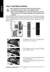
..., so the DIMM memory module can only fit in one direction. 2. Reverse the installation steps when you wish to lock the DIMM module. GA-K8NS Ultra-939 Motherboard - 16 - Close the plastic clip at both edges of the DIMM sockets to remove the DIMM module. The DIMM module can vary between ...not install / remove DIMM from socket. 2. English Step 2: Install Memory Modules Before installing the memory modules, adhere to the notch. The motherboard has 4 dual inline memory module (DIMM) sockets. Notch DDR 1. Insert the DIMM memory module vertically into the DIMM socket.
..., so the DIMM memory module can only fit in one direction. 2. Reverse the installation steps when you wish to lock the DIMM module. GA-K8NS Ultra-939 Motherboard - 16 - Close the plastic clip at both edges of the DIMM sockets to remove the DIMM module. The DIMM module can vary between ...not install / remove DIMM from socket. 2. English Step 2: Install Memory Modules Before installing the memory modules, adhere to the notch. The motherboard has 4 dual inline memory module (DIMM) sockets. Notch DDR 1. Insert the DIMM memory module vertically into the DIMM socket.
User Manual
Page 18
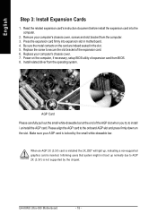
... users that system might not boot up , indicating a non-supported graphics card is locked by the chipset. Power on the card are indeed seated in motherboard. 4. Remove your computer's chassis cover. 7. Please align the AGP card to AGP 2X (3.3V) is installed the 2X_DET will light up normally due to the... the slot bracket of expansion card from the operating system. When an AGP 2X (3.3V) card is not supported by the small white-drawable bar. GA-K8NS Ultra-939 Motherboard - 18 -
... users that system might not boot up , indicating a non-supported graphics card is locked by the chipset. Power on the card are indeed seated in motherboard. 4. Remove your computer's chassis cover. 7. Please align the AGP card to AGP 2X (3.3V) is installed the 2X_DET will light up normally due to the... the slot bracket of expansion card from the operating system. When an AGP 2X (3.3V) card is not supported by the small white-drawable bar. GA-K8NS Ultra-939 Motherboard - 18 -

User Manual
Page 20
.... Have a standard USB interface. Devices like CD-ROM, walkman etc. If you want to enable 8-channel function you can be connected to MIC In jack. GA-K8NS Ultra-939 Motherboard - 20 - LAN1 connector is fast Ethernet with 10/100/ 1000 Mbps speed. can refer to page 30, and contact your nearest dealer for possible patch...
.... Have a standard USB interface. Devices like CD-ROM, walkman etc. If you want to enable 8-channel function you can be connected to MIC In jack. GA-K8NS Ultra-939 Motherboard - 20 - LAN1 connector is fast Ethernet with 10/100/ 1000 Mbps speed. can refer to page 30, and contact your nearest dealer for possible patch...
User Manual
Page 22
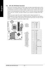
... GND 6 VCC 7 GND 8 Power Good 9 5V SB (stand by +5V) 10 +12V 11 3.3V 12 -12V 1 11 13 GND 14 PS_ON(soft on the motherboard and connect tightly. If the ATX_12V power connector is not connected, the system will not start . The ATX_12V power connector mainly supplies power to the...are properly installed. Align the power connector with its proper location on /off) 15 GND 16 GND 17 GND 18 -5V 19 VCC 20 VCC GA-K8NS Ultra-939 Motherboard - 22 - If a power supply is used (300W or greater). Please use of the power connector, the power supply can lead to an ...
... GND 6 VCC 7 GND 8 Power Good 9 5V SB (stand by +5V) 10 +12V 11 3.3V 12 -12V 1 11 13 GND 14 PS_ON(soft on the motherboard and connect tightly. If the ATX_12V power connector is not connected, the system will not start . The ATX_12V power connector mainly supplies power to the...are properly installed. Align the power connector with its proper location on /off) 15 GND 16 GND 17 GND 18 -5V 19 VCC 20 VCC GA-K8NS Ultra-939 Motherboard - 22 - If a power supply is used (300W or greater). Please use of the power connector, the power supply can lead to an ...
User Manual
Page 24
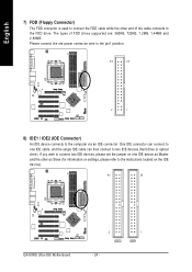
If you wish to connect two IDE devices, please set the jumper on the IDE device). 40 39 GA-K8NS Ultra-939 Motherboard 2 IDE2 1 IDE1 - 24 - English 7) FDD (Floppy Connector) The FDD connector is used to connect the FDD cable while the other as Slave (for information on ...
If you wish to connect two IDE devices, please set the jumper on the IDE device). 40 39 GA-K8NS Ultra-939 Motherboard 2 IDE2 1 IDE1 - 24 - English 7) FDD (Floppy Connector) The FDD connector is used to connect the FDD cable while the other as Slave (for information on ...

User Manual
Page 26
.... Pin 3: NC Pin 4: Data(-) Open: Normal Operation Close: Reset Hardware System Open: Normal Operation Close: Power On/Off Pin 1: LED anode(+) Pin 2: LED cathode(-) NC GA-K8NS Ultra-939 Motherboard - 26 - HDHD+ Reset Switch IDE Hard Disk Active LED HD (IDE Hard Disk Active LED) (Blue) SPK (Speaker Connector) (Amber) RES (Reset Switch) (Green) PW...
.... Pin 3: NC Pin 4: Data(-) Open: Normal Operation Close: Reset Hardware System Open: Normal Operation Close: Power On/Off Pin 1: LED anode(+) Pin 2: LED cathode(-) NC GA-K8NS Ultra-939 Motherboard - 26 - HDHD+ Reset Switch IDE Hard Disk Active LED HD (IDE Hard Disk Active LED) (Blue) SPK (Speaker Connector) (Amber) RES (Reset Switch) (Green) PW...

User Manual
Page 28
... order to play sound. 10 9 21 Pin No. 1 2 3 4 5 6 7 8 9 10 Definition MIC GND MIC_BIAS Power Front Audio (R) Rear Audio (R) Reserved No Pin Front Audio (L) Rear Audio (L) GA-K8NS Ultra-939 Motherboard - 28 - Informing users that system might not boot up , indicating a non-supported graphics card is the same as the pin assigment on the MB header.
... order to play sound. 10 9 21 Pin No. 1 2 3 4 5 6 7 8 9 10 Definition MIC GND MIC_BIAS Power Front Audio (R) Rear Audio (R) Reserved No Pin Front Audio (L) Rear Audio (L) GA-K8NS Ultra-939 Motherboard - 28 - Informing users that system might not boot up , indicating a non-supported graphics card is the same as the pin assigment on the MB header.
User Manual
Page 30
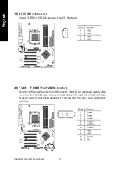
... unable to the CD_IN connector. 1 Pin No. Definition 2 10 1 Power 1 9 2 Power 3 USB Dx- 4 USB Dy- 5 USB Dx+ 6 USB Dy+ 7 GND 8 GND 9 No Pin 10 NC GA-K8NS Ultra-939 Motherboard - 30 - Pin No. For optional front USB cable, please contact your local dealer.
... unable to the CD_IN connector. 1 Pin No. Definition 2 10 1 Power 1 9 2 Power 3 USB Dx- 4 USB Dy- 5 USB Dx+ 6 USB Dy+ 7 GND 8 GND 9 No Pin 10 NC GA-K8NS Ultra-939 Motherboard - 30 - Pin No. For optional front USB cable, please contact your local dealer.
User Manual
Page 32
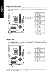
Definition 1 SMBCLK 2 VCC 2 10 3 SMBDATA 1 9 4 GPIO 5 GND 6 GND 7 No Pin 8 NC 9 +12V 10 +12V GA-K8NS Ultra-939 Motherboard - 32 - English 23) GAME (Game Connector) This connector supports joystick, MIDI keyboard and other relate audio devices. Pin No. Please contact your nearest dealer for ...
Definition 1 SMBCLK 2 VCC 2 10 3 SMBDATA 1 9 4 GPIO 5 GND 6 GND 7 No Pin 8 NC 9 +12V 10 +12V GA-K8NS Ultra-939 Motherboard - 32 - English 23) GAME (Game Connector) This connector supports joystick, MIDI keyboard and other relate audio devices. Pin No. Please contact your nearest dealer for ...
User Manual
Page 36
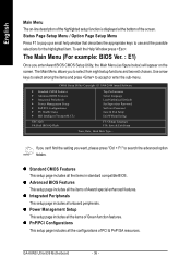
... of PCI & PnP ISA resources. The Main Menu (For example: BIOS Ver. : E1) Once you to use and the possible selections for the highlighted item. GA-K8NS Ultra-939 Motherboard - 36 - If you can't find the setting you want, please press "Ctrl + F1" to accept or enter the sub-menu. z Advanced BIOS Features This setup...
... of PCI & PnP ISA resources. The Main Menu (For example: BIOS Ver. : E1) Once you to use and the possible selections for the highlighted item. GA-K8NS Ultra-939 Motherboard - 36 - If you can't find the setting you want, please press "Ctrl + F1" to accept or enter the sub-menu. z Advanced BIOS Features This setup...
User Manual
Page 38
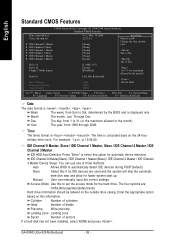
... if no IDE devices are : CHS/LBA/Large/Auto(default:Auto) Hard drive information should be labeled on this option for faster system start up. GA-K8NS Ultra-939 Motherboard - 38 - Week The week, from 1 to Sat. For example, 1 p.m. Day The day, from Sun to select this information. The time is , , , . IDE Channel 0 Master(Slave...
... if no IDE devices are : CHS/LBA/Large/Auto(default:Auto) Hard drive information should be labeled on this option for faster system start up. GA-K8NS Ultra-939 Motherboard - 38 - Week The week, from 1 to Sat. For example, 1 p.m. Day The day, from Sun to select this information. The time is , , , . IDE Channel 0 Master(Slave...
User Manual
Page 39
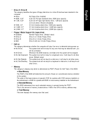
Both Drive A & B are 3 mode Floppy Drives. Halt on the motherboard, or 640K for a keyboard error; All, But Keyboard The system boot will not stop for systems with 512K memory installed on The category determines whether ... stop for Japan Area) Disabled Normal Floppy Drive. (Default value) Drive A Drive A is typically 512K for systems with 640K or more memory installed on the motherboard. The value of the base memory is 3 mode Floppy Drive. Memory The category is display-only which is 3 mode Floppy Drive. Base Memory The POST...
Both Drive A & B are 3 mode Floppy Drives. Halt on the motherboard, or 640K for a keyboard error; All, But Keyboard The system boot will not stop for systems with 512K memory installed on The category determines whether ... stop for Japan Area) Disabled Normal Floppy Drive. (Default value) Drive A Drive A is typically 512K for systems with 640K or more memory installed on the motherboard. The value of the base memory is 3 mode Floppy Drive. Memory The category is display-only which is 3 mode Floppy Drive. Base Memory The POST...


