User Manual
Page 6
... 8 GA-K8NS Ultra-939 Motherboard Layout 10 Block Diagram 11 Chapter 2 Hardware Installation Process 13 Step 1: Install the Central Processing Unit (CPU 14 Step 2: Install Memory Modules 16 Step 3: Install Expansion Cards 18 Step 4: Install I/O Peripherals Cables 19 Step 4-1: I/O Back Panel Introduction 19 Step 4-2: Connectors Introduction 21 Chapter 3 BIOS Setup 35 The Main Menu (For example: BIOS Ver. : E1 36 Standard CMOS Features 38 Advanced BIOS Features 40 Integrated Peripherals 42 Power Management Setup 46 PnP/PCI Configurations 48...
... 8 GA-K8NS Ultra-939 Motherboard Layout 10 Block Diagram 11 Chapter 2 Hardware Installation Process 13 Step 1: Install the Central Processing Unit (CPU 14 Step 2: Install Memory Modules 16 Step 3: Install Expansion Cards 18 Step 4: Install I/O Peripherals Cables 19 Step 4-1: I/O Back Panel Introduction 19 Step 4-2: Connectors Introduction 21 Chapter 3 BIOS Setup 35 The Main Menu (For example: BIOS Ver. : E1 36 Standard CMOS Features 38 Advanced BIOS Features 40 Integrated Peripherals 42 Power Management Setup 46 PnP/PCI Configurations 48...
User Manual
Page 8
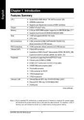
... CPU Chipset Memory Slots IDE Connections FDD Connections Onboard SATA Peripherals Onboard LAN y Socket 939 for AMD Althlon™ 64 / 64FX processor (K8) y 2000MHz system bus y Supports core frequencies in excess of 3000+ and faster y nVIDIA® nForce3TM Ultra y 4 184-pin DDR DIMM sockets, support up to be shown as 3.xxGB memory during system startup. For example, 4 GB of memory size will instead be continued... (Note 1) Due to standard PC architecture, a certain amount of 2 FDD devices y 4 Serial ATA connectors y 2 ports...
... CPU Chipset Memory Slots IDE Connections FDD Connections Onboard SATA Peripherals Onboard LAN y Socket 939 for AMD Althlon™ 64 / 64FX processor (K8) y 2000MHz system bus y Supports core frequencies in excess of 3000+ and faster y nVIDIA® nForce3TM Ultra y 4 184-pin DDR DIMM sockets, support up to be shown as 3.xxGB memory during system startup. For example, 4 GB of memory size will instead be continued... (Note 1) Due to standard PC architecture, a certain amount of 2 FDD devices y 4 Serial ATA connectors y 2 ports...
User Manual
Page 13
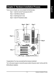
Install I/O Peripherals Cables Step 4 Step 1 Step 2 Step 4 Step 3 Step 4 Congratulations! Turn on the power supply or connect the power cable to the power outlet. Continue with the BIOS/software installation. - 13 - Install the Central Processing Unit (CPU) Step 2 - You have accomplished the hardware installation! Install Expansion Cards Step 4 - English Chapter 2 Hardware Installation Process To set up your computer, you must complete the following steps: Step 1 - Hardware Installation Process Install Memory Modules Step 3 -
Install I/O Peripherals Cables Step 4 Step 1 Step 2 Step 4 Step 3 Step 4 Congratulations! Turn on the power supply or connect the power cable to the power outlet. Continue with the BIOS/software installation. - 13 - Install the Central Processing Unit (CPU) Step 2 - You have accomplished the hardware installation! Install Expansion Cards Step 4 - English Chapter 2 Hardware Installation Process To set up your computer, you must complete the following steps: Step 1 - Hardware Installation Process Install Memory Modules Step 3 -
User Manual
Page 14
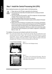
... specific bus frequencies properly will result. 6. The installation of the processor and cooling fan is supported by a copper triangle that none are not the standard specifications for CPU, chipset and most of the processor. Move the socket lever to set the CPU host frequency in four main steps: Step1-1. Socket Lever Pull the lever to the following warning: 1. GA-K8NS Ultra-939 Motherboard - 14 - Whether your system can run the processor without the heatsink...
... specific bus frequencies properly will result. 6. The installation of the processor and cooling fan is supported by a copper triangle that none are not the standard specifications for CPU, chipset and most of the processor. Move the socket lever to set the CPU host frequency in four main steps: Step1-1. Socket Lever Pull the lever to the following warning: 1. GA-K8NS Ultra-939 Motherboard - 14 - Whether your system can run the processor without the heatsink...
User Manual
Page 16
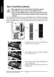
... the DIMM sockets to remove the DIMM module. GA-K8NS Ultra-939 Motherboard - 16 - Please note that the DIMM module can only fit in one direction. 2. The motherboard has 4 dual inline memory module (DIMM) sockets. Insert the DIMM memory module vertically into the DIMM socket. Then push it vertically into the DIMM socket. When RAM LED is ON, do not install / remove DIMM from socket. 2. Reverse the installation steps when...
... the DIMM sockets to remove the DIMM module. GA-K8NS Ultra-939 Motherboard - 16 - Please note that the DIMM module can only fit in one direction. 2. The motherboard has 4 dual inline memory module (DIMM) sockets. Insert the DIMM memory module vertically into the DIMM socket. Then push it vertically into the DIMM socket. When RAM LED is ON, do not install / remove DIMM from socket. 2. Reverse the installation steps when...
User Manual
Page 18
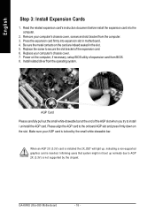
... in motherboard. 4. Install related driver from the computer. 3. Read the related expansion card's instruction document before install the expansion card into expansion slot in the slot. 5. Press the expansion card firmly into the computer. 2. GA-K8NS Ultra-939 Motherboard - 18 - English Step 3: Install Expansion Cards 1. Informing users that system might not boot up , indicating a non-supported graphics card is locked by the chipset. Remove your computer's chassis cover. 7. Replace the screw to install / uninstall the AGP card. Make...
... in motherboard. 4. Install related driver from the computer. 3. Read the related expansion card's instruction document before install the expansion card into expansion slot in the slot. 5. Press the expansion card firmly into the computer. 2. GA-K8NS Ultra-939 Motherboard - 18 - English Step 3: Install Expansion Cards 1. Informing users that system might not boot up , indicating a non-supported graphics card is locked by the chipset. Remove your computer's chassis cover. 7. Replace the screw to install / uninstall the AGP card. Make...

User Manual
Page 20
... OS supports USB controller. LAN2 connector is fast Ethernet with 10/100 Mbps speed. Devices like CD-ROM, walkman etc. GA-K8NS Ultra-939 Motherboard - 20 - can refer to page 66. Please note: You are able to Line-In jack. If you want the detail information for 2-/4-/6-/8-channel audio setup installation, please refer to page 30, and contact your nearest dealer for possible patch or driver upgrade. Also...
... OS supports USB controller. LAN2 connector is fast Ethernet with 10/100 Mbps speed. Devices like CD-ROM, walkman etc. GA-K8NS Ultra-939 Motherboard - 20 - can refer to page 66. Please note: You are able to Line-In jack. If you want the detail information for 2-/4-/6-/8-channel audio setup installation, please refer to page 30, and contact your nearest dealer for possible patch or driver upgrade. Also...
User Manual
Page 24
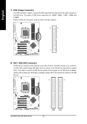
... set the jumper on one IDE cable, and the single IDE cable can connect to one IDE device as Slave (for information on settings, please refer to the instructions located on the IDE device). 40 39 GA-K8NS Ultra-939 Motherboard 2 IDE2 1 IDE1 - 24 - One IDE connector can then connect to two IDE devices (hard drive or optical drive). Please connect the red power connector wire to the pin1 position. 34 33 2 1 8) IDE1 / IDE2 (IDE Connector) An IDE device connects to the computer via an IDE connector. The types...
... set the jumper on one IDE cable, and the single IDE cable can connect to one IDE device as Slave (for information on settings, please refer to the instructions located on the IDE device). 40 39 GA-K8NS Ultra-939 Motherboard 2 IDE2 1 IDE1 - 24 - One IDE connector can then connect to two IDE devices (hard drive or optical drive). Please connect the red power connector wire to the pin1 position. 34 33 2 1 8) IDE1 / IDE2 (IDE Connector) An IDE device connects to the computer via an IDE connector. The types...
User Manual
Page 25
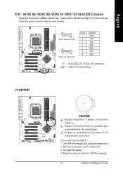
...'s instructions. Remove the battery, wait for the Serial ATA and install the proper driver in order to work properly. 1 7 SATA0_SB / SATA1_SB 7 1 SATA0_SII / SATA1_SII Pin No. 1 2 3 4 5 6 7 Definition GND TXP TXN GND RXN RXP GND The SATA0_SII / SATA1_SII connectors support hot plug function. 11) BATTERY CAUTION Danger of used batteries according to erase CMOS... 1. Replace only with the same or equivalent type recommended by the manufacturer. Re-install the battery. 4. Plug the power...
...'s instructions. Remove the battery, wait for the Serial ATA and install the proper driver in order to work properly. 1 7 SATA0_SB / SATA1_SB 7 1 SATA0_SII / SATA1_SII Pin No. 1 2 3 4 5 6 7 Definition GND TXP TXN GND RXN RXP GND The SATA0_SII / SATA1_SII connectors support hot plug function. 11) BATTERY CAUTION Danger of used batteries according to erase CMOS... 1. Replace only with the same or equivalent type recommended by the manufacturer. Re-install the battery. 4. Plug the power...

User Manual
Page 26
... LED/ Power/ Sleep LED SPEAK- 20 19 SPEAK+ PWPW+ MSGMSG+ 21 NCRES+ RES- HDHD+ Reset Switch IDE Hard Disk Active LED HD (IDE Hard Disk Active LED) (Blue) SPK (Speaker Connector) (Amber) RES (Reset Switch) (Green) PW (Power Switch) (Red) MSG (Message LED/ Power/ Sleep LED) (Yellow) NC (Purple) Pin 1: LED anode(+) Pin 2: LED cathode(-) Pin 1: VCC(+) Pin 2- Pin 3: NC Pin 4: Data(-) Open: Normal Operation Close: Reset Hardware System Open: Normal Operation Close: Power On/Off Pin 1: LED anode(+) Pin 2: LED cathode(-) NC GA-K8NS Ultra-939 Motherboard - 26 - of your chassis front panel...
... LED/ Power/ Sleep LED SPEAK- 20 19 SPEAK+ PWPW+ MSGMSG+ 21 NCRES+ RES- HDHD+ Reset Switch IDE Hard Disk Active LED HD (IDE Hard Disk Active LED) (Blue) SPK (Speaker Connector) (Amber) RES (Reset Switch) (Green) PW (Power Switch) (Red) MSG (Message LED/ Power/ Sleep LED) (Yellow) NC (Purple) Pin 1: LED anode(+) Pin 2: LED cathode(-) Pin 1: VCC(+) Pin 2- Pin 3: NC Pin 4: Data(-) Open: Normal Operation Close: Reset Hardware System Open: Normal Operation Close: Power On/Off Pin 1: LED anode(+) Pin 2: LED cathode(-) NC GA-K8NS Ultra-939 Motherboard - 26 - of your chassis front panel...
User Manual
Page 38
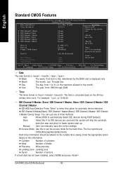
... settings Access Mode Use this option for faster system start up. Enter the appropriate option based on the 24-hour military-time clock. GA-K8NS Ultra-939 Motherboard - 38 - to select this to set the access mode for the hard drive. The time is , , , . is displayed only. Jan. IDE Channel 0 Master, Slave / IDE Channel 1 Master, Slave / IDE Channel 2 Master / IDE Channel 3 Master IDE HDD Auto-Detection Press "Enter" to Sat. IDE Channel 0 Master(Slave) / IDE Channel 1 Master(Slave) / IDE Channel 2 Master / IDE Channel 3 Master Device Setup. Manual User can use...
... settings Access Mode Use this option for faster system start up. Enter the appropriate option based on the 24-hour military-time clock. GA-K8NS Ultra-939 Motherboard - 38 - to select this to set the access mode for the hard drive. The time is , , , . is displayed only. Jan. IDE Channel 0 Master, Slave / IDE Channel 1 Master, Slave / IDE Channel 2 Master / IDE Channel 3 Master IDE HDD Auto-Detection Press "Enter" to Sat. IDE Channel 0 Master(Slave) / IDE Channel 1 Master(Slave) / IDE Channel 2 Master / IDE Channel 3 Master Device Setup. Manual User can use...
User Manual
Page 42
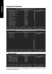
... Setup Utility-Copyright (C) 1984-2004 Award Software Integrated Peripherals IDE Function Setup On-Chip Primary PCI IDE On-Chip Secondary PCI IDE USB Host Controller USB Keyboard Support USB Mouse Support Serial-ATA 2(Internal PHY) AC97 Audio On-Chip LAN(nVIDIA) Onboard Serial ATA Serial ATA Function Onboard 1394 Onboard LAN Control Onboard LAN Boot ROM Onboard Serial Port 1 Onboard Serial Port 2 Onboard Parallel Port Parallel Port Mode x ECP Mode Use DMA [Press Enter] [Enabled] [Enabled] [V1.1+V2.0] [Disabled] [Disabled] [Enabled] [Auto] [Auto] [Enabled] [RAID] [Enabled] [Enabled] [Disabled...
... Setup Utility-Copyright (C) 1984-2004 Award Software Integrated Peripherals IDE Function Setup On-Chip Primary PCI IDE On-Chip Secondary PCI IDE USB Host Controller USB Keyboard Support USB Mouse Support Serial-ATA 2(Internal PHY) AC97 Audio On-Chip LAN(nVIDIA) Onboard Serial ATA Serial ATA Function Onboard 1394 Onboard LAN Control Onboard LAN Boot ROM Onboard Serial Port 1 Onboard Serial Port 2 Onboard Parallel Port Parallel Port Mode x ECP Mode Use DMA [Press Enter] [Enabled] [Enabled] [V1.1+V2.0] [Disabled] [Disabled] [Enabled] [Auto] [Auto] [Enabled] [RAID] [Enabled] [Enabled] [Disabled...
User Manual
Page 52
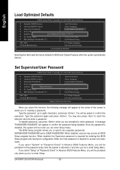
... the screen to enter Setup Menu. To disable password, just press when you to access only basic items. If you select "System" at "Password Check" in creating a password. Type the password again and press . Set Supervisor/User Password CMOS Setup Utility-Copyright (C) 1984-2004 Award Software ` Standard CMOS Features ` Advanced BIOS Features ` Integrated Peripherals ` Power Management Setup ` PnP/PCI ConfiguratioEnsnter Password: ` PC Health Status ` MB Intelligent Tweaker(M.I .T.) Exit Without Saving ESC: Quit F8: Dual BIOS/Q-Flash F3: Change Language...
... the screen to enter Setup Menu. To disable password, just press when you to access only basic items. If you select "System" at "Password Check" in creating a password. Type the password again and press . Set Supervisor/User Password CMOS Setup Utility-Copyright (C) 1984-2004 Award Software ` Standard CMOS Features ` Advanced BIOS Features ` Integrated Peripherals ` Power Management Setup ` PnP/PCI ConfiguratioEnsnter Password: ` PC Health Status ` MB Intelligent Tweaker(M.I .T.) Exit Without Saving ESC: Quit F8: Dual BIOS/Q-Flash F3: Change Language...
User Manual
Page 56
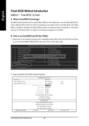
...-2004 Award Software ` Standard CMOS Features Select Language ` Advanced BIOS Features Load Fail-Safe Defaults ` Integrated Peripherals Load Optimized Defaults ` Power Management Setup Set Supervisor Password ` PnP/PCI Configurations Enter Dual BIOS/Q-Flash UtSileityU(sYer/NP)a?ssYword ` PC Health Status Save & Exit Setup ` MB Intelligent Tweaker(M.I.T.) Exit Without Saving ESC: Quit F8: Dual BIOS/Q-Flash F3: Change Language F10: Save & Exit Setup 2.) Award Dual BIOS Flash ROM Programming Utility Dual BIOS Utility V1.33 Boot From Main Bios Main ROM Type/Size SST 39SF040...
...-2004 Award Software ` Standard CMOS Features Select Language ` Advanced BIOS Features Load Fail-Safe Defaults ` Integrated Peripherals Load Optimized Defaults ` Power Management Setup Set Supervisor Password ` PnP/PCI Configurations Enter Dual BIOS/Q-Flash UtSileityU(sYer/NP)a?ssYword ` PC Health Status Save & Exit Setup ` MB Intelligent Tweaker(M.I.T.) Exit Without Saving ESC: Quit F8: Dual BIOS/Q-Flash F3: Change Language F10: Save & Exit Setup 2.) Award Dual BIOS Flash ROM Programming Utility Dual BIOS Utility V1.33 Boot From Main Bios Main ROM Type/Size SST 39SF040...
User Manual
Page 72
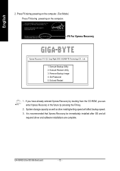
... For Xpress Recovery Xpress Recovery V1.0 (C) Copy Right 2003. System storage capacity as well as drive reading/writing speed will affect backup speed. 3. GA-K8NS Ultra-939 Motherboard - 72 - English 2. Intel 865PE AGPSet BIOS for 8IPE1000MT F1 Check System Health OK . . . GIGABYTE Technology CO. , Ltd. 1. Set Password 5. Exit and Restart 1. It is recommended that Xpress Recovery be immediately installed after OS and all required driver and software installations are complete. Remove Backup...
... For Xpress Recovery Xpress Recovery V1.0 (C) Copy Right 2003. System storage capacity as well as drive reading/writing speed will affect backup speed. 3. GA-K8NS Ultra-939 Motherboard - 72 - English 2. Intel 865PE AGPSet BIOS for 8IPE1000MT F1 Check System Health OK . . . GIGABYTE Technology CO. , Ltd. 1. Set Password 5. Exit and Restart 1. It is recommended that Xpress Recovery be immediately installed after OS and all required driver and software installations are complete. Remove Backup...
User Manual
Page 78
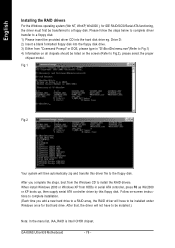
... this floppy disk. Please follow the steps below to complete driver transfer to Fig.2), please select the proper chipset model. GA-K8NS Ultra-939 Motherboard - 78 - When install Windows 2000 or Windows XP from "Command Prompt" or DOS, please type in serial ATA controller, press F6 as Win2000 or XP boots up, then supply serial ATA controller driver by this driver file to be transferred to install the RAID drivers. Drive D: 2) Insert a blank formatted floppy disk into the hard disk drive eg...
... this floppy disk. Please follow the steps below to complete driver transfer to Fig.2), please select the proper chipset model. GA-K8NS Ultra-939 Motherboard - 78 - When install Windows 2000 or Windows XP from "Command Prompt" or DOS, please type in serial ATA controller, press F6 as Win2000 or XP boots up, then supply serial ATA controller driver by this driver file to be transferred to install the RAID drivers. Drive D: 2) Insert a blank formatted floppy disk into the hard disk drive eg...
User Manual
Page 82
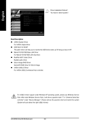
....0 driver support under "Device Manager". After install Windows Service Pack, it will auto-detect the right USB2.0 driver). Item Description „ nVIDIA System Driver For nVIDIA chipset driver. „ USB Patch for Silicon Image. „ nVIDIA USB 2.0 Driver For nVIDIA USB 2.0 enhanced host controller. GA-K8NS Ultra-939 Motherboard - 82 - in XP. „ Marvell 10/100/1000 Base LAN Driver For Marvell 10/100/1000 LAN chip driver. „ RealTek AC97 Codec Driver Realtek audio driver. „ Silicon Image RAID Driver Serial...
....0 driver support under "Device Manager". After install Windows Service Pack, it will auto-detect the right USB2.0 driver). Item Description „ nVIDIA System Driver For nVIDIA chipset driver. „ USB Patch for Silicon Image. „ nVIDIA USB 2.0 Driver For nVIDIA USB 2.0 enhanced host controller. GA-K8NS Ultra-939 Motherboard - 82 - in XP. „ Marvell 10/100/1000 Base LAN Driver For Marvell 10/100/1000 LAN chip driver. „ RealTek AC97 Codec Driver Realtek audio driver. „ Silicon Image RAID Driver Serial...
User Manual
Page 85
... to a floppy disk before installing drivers. Appendix Question 4: Why do I still get a weak sound after I fail to install RAID and ATA drivers under Win 2000 and XP on after updating BIOS. Question 7: Why do I connect the boot HDD to the maximum volume? Connect power cord to clear CMOS. Answer: The availability of my keyboard/optical mouse still on boards that were included in EasyTune 4, these options. If your board has a Clear CMOS jumper, please refer...
... to a floppy disk before installing drivers. Appendix Question 4: Why do I still get a weak sound after I fail to install RAID and ATA drivers under Win 2000 and XP on after updating BIOS. Question 7: Why do I connect the boot HDD to the maximum volume? Connect power cord to clear CMOS. Answer: The availability of my keyboard/optical mouse still on boards that were included in EasyTune 4, these options. If your board has a Clear CMOS jumper, please refer...
User Manual
Page 86
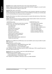
... which have connected any cable that you identify the possible computer problems. However, they are always fatal. 2 short: CMOS setting error 1 beep Refresh failure 1 long 1 short: DRAM or M/B error 2 beeps Parity error 1 long 2 short: Monitor or display card error 3 beeps Base 64K memory failure 1 long 3 short: Keyboard error 4 beeps Timer not operational 1 long 9 short: BIOS ROM error 5 beeps Processor error Continuous long beeps: DRAM error 6 beeps 8042 - English Question 8: How do I disable onboard VGA card in order to case. Answer: Gigabyte motherboards will auto-detect...
... which have connected any cable that you identify the possible computer problems. However, they are always fatal. 2 short: CMOS setting error 1 beep Refresh failure 1 long 1 short: DRAM or M/B error 2 beeps Parity error 1 long 2 short: Monitor or display card error 3 beeps Base 64K memory failure 1 long 3 short: Keyboard error 4 beeps Timer not operational 1 long 9 short: BIOS ROM error 5 beeps Processor error Continuous long beeps: DRAM error 6 beeps 8042 - English Question 8: How do I disable onboard VGA card in order to case. Answer: Gigabyte motherboards will auto-detect...
User Manual
Page 88
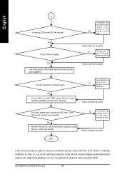
... is defective. Choose "Load Optimized Defaults" and save then exit setup. No The problem was probably caused by power supply, CPU, memory or CPU/ No memory socket itself. The appropriate response will be caused by the IDE device / connector or cable. GA-K8NS Ultra-939 Motherboard - 88 - Failure has been excluded. Check if the system can reboot successfully. Reboot after keyboard and mouse have been plugged in. Turn off the system. Failure has been excluded...
... is defective. Choose "Load Optimized Defaults" and save then exit setup. No The problem was probably caused by power supply, CPU, memory or CPU/ No memory socket itself. The appropriate response will be caused by the IDE device / connector or cable. GA-K8NS Ultra-939 Motherboard - 88 - Failure has been excluded. Check if the system can reboot successfully. Reboot after keyboard and mouse have been plugged in. Turn off the system. Failure has been excluded...


