
User Manual
Page 1
GA-K8N51PVMT-9-RH AMD Socket 939 Processor Motherboard User's Manual Rev. 1001 12ME-51PVMT9R-1001R * The WEEE marking on the product indicates this product must not be disposed of with user's other household waste and must be handed over to a designated collection point for the recycling of waste electrical and electronic equipment!! * The WEEE marking applies only in European Union's member states.
GA-K8N51PVMT-9-RH AMD Socket 939 Processor Motherboard User's Manual Rev. 1001 12ME-51PVMT9R-1001R * The WEEE marking on the product indicates this product must not be disposed of with user's other household waste and must be handed over to a designated collection point for the recycling of waste electrical and electronic equipment!! * The WEEE marking applies only in European Union's member states.
User Manual
Page 4
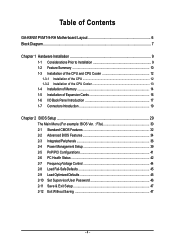
Table of Contents GA-K8N51PVMT-9-RH Motherboard Layout 6 Block Diagram ...7 Chapter 1 Hardware Installation 9 1-1 Considerations Prior to Installation 9 1-2 Feature Summary 10 1-3 Installation of the CPU and CPU Cooler 12 1-3-1 Installation of the CPU ...
Table of Contents GA-K8N51PVMT-9-RH Motherboard Layout 6 Block Diagram ...7 Chapter 1 Hardware Installation 9 1-1 Considerations Prior to Installation 9 1-2 Feature Summary 10 1-3 Installation of the CPU and CPU Cooler 12 1-3-1 Installation of the CPU ...
User Manual
Page 6
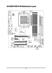
GA-K8N51PVMT-9-RH Motherboard Layout KB_MS ATX_12V Socket 939 CPU_FAN ATX FDD TV GA-K8N51PVMT-9-RH LPT VGA 1394 USB W83627 LAN USB AUDIO1 AUDIO2 F_AUDIO PCIE_16 nVIDIA® GeForce 6150 VITESSE PCIE_1 8201 CI CD_IN BIOS PCI1 PCI2 VIA VT6307 DDR1 DDR2 DDR3 DDR4 IDE2 BAT nVIDIA® nForce 430 CLR_CMOS CODEC COMA SPDIF_IO SYS_FAN F1_1394 F_USB1 F_USB2 F_PANEL1 PWR_LED IDE1 SATAII0_1 SATAII2_3 - 6 -
GA-K8N51PVMT-9-RH Motherboard Layout KB_MS ATX_12V Socket 939 CPU_FAN ATX FDD TV GA-K8N51PVMT-9-RH LPT VGA 1394 USB W83627 LAN USB AUDIO1 AUDIO2 F_AUDIO PCIE_16 nVIDIA® GeForce 6150 VITESSE PCIE_1 8201 CI CD_IN BIOS PCI1 PCI2 VIA VT6307 DDR1 DDR2 DDR3 DDR4 IDE2 BAT nVIDIA® nForce 430 CLR_CMOS CODEC COMA SPDIF_IO SYS_FAN F1_1394 F_USB1 F_USB2 F_PANEL1 PWR_LED IDE1 SATAII0_1 SATAII2_3 - 6 -
User Manual
Page 9
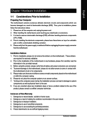
... or its power cord. 2. These stickers are no leftover screws or metal components placed on the motherboard or within a electrostatic shielding container. 5. Damage due to be an unofficial Gigabyte product. - 9 - Instances of an antistatic pad or within the computer casing. 6. Damage as ... validation. 2. Please verify that all cables and power connectors are uncertain about any installation steps or have these items on the motherboard. Damage due to use exceeding the permitted parameters. 6. Damage due to use of uncertified components. 5. Thus, prior to natural...
... or its power cord. 2. These stickers are no leftover screws or metal components placed on the motherboard or within a electrostatic shielding container. 5. Damage due to be an unofficial Gigabyte product. - 9 - Instances of an antistatic pad or within the computer casing. 6. Damage as ... validation. 2. Please verify that all cables and power connectors are uncertain about any installation steps or have these items on the motherboard. Damage due to use exceeding the permitted parameters. 6. Damage due to use of uncertified components. 5. Thus, prior to natural...
User Manual
Page 10
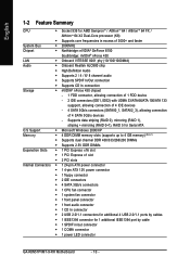
... / AlthlonTM 64 FX / AlthlonTM 64 X2 Dual-Core processor (K8) Š Supports core frequencies in /out connector Š 1 COMA connector Š 1 power LED connector GA-K8N51PVMT-9-RH Motherboard - 10 - English 1-2 Feature Summary CPU Š Socket 939 for 1 additional IEEE1394 port by cable Š 1 SPDIF in excess of 3000+ and faster System Bus Š...
... / AlthlonTM 64 FX / AlthlonTM 64 X2 Dual-Core processor (K8) Š Supports core frequencies in /out connector Š 1 COMA connector Š 1 power LED connector GA-K8N51PVMT-9-RH Motherboard - 10 - English 1-2 Feature Summary CPU Š Socket 939 for 1 additional IEEE1394 port by cable Š 1 SPDIF in excess of 3000+ and faster System Bus Š...

User Manual
Page 11
... Factor Š Micro ATX form factor; 24.4cm x 24.4cm (Note 1) Due to standard PC architecture, a certain amount of memory size will depend on different motherboards. - 11 - For more detailed information please check at the FAQ section on GIGABYTE's website. (Note 4) EasyTune functions may vary depending on the CPU you install.
... Factor Š Micro ATX form factor; 24.4cm x 24.4cm (Note 1) Due to standard PC architecture, a certain amount of memory size will depend on different motherboards. - 11 - For more detailed information please check at the FAQ section on GIGABYTE's website. (Note 4) EasyTune functions may vary depending on the CPU you install.
User Manual
Page 12
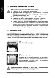
...original position. Please make sure the CPU cooler is positioned into place. Once the CPU is installed on the middle of the CPU. 3. GA-K8N51PVMT-9-RH Motherboard - 12 - If you wish to set beyond the proper specifications, please do so according to system use extra care when installing the CPU... CPU pins to the socket and gently lower it does not meet the required standards for the peripherals. Align the CPU to see that the motherboard supports the CPU. 2. If you install the CPU in Fig. 2. Please take note of the pin 1 marking (the small triangle) on...
...original position. Please make sure the CPU cooler is positioned into place. Once the CPU is installed on the middle of the CPU. 3. GA-K8N51PVMT-9-RH Motherboard - 12 - If you wish to set beyond the proper specifications, please do so according to system use extra care when installing the CPU... CPU pins to the socket and gently lower it does not meet the required standards for the peripherals. Align the CPU to see that the motherboard supports the CPU. 2. If you install the CPU in Fig. 2. Please take note of the pin 1 marking (the small triangle) on...
User Manual
Page 13
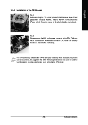
... - Hardware Installation English 1-3-2 Installation of the CPU Cooler Fig.1 Before installing the CPU cooler, please first add an even layer of heat paste on the motherboard so that either thermal tape rather than heat paste be used for detailed installation instructions).
... - Hardware Installation English 1-3-2 Installation of the CPU Cooler Fig.1 Before installing the CPU cooler, please first add an even layer of heat paste on the motherboard so that either thermal tape rather than heat paste be used for detailed installation instructions).
User Manual
Page 14
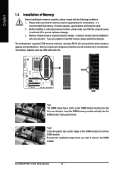
...memory used is switched off to lock the DIMM module. If you wish to insert the module, please switch the direction. GA-K8N51PVMT-9-RH Motherboard - 14 - Before installing or removing memory modules, please make sure that memory of Memory Before installing the memory modules, please... the DIMM memory module can be installed in one direction. Then push it down. Memory modules have a foolproof insertion design. The motherboard supports DDR memory modules, whereby BIOS will automatically detect memory capacity and specifications. Memory modules are unable to remove the DIMM module....
...memory used is switched off to lock the DIMM module. If you wish to insert the module, please switch the direction. GA-K8N51PVMT-9-RH Motherboard - 14 - Before installing or removing memory modules, please make sure that memory of Memory Before installing the memory modules, please... the DIMM memory module can be installed in one direction. Then push it down. Memory modules have a foolproof insertion design. The motherboard supports DDR memory modules, whereby BIOS will automatically detect memory capacity and specifications. Memory modules are unable to remove the DIMM module....
User Manual
Page 16
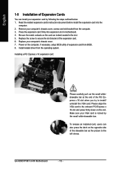
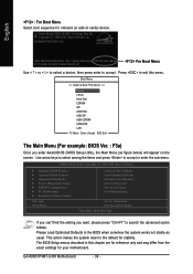
Power on the card are indeed seated in motherboard. 4. Press the expansion card firmly into the computer. 2. GA-K8N51PVMT-9-RH Motherboard - 16 - Read the related expansion card's instruction document before install the expansion card into expansion slot in the slot. 5. Be sure the metal contacts on ...
Power on the card are indeed seated in motherboard. 4. Press the expansion card firmly into the computer. 2. GA-K8N51PVMT-9-RH Motherboard - 16 - Read the related expansion card's instruction document before install the expansion card into expansion slot in the slot. 5. Be sure the metal contacts on ...
User Manual
Page 18
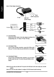
GA-K8N51PVMT-9-RH Motherboard - 18 - (Note 1) Video Adapter Introduction English TV Out Y Pr Pb/AV (HDTV Component) SVID OUT (S-Video Output) TV Out Port Video Adapter Pb/AV Pr Y S-...
GA-K8N51PVMT-9-RH Motherboard - 18 - (Note 1) Video Adapter Introduction English TV Out Y Pr Pb/AV (HDTV Component) SVID OUT (S-Video Output) TV Out Port Video Adapter Pb/AV Pr Y S-...

User Manual
Page 20
... 3.3V -12V GND PS_ON(soft On/Off) GND GND GND -5V +5V +5V +5V (Only for 24-pin ATX) GND(Only for 24-pin ATX) GA-K8N51PVMT-9-RH Motherboard - 20 - If a power supply is used (300W or greater). If you use a 24-pin ATX power supply, please remove the small cover on the... remove it. If the ATX_12V power connector is not connected, the system will not start . Align the power connector with its proper location on the motherboard before plugging in the power cord; Pin No. English 1/2) ATX_12V / ATX (Power Connector) With the use of the power connector, the power supply can lead...
... 3.3V -12V GND PS_ON(soft On/Off) GND GND GND -5V +5V +5V +5V (Only for 24-pin ATX) GND(Only for 24-pin ATX) GA-K8N51PVMT-9-RH Motherboard - 20 - If a power supply is used (300W or greater). If you use a 24-pin ATX power supply, please remove the small cover on the... remove it. If the ATX_12V power connector is not connected, the system will not start . Align the power connector with its proper location on the motherboard before plugging in the power cord; Pin No. English 1/2) ATX_12V / ATX (Power Connector) With the use of the power connector, the power supply can lead...

User Manual
Page 22
... an IDE connector. English 6) IDE1 / IDE2 (IDE Connector) An IDE device connects to work properly. 1 7 7 1 Pin No. 1 2 3 4 5 6 7 Definition GND TXP TXN GND RXN RXP GND GA-K8N51PVMT-9-RH Motherboard - 22 - One IDE connector can provide up to two IDE devices (hard drive or optical drive).
... an IDE connector. English 6) IDE1 / IDE2 (IDE Connector) An IDE device connects to work properly. 1 7 7 1 Pin No. 1 2 3 4 5 6 7 Definition GND TXP TXN GND RXN RXP GND GA-K8N51PVMT-9-RH Motherboard - 22 - One IDE connector can provide up to two IDE devices (hard drive or optical drive).

User Manual
Page 24
... Pin 2- Pin 3: NC Pin 4: Data(-) Open: Normal Close: Reset Hardware System Open: Normal Close: Power On/Off Pin 1: LED anode(+) Pin 2: LED cathode(-) NC GA-K8N51PVMT-9-RH Motherboard - 24 - English 10) F_PANEL (Front Panel Jumper) Please connect the power LED, PC speaker, reset switch and power switch etc. PW+ PWSPEAK+ SPEAK- 2 20 1 19...
... Pin 2- Pin 3: NC Pin 4: Data(-) Open: Normal Close: Reset Hardware System Open: Normal Close: Power On/Off Pin 1: LED anode(+) Pin 2: LED cathode(-) NC GA-K8N51PVMT-9-RH Motherboard - 24 - English 10) F_PANEL (Front Panel Jumper) Please connect the power LED, PC speaker, reset switch and power switch etc. PW+ PWSPEAK+ SPEAK- 2 20 1 19...
User Manual
Page 26
... to work or even damage it . Pin No. Definition 1 TPA+ 2 10 2 TPA- 1 9 3 GND 4 GND 5 TPB+ 6 TPB- 7 Power(12V) 8 Power(12V) 9 No Pin 10 GND GA-K8N51PVMT-9-RH Motherboard - 26 - English 13) F_ USB1 / F_USB2 (Front USB Connector) Be careful with the polarity of the IEEE1394 connector. For optional front USB cable, please contact...
... to work or even damage it . Pin No. Definition 1 TPA+ 2 10 2 TPA- 1 9 3 GND 4 GND 5 TPB+ 6 TPB- 7 Power(12V) 8 Power(12V) 9 No Pin 10 GND GA-K8N51PVMT-9-RH Motherboard - 26 - English 13) F_ USB1 / F_USB2 (Front USB Connector) Be careful with the polarity of the IEEE1394 connector. For optional front USB cable, please contact...

User Manual
Page 28
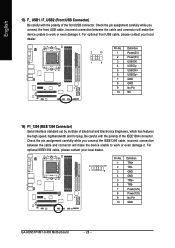
You can check the "Case Open" status in BIOS Setup. Default doesn't include the jumper to detect if the chassis cover is removed. Definition 1 1 Signal 2 GND GA-K8N51PVMT-9-RH Motherboard - 28 - To clear CMOS, temporarily short 1-2 pin. Pin No. English 17) CLR_CMOS (Clear CMOS) You may clear the CMOS data to its default values by this header. 1 Open: Normal 1 Short: Clear CMOS 18) CI (Chassis Intrusion, Case Open) This 2-pin connector allows your system to avoid improper use of this header.
You can check the "Case Open" status in BIOS Setup. Default doesn't include the jumper to detect if the chassis cover is removed. Definition 1 1 Signal 2 GND GA-K8N51PVMT-9-RH Motherboard - 28 - To clear CMOS, temporarily short 1-2 pin. Pin No. English 17) CLR_CMOS (Clear CMOS) You may clear the CMOS data to its default values by this header. 1 Open: Normal 1 Short: Clear CMOS 18) CI (Chassis Intrusion, Case Open) This 2-pin connector allows your system to avoid improper use of this header.
User Manual
Page 29
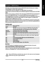
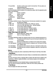
... first time, it with caution and avoid inadequate operation that BIOS needs to be used. Exit current page and return to a new BIOS, either Gigabyte's Q-Flash or @BIOS utility can enter the BIOS setup screen by pressing "Ctrl + F1". Because BIOS flashing is turned on, pushing the button...default table Load the Optimized Defaults Q-Flash utility System Information Save all the CMOS changes, only for Main Menu Main Menu The on the motherboard supplies the necessary power to its original settings. Status Page Setup Menu / Option Page Setup Menu Press to pop up BIOS for the highlighted...
... first time, it with caution and avoid inadequate operation that BIOS needs to be used. Exit current page and return to a new BIOS, either Gigabyte's Q-Flash or @BIOS utility can enter the BIOS setup screen by pressing "Ctrl + F1". Because BIOS flashing is turned on, pushing the button...default table Load the Optimized Defaults Q-Flash utility System Information Save all the CMOS changes, only for Main Menu Main Menu The on the motherboard supplies the necessary power to its original settings. Status Page Setup Menu / Option Page Setup Menu Press to pop up BIOS for the highlighted...
User Manual
Page 30
... Setup Time, Date, Hard Disk Type... Please Load Optimized Defaults in this menu. This action makes the system reset to search the advanced option hidden. GA-K8N51PVMT-9-RH Motherboard - 30 - Award Modular BIOS v6.00PG, An Energy Star Ally Copyright (C) 1984-2006, Award Software, Inc. Use arrow keys to select among the items...
... Setup Time, Date, Hard Disk Type... Please Load Optimized Defaults in this menu. This action makes the system reset to search the advanced option hidden. GA-K8N51PVMT-9-RH Motherboard - 30 - Award Modular BIOS v6.00PG, An Energy Star Ally Copyright (C) 1984-2006, Award Software, Inc. Use arrow keys to select among the items...

User Manual
Page 32
... detection. Through Dec. IDE Channel 1 Master/Slave IDE HDD Auto-Detection Press "Enter" to Sat. to select this option for the hard drive. For example, 1 p.m. GA-K8N51PVMT-9-RH Motherboard - 32 -
... detection. Through Dec. IDE Channel 1 Master/Slave IDE HDD Auto-Detection Press "Enter" to Sat. to select this option for the hard drive. For example, 1 p.m. GA-K8N51PVMT-9-RH Motherboard - 32 -
User Manual
Page 33
...is present during power up. Base Memory The POST of the BIOS will be prompted. Hard drive information should be labeled on the motherboard. The two options are: Large/Auto(default:Auto) Capacity Capacity of base (or conventional) memory installed in the CPU's memory ... double-sided drive; 1.44M byte capacity. 2.88M, 3.5" 3.5 inch double-sided drive; 2.88M byte capacity. Enter the appropriate option based on the motherboard, or 640K for any error that used. - 33 - All Errors Whenever the BIOS detects a non-fatal error the system will determine the amount ...
...is present during power up. Base Memory The POST of the BIOS will be prompted. Hard drive information should be labeled on the motherboard. The two options are: Large/Auto(default:Auto) Capacity Capacity of base (or conventional) memory installed in the CPU's memory ... double-sided drive; 1.44M byte capacity. 2.88M, 3.5" 3.5 inch double-sided drive; 2.88M byte capacity. Enter the appropriate option based on the motherboard, or 640K for any error that used. - 33 - All Errors Whenever the BIOS detects a non-fatal error the system will determine the amount ...


