
Manual
Page 1
.... (Note 3) If you manually build a non-RAID 0 array, you have to automatically set up a RAID 0 array. 2. B. eXtreme Hard Drive (X.H.D) With GIGABYTE eXtreme Hard Drive (X.H.D)(Note 1), users can go to the Application Software screen to enable RAID for the Intel SATA controllers. Step 2: Install the RAID driver...quickly set up a RAID-ready system and configure it for RAID 0. Setting Up a RAID-Ready System Step 1: Configure the system BIOS Enter the system BIOS Setup program, set up a RAID 0 array: Click Auto to automatically install all of your data to avoid risk of hardware damage...
.... (Note 3) If you manually build a non-RAID 0 array, you have to automatically set up a RAID 0 array. 2. B. eXtreme Hard Drive (X.H.D) With GIGABYTE eXtreme Hard Drive (X.H.D)(Note 1), users can go to the Application Software screen to enable RAID for the Intel SATA controllers. Step 2: Install the RAID driver...quickly set up a RAID-ready system and configure it for RAID 0. Setting Up a RAID-Ready System Step 1: Configure the system BIOS Enter the system BIOS Setup program, set up a RAID 0 array: Click Auto to automatically install all of your data to avoid risk of hardware damage...

Manual
Page 3
... features, read the User's Manual. For instructions on your motherboard revision before updating motherboard BIOS, drivers, or when looking for technical information. For product-related information, check on our website at: http://www.gigabyte.com.tw Identifying Your Motherboard Revision The revision number on how to the specifications and features in this...
... features, read the User's Manual. For instructions on your motherboard revision before updating motherboard BIOS, drivers, or when looking for technical information. For product-related information, check on our website at: http://www.gigabyte.com.tw Identifying Your Motherboard Revision The revision number on how to the specifications and features in this...
Manual
Page 4
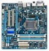
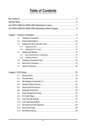
Table of Contents Box Contents...6 Optional Items...6 GA-H57M-USB3/GA-H55M-USB3 Motherboard Layout 7 GA-H57M-USB3/GA-H55M-USB3 Motherboard Block Diagram 8 Chapter 1 Hardware Installation 9 1-1 Installation Precautions 9 1-2 Product Specifications 10 1-3 Installing the CPU... Expansion Card 18 1-6 Back Panel Connectors 19 1-7 Internal Connectors 22 Chapter 2 BIOS Setup 33 2-1 Startup Screen 34 2-2 The Main Menu 35 2-3 MB Intelligent Tweaker(M.I.T 37 2-4 Standard CMOS Features 46 2-5 Advanced BIOS Features 48 2-6 Integrated Peripherals 50 2-7 Power Management Setup 53 2-8 PC Health ...
Table of Contents Box Contents...6 Optional Items...6 GA-H57M-USB3/GA-H55M-USB3 Motherboard Layout 7 GA-H57M-USB3/GA-H55M-USB3 Motherboard Block Diagram 8 Chapter 1 Hardware Installation 9 1-1 Installation Precautions 9 1-2 Product Specifications 10 1-3 Installing the CPU... Expansion Card 18 1-6 Back Panel Connectors 19 1-7 Internal Connectors 22 Chapter 2 BIOS Setup 33 2-1 Startup Screen 34 2-2 The Main Menu 35 2-3 MB Intelligent Tweaker(M.I.T 37 2-4 Standard CMOS Features 46 2-5 Advanced BIOS Features 48 2-6 Integrated Peripherals 50 2-7 Power Management Setup 53 2-8 PC Health ...
Manual
Page 5
... Utility 68 4-2-2 Updating the BIOS with the @BIOS Utility 71 4-3 EasyTune 6...72 4-4 Dynamic Energy Saver™ 2 73 4-5 Q-Share...75 4-6 Smart 6™ ...76 4-7 Auto Green...79 4-8 eXtreme Hard Drive (X.H.D) j 80 Chapter 5 Appendix...81 5-1 Configuring SATA Hard Drive(s 81 5-1-1 Configuring Intel H57 SATA Controllers j 81 5-1-2 Configuring GIGABYTE SATA2 SATA Controller 89 5-1-3 ... 112 5-2-5 Using the Sound Recorder 114 5-3 Troubleshooting 115 5-3-1 Frequently Asked Questions 115 5-3-2 Troubleshooting Procedure 116 5-4 Regulatory Statements 118 j Only for GA-H57M-USB3. - 5 -
... Utility 68 4-2-2 Updating the BIOS with the @BIOS Utility 71 4-3 EasyTune 6...72 4-4 Dynamic Energy Saver™ 2 73 4-5 Q-Share...75 4-6 Smart 6™ ...76 4-7 Auto Green...79 4-8 eXtreme Hard Drive (X.H.D) j 80 Chapter 5 Appendix...81 5-1 Configuring SATA Hard Drive(s 81 5-1-1 Configuring Intel H57 SATA Controllers j 81 5-1-2 Configuring GIGABYTE SATA2 SATA Controller 89 5-1-3 ... 112 5-2-5 Using the Sound Recorder 114 5-3 Troubleshooting 115 5-3-1 Frequently Asked Questions 115 5-3-2 Troubleshooting Procedure 116 5-4 Regulatory Statements 118 j Only for GA-H57M-USB3. - 5 -
Manual
Page 8
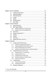
... for output when in the BIOS Setup program or when during the POST screens. (Note 2) Two share the same ports with USB 3.0. - 8 - DisplayPort, HDMI, and DVI-D) for GA-H55M-USB3. (Note 1) You can use only one of the onboard digital graphics ports (e.g. GA-H57M-USB3/GA-H55M-USB3 Motherboard Block Diagram 1 PCI ... X1 x1 x1 RTL8111D RJ45 GIGABYTE SATA2 Intel® H57 j Intel® H55 k 1 PCI Express x4 j 1 PCI Express x1 k PCI Bus LAN 2 SATA 3Gb/s ATA-133/100/66/33 IDE Channel TSB43AB23 2 IEEE 1394a CODEC DisplayPort, HDMI, or DVI-D (Note 1) D-Sub Dual BIOS 6 SATA 3Gb/s 14 USB...
... for output when in the BIOS Setup program or when during the POST screens. (Note 2) Two share the same ports with USB 3.0. - 8 - DisplayPort, HDMI, and DVI-D) for GA-H55M-USB3. (Note 1) You can use only one of the onboard digital graphics ports (e.g. GA-H57M-USB3/GA-H55M-USB3 Motherboard Block Diagram 1 PCI ... X1 x1 x1 RTL8111D RJ45 GIGABYTE SATA2 Intel® H57 j Intel® H55 k 1 PCI Express x4 j 1 PCI Express x1 k PCI Bus LAN 2 SATA 3Gb/s ATA-133/100/66/33 IDE Channel TSB43AB23 2 IEEE 1394a CODEC DisplayPort, HDMI, or DVI-D (Note 1) D-Sub Dual BIOS 6 SATA 3Gb/s 14 USB...
Manual
Page 12
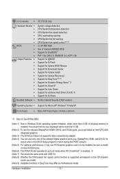
.... (Note 9) Available functions in EasyTune may differ by motherboard model. DisplayPort, HDMI, and DVI-D) for GA-H57M-USB3. (Note 1) Due to Windows 32-bit operating system limitation, when more than 4 GB. (Note ... 8) Whether the CPU/system fan speed control function is enabled. Hardware Installation - 12 - I/O Controller w Hardware Monitor w w w w w w BIOS w w w w Unique Features w w w w w w w w w w w w Bundled Software w iTE IT8720 chip System voltage detection CPU...
.... (Note 9) Available functions in EasyTune may differ by motherboard model. DisplayPort, HDMI, and DVI-D) for GA-H57M-USB3. (Note 1) Due to Windows 32-bit operating system limitation, when more than 4 GB. (Note ... 8) Whether the CPU/system fan speed control function is enabled. Hardware Installation - 12 - I/O Controller w Hardware Monitor w w w w w w BIOS w w w w Unique Features w w w w w w w w w w w w Bundled Software w iTE IT8720 chip System voltage detection CPU...
Manual
Page 16
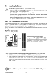
...DS/SS DS/SS DDR3_3 DS/SS DS/SS (SS=Single-Sided, DS=Double-Sided, "- -"=No Memory) DDR3_2 DDR3_1 DDR3_4 DDR3_3 Due to GIGABYTE's website for optimum performance. DS/SS - - Hardware Installation - 16 - When enabling Dual Channel mode with two or four memory modules, ...: Channel 0: DDR3_2, DDR2_1 Channel 1: DDR3_4, DDR3_3 Dual Channel Memory Configurations Table DDR3_2 DDR3_1 DDR3_4 Two Modules - - It is installed, the BIOS will double the original memory bandwidth. If you begin to install it is recommended that memory of the memory. A memory module can be sure...
...DS/SS DS/SS DDR3_3 DS/SS DS/SS (SS=Single-Sided, DS=Double-Sided, "- -"=No Memory) DDR3_2 DDR3_1 DDR3_4 DDR3_3 Due to GIGABYTE's website for optimum performance. DS/SS - - Hardware Installation - 16 - When enabling Dual Channel mode with two or four memory modules, ...: Channel 0: DDR3_2, DDR2_1 Channel 1: DDR3_4, DDR3_3 Dual Channel Memory Configurations Table DDR3_2 DDR3_1 DDR3_4 Two Modules - - It is installed, the BIOS will double the original memory bandwidth. If you begin to install it is recommended that memory of the memory. A memory module can be sure...

Manual
Page 18
... slot. 1. After installing all expansion cards, replace the chassis cover(s). 6. Locate an expansion slot that came with a screw. 5. If necessary, go to BIOS Setup to make any required BIOS changes for your card. Hardware Installation - 18 - 1-5 Installing an Expansion Card Read the following guidelines before installing an expansion card to prevent hardware...
... slot. 1. After installing all expansion cards, replace the chassis cover(s). 6. Locate an expansion slot that came with a screw. 5. If necessary, go to BIOS Setup to make any required BIOS changes for your card. Hardware Installation - 18 - 1-5 Installing an Expansion Card Read the following guidelines before installing an expansion card to prevent hardware...
Manual
Page 20
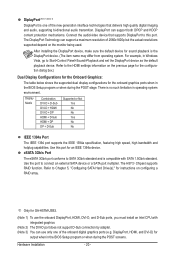
... on the monitor being used. Refer to this port for an IEEE 1394a device. There is no such limitation in the BIOS Setup program or when during the POST screens. The DisplayPort Technology can support both DPCP and HDCP content protection mechanisms. Connect...IEEE 1394a specification, featuring high speed, high bandwidth and hotplug capabilities. After installing the DisplayPort device, make sure the default device for GA-H57M-USB3. (Note 1) To use only one of the new generation interface technologies that supports DisplayPort to the HDMI settings information on configuring a ...
... on the monitor being used. Refer to this port for an IEEE 1394a device. There is no such limitation in the BIOS Setup program or when during the POST screens. The DisplayPort Technology can support both DPCP and HDCP content protection mechanisms. Connect...IEEE 1394a specification, featuring high speed, high bandwidth and hotplug capabilities. After installing the DisplayPort device, make sure the default device for GA-H57M-USB3. (Note 1) To use only one of the new generation interface technologies that supports DisplayPort to the HDMI settings information on configuring a ...

Manual
Page 26
The GIGABYTE SATA2 controller supports RAID 0 and RAID 1. You may be lost. Hardware Installation - 26 - Gently remove the battery from the battery holder and wait for one . ... be used, the total number of purchase or local dealer if you are not able to replace the battery by GIGABYTE SATA2) The SATA connectors conform to keep the values (such as BIOS configurations, date, and time information) in the power cord and restart your computer. • Always turn off . If more...
The GIGABYTE SATA2 controller supports RAID 0 and RAID 1. You may be lost. Hardware Installation - 26 - Gently remove the battery from the battery holder and wait for one . ... be used, the total number of purchase or local dealer if you are not able to replace the battery by GIGABYTE SATA2) The SATA connectors conform to keep the values (such as BIOS configurations, date, and time information) in the power cord and restart your computer. • Always turn off . If more...

Manual
Page 27
... different patterns to the hard drive activity LED on the chassis front panel. When connecting your system using the power switch (refer to Chapter 2, "BIOS Setup," "Power Management Setup," for information about beep codes. • HD (Hard Drive Activity LED, Blue) Connects to indicate the problem. The... chassis with a chassis intrusion switch/sensor. The front panel design may differ by issuing a beep code. The LED S0 On is detected, the BIOS may configure the way to turn off (S5). • PW (Power Switch, Red): Connects to the power switch on when the system is ...
... different patterns to the hard drive activity LED on the chassis front panel. When connecting your system using the power switch (refer to Chapter 2, "BIOS Setup," "Power Management Setup," for information about beep codes. • HD (Hard Drive Activity LED, Blue) Connects to indicate the problem. The... chassis with a chassis intrusion switch/sensor. The front panel design may differ by issuing a beep code. The LED S0 On is detected, the BIOS may configure the way to turn off (S5). • PW (Power Switch, Red): Connects to the power switch on when the system is ...

Manual
Page 31
...to do so may cause damage to the motherboard. • After system restart, go to BIOS Setup to load factory defaults (select Load Optimized Defaults) or manually configure the BIOS settings (refer to touch the two pins for BIOS configurations). - 31 - 18) COMA (Serial Port Header) The COMA header can provide ...the CMOS values and before turning on the two pins to temporarily short the two pins or use a metal object like a screwdriver to Chapter 2, "BIOS Setup," for a few seconds. To clear the CMOS values, place a jumper cap on your computer and unplug the power cord from the jumper.
...to do so may cause damage to the motherboard. • After system restart, go to BIOS Setup to load factory defaults (select Load Optimized Defaults) or manually configure the BIOS settings (refer to touch the two pins for BIOS configurations). - 31 - 18) COMA (Serial Port Header) The COMA header can provide ...the CMOS values and before turning on the two pins to temporarily short the two pins or use a metal object like a screwdriver to Chapter 2, "BIOS Setup," for a few seconds. To clear the CMOS values, place a jumper cap on your computer and unplug the power cord from the jumper.

Manual
Page 33
...CMOS on using the Q-Flash and @BIOS utilities, refer to Chapter 4, "BIOS Update Utilities." • Because BIOS flashing is a Windows-based utility that you need to) to clear the CMOS values.) - 33 - To upgrade the BIOS, use either the GIGABYTE Q-Flash or @BIOS utility. • Q-Flash allows ...the user to activate certain system features. Inadequate BIOS flashing may result in system's failure to keep the configuration values in the main...
...CMOS on using the Q-Flash and @BIOS utilities, refer to Chapter 4, "BIOS Update Utilities." • Because BIOS flashing is a Windows-based utility that you need to) to clear the CMOS values.) - 33 - To upgrade the BIOS, use either the GIGABYTE Q-Flash or @BIOS utility. • Q-Flash allows ...the user to activate certain system features. Inadequate BIOS flashing may result in system's failure to keep the configuration values in the main...
Manual
Page 34
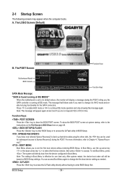
..., use the up hard drive data using the driver disk, the key can access Boot Menu again to change it to enter BIOS Setup first. A. Motherboard Model BIOS Version H55M/H57M-USB3 E8 . . . . : BIOS Setup : XpressRecovery2 : Boot Menu : Qflash 12/22/2009-H55/H57-7A89TG0PC-00 Function Keys Function Keys SATA Mode Message: "SATA is...
..., use the up hard drive data using the driver disk, the key can access Boot Menu again to change it to enter BIOS Setup first. A. Motherboard Model BIOS Version H55M/H57M-USB3 E8 . . . . : BIOS Setup : XpressRecovery2 : Boot Menu : Qflash 12/22/2009-H55/H57-7A89TG0PC-00 Function Keys Function Keys SATA Mode Message: "SATA is...

Manual
Page 35
...on the screen. Press to exit the help screen (General Help) of the Main Menu. Submenu Help While in a submenu, press to BIOS Load CMOS from BIOS BIOS Setup Program Function Keys Move the selection bar to select an item Execute command or enter the submenu Main Menu: Exit the... bottom line of function keys available for the current submenus Access the Q-Flash utility Display system information Save all the changes and exit the BIOS Setup program Save CMOS to display a help screen. Use arrow keys to move among the items and press to accept or enter a ...
...on the screen. Press to exit the help screen (General Help) of the Main Menu. Submenu Help While in a submenu, press to BIOS Load CMOS from BIOS BIOS Setup Program Function Keys Move the selection bar to select an item Execute command or enter the submenu Main Menu: Exit the... bottom line of function keys available for the current submenus Access the Q-Flash utility Display system information Save all the changes and exit the BIOS Setup program Save CMOS to display a help screen. Use arrow keys to move among the items and press to accept or enter a ...

Manual
Page 36
...factory settings for optimal-performance system operations. Set Supervisor Password Change, set , or disable password. Pressing to the confirmation message will exit BIOS Setup. (Pressing can use the SPACE key) and then press to complete. F12: Load CMOS from a profile created before, without... Health Status Use this menu to configure the clock, frequency and voltages of errors that stop the system boot, etc. Advanced BIOS Features Use this menu to configure the device boot order, advanced features available on the CPU, and the primary display adapter. ...
...factory settings for optimal-performance system operations. Set Supervisor Password Change, set , or disable password. Pressing to the confirmation message will exit BIOS Setup. (Pressing can use the SPACE key) and then press to complete. F12: Load CMOS from a profile created before, without... Health Status Use this menu to configure the clock, frequency and voltages of errors that stop the system boot, etc. Advanced BIOS Features Use this menu to configure the device boot order, advanced features available on the CPU, and the primary display adapter. ...

Manual
Page 37
... Voltage Settings } Miscellaneous Settings [Press Enter] [Press Enter] [Press Enter] [Press Enter] [Press Enter] Item Help Menu Level BIOS Version BCLK CPU Frequency Memory Frequency Total Memory Size E8 133.37 MHz 3067.78 MHz 1333.75 MHz 1024 MB CPU Temperature PCH Temperature... Help F7: Optimized Defaults (Note 1) This item is present only if you install a CPU that supports this feature. BIOS Setup 2-3 MB Intelligent Tweaker(M.I.T.) CMOS Setup Utility-Copyright (C) 1984-2009 Award Software MB Intelligent Tweaker(M.I.T.) } M.I .T.
... Voltage Settings } Miscellaneous Settings [Press Enter] [Press Enter] [Press Enter] [Press Enter] [Press Enter] Item Help Menu Level BIOS Version BCLK CPU Frequency Memory Frequency Total Memory Size E8 133.37 MHz 3067.78 MHz 1333.75 MHz 1024 MB CPU Temperature PCH Temperature... Help F7: Optimized Defaults (Note 1) This item is present only if you install a CPU that supports this feature. BIOS Setup 2-3 MB Intelligent Tweaker(M.I.T.) CMOS Setup Utility-Copyright (C) 1984-2009 Award Software MB Intelligent Tweaker(M.I.T.) } M.I .T.
Manual
Page 38
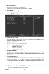
... Enhanced Halt (C1E) (Note) Enables or disables Intel CPU Enhanced Halt (C1E) function, a CPU power-saving function in system halt state. Auto lets the BIOS automatically configure this setting. (Default: Auto) CPU Cores Enabled (Note) Allows you to determine whether to enable all CPU cores. (Default) 1 Enables only one...2009 Award Software Advanced CPU Core Features Intel(R) Turbo Boost Tech. This feature only works for the installed CPU. All Enables all CPU cores. BIOS Setup - 38 - CPU Clock Ratio (Note) Allows you install a CPU that supports this feature. Auto lets the...
... Enhanced Halt (C1E) (Note) Enables or disables Intel CPU Enhanced Halt (C1E) function, a CPU power-saving function in system halt state. Auto lets the BIOS automatically configure this setting. (Default: Auto) CPU Cores Enabled (Note) Allows you to determine whether to enable all CPU cores. (Default) 1 Enables only one...2009 Award Software Advanced CPU Core Features Intel(R) Turbo Boost Tech. This feature only works for the installed CPU. All Enables all CPU cores. BIOS Setup - 38 - CPU Clock Ratio (Note) Allows you install a CPU that supports this feature. Auto lets the...

Manual
Page 39
...accordance with unlocked clock ratio is occurring to detect whether an overheating is installed. Enabled will be configurable. Auto lets the BIOS automatically configure this setting. (Default: Auto) CPU Thermal Monitor (Note) Enables or disables Intel CPU Thermal Monitor function,... a CPU overheating protection function. Auto lets the BIOS automatically configure this setting. (Default: Auto) CPU EIST Function (Note) Enables or disables Enhanced Intel SpeedStep Technology (EIST). When...
...accordance with unlocked clock ratio is occurring to detect whether an overheating is installed. Enabled will be configurable. Auto lets the BIOS automatically configure this setting. (Default: Auto) CPU Thermal Monitor (Note) Enables or disables Intel CPU Thermal Monitor function,... a CPU overheating protection function. Auto lets the BIOS automatically configure this setting. (Default: Auto) CPU EIST Function (Note) Enables or disables Enhanced Intel SpeedStep Technology (EIST). When...

Manual
Page 40
...~750ps. (Default: 0ps) (Note) This item appears only if you to adjust the amplitude of the PCI Express and Chipset clock. BIOS Setup - 40 - Extreme Memory Profile (X.M.P.) (Note) Allows the BIOS to read the SPD data on XMP memory module(s) to the CPU clock. Disabled Disables this feature. PCI Express Clock Drive...
...~750ps. (Default: 0ps) (Note) This item appears only if you to adjust the amplitude of the PCI Express and Chipset clock. BIOS Setup - 40 - Extreme Memory Profile (X.M.P.) (Note) Allows the BIOS to read the SPD data on XMP memory module(s) to the CPU clock. Disabled Disables this feature. PCI Express Clock Drive...


