
Manual
Page 1
...a RAID 0 array that before you can go to the Application Software screen to enhance your needs and hardware components. 3. Using GIGABYTE eXtreme Hard Drive (X.H.D) Instructions:(Note 2) Before launching X.H.D, make sure the newly added harddrive has equal or greater capacity than or equal...damage or lost of a button, X.H.D helps to individually install the X.H.D utility later. All with which you run the X.H.D utility, back up all motherboard drivers, including the X.H.D utility. To automatically set up a RAID 0 array: Click Auto to exit the X.H.D utility. (Note 1) The X.H.D ...
...a RAID 0 array that before you can go to the Application Software screen to enhance your needs and hardware components. 3. Using GIGABYTE eXtreme Hard Drive (X.H.D) Instructions:(Note 2) Before launching X.H.D, make sure the newly added harddrive has equal or greater capacity than or equal...damage or lost of a button, X.H.D helps to individually install the X.H.D utility later. All with which you run the X.H.D utility, back up all motherboard drivers, including the X.H.D utility. To automatically set up a RAID 0 array: Click Auto to exit the X.H.D utility. (Note 1) The X.H.D ...
Manual
Page 1
GA-H57M-USB3 GA-H55M-USB3 LGA1156 socket motherboard for Intel® Core™ i7 processor family/ Intel® Core™ i5 processor family/ Intel® Core™ i3 processor family User's Manual Rev. 1001 12ME-H57MUB3-1001R
GA-H57M-USB3 GA-H55M-USB3 LGA1156 socket motherboard for Intel® Core™ i7 processor family/ Intel® Core™ i5 processor family/ Intel® Core™ i3 processor family User's Manual Rev. 1001 12ME-H57MUB3-1001R
Manual
Page 2
Motherboard GA-H57M-USB3/GA-H55M-USB3 Jan. 14, 2010 Motherboard GA-H57M-USB3/ GA-H55M-USB3 Jan. 14, 2010
Motherboard GA-H57M-USB3/GA-H55M-USB3 Jan. 14, 2010 Motherboard GA-H57M-USB3/ GA-H55M-USB3 Jan. 14, 2010

Manual
Page 3
... product information, carefully read or download the information on/from the Support&Downloads\Motherboard\Technology Guide page on our website. Changes to use of this product, GIGABYTE provides the following types of documentations: For quick set-up of this manual ..., or published in this manual are legally registered to assist in the use GIGABYTE's unique features, read the User's Manual. Example: For instructions on your motherboard revision before updating motherboard BIOS, drivers, or when looking for technical information. For product-related information,...
... product information, carefully read or download the information on/from the Support&Downloads\Motherboard\Technology Guide page on our website. Changes to use of this product, GIGABYTE provides the following types of documentations: For quick set-up of this manual ..., or published in this manual are legally registered to assist in the use GIGABYTE's unique features, read the User's Manual. Example: For instructions on your motherboard revision before updating motherboard BIOS, drivers, or when looking for technical information. For product-related information,...
Manual
Page 4
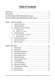
Table of Contents Box Contents...6 Optional Items...6 GA-H57M-USB3/GA-H55M-USB3 Motherboard Layout 7 GA-H57M-USB3/GA-H55M-USB3 Motherboard Block Diagram 8 Chapter 1 Hardware Installation 9 1-1 Installation Precautions 9 1-2 Product Specifications 10 1-3 Installing the CPU and CPU Cooler 13 1-3-1 Installing the CPU 13 1-3-2 Installing the CPU Cooler ...
Table of Contents Box Contents...6 Optional Items...6 GA-H57M-USB3/GA-H55M-USB3 Motherboard Layout 7 GA-H57M-USB3/GA-H55M-USB3 Motherboard Block Diagram 8 Chapter 1 Hardware Installation 9 1-1 Installation Precautions 9 1-2 Product Specifications 10 1-3 Installing the CPU and CPU Cooler 13 1-3-1 Installing the CPU 13 1-3-2 Installing the CPU Cooler ...
Manual
Page 6
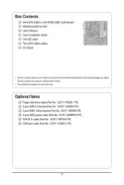
...-0*R) 2-port SATA power cable (Part No. 12CF1-2SERPW-0*R) S/PDIF In cable (Part No. 12CR1-1SPDIN-0*R) COM port cable (Part No. 12CF1-1CM001-3*R) - 6 - Box Contents GA-H57M-USB3 or GA-H55M-USB3 motherboard Motherboard driver disk User's Manual Quick Installation Guide One IDE cable Two SATA 3Gb/s cables I/O Shield • The box contents above are subject to change...
...-0*R) 2-port SATA power cable (Part No. 12CF1-2SERPW-0*R) S/PDIF In cable (Part No. 12CR1-1SPDIN-0*R) COM port cable (Part No. 12CF1-1CM001-3*R) - 6 - Box Contents GA-H57M-USB3 or GA-H55M-USB3 motherboard Motherboard driver disk User's Manual Quick Installation Guide One IDE cable Two SATA 3Gb/s cables I/O Shield • The box contents above are subject to change...
Manual
Page 7
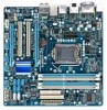
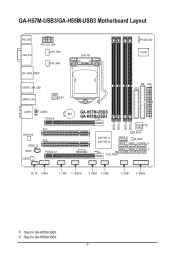
k Only for GA-H57M-USB3. GA-H57M-USB3/GA-H55M-USB3 Motherboard Layout KB_USB VGA_DVI ATX_12V_2X4 CPU_FAN SYS_FAN DP_HDMI_SPDIF ESATA_1394_USB USB30_LAN NEC D720200F1 LGA1156 PHASE LED IT8720 IDE ATX FDD AUDIO F_AUDIO PCIEX16 RTL8111D SPDIF_O SPDIF_I CODEC PCI1 PCI2 PCIEX4_X1 BAT GA-H57M-USB3/ GA-H55M-USB3 DDR3_2 DDR3_1 DDR3_4 DDR3_3 TSB43AB23 Intel® H57 j Intel® H55 k GIGABYTE SATA2 B_BIOS SATA2_0 M_BIOS SATA2_1 SATA2_3 GSATA2_6 SATA2_2 SATA2_4 GSATA2_5 CLR_CMOS CD_IN COMA F_1394 F_USB4j F_USB3 F_USB2 F_USB1 F_PANEL j Only for GA-H55M-USB3. - 7 -
k Only for GA-H57M-USB3. GA-H57M-USB3/GA-H55M-USB3 Motherboard Layout KB_USB VGA_DVI ATX_12V_2X4 CPU_FAN SYS_FAN DP_HDMI_SPDIF ESATA_1394_USB USB30_LAN NEC D720200F1 LGA1156 PHASE LED IT8720 IDE ATX FDD AUDIO F_AUDIO PCIEX16 RTL8111D SPDIF_O SPDIF_I CODEC PCI1 PCI2 PCIEX4_X1 BAT GA-H57M-USB3/ GA-H55M-USB3 DDR3_2 DDR3_1 DDR3_4 DDR3_3 TSB43AB23 Intel® H57 j Intel® H55 k GIGABYTE SATA2 B_BIOS SATA2_0 M_BIOS SATA2_1 SATA2_3 GSATA2_6 SATA2_2 SATA2_4 GSATA2_5 CLR_CMOS CD_IN COMA F_1394 F_USB4j F_USB3 F_USB2 F_USB1 F_PANEL j Only for GA-H55M-USB3. - 7 -
Manual
Page 8
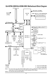
... 3.0. - 8 - GA-H57M-USB3/GA-H55M-USB3 Motherboard Block Diagram 1 PCI Express x16 CPU CLK+/- (133 MHz) PCIe CLK (100 MHz) LGA1156 CPU DDR3 1666 (O.C.)/1333/1066/800 MHz Dual Channel Memory DMI Interface FDI Interface x16 PCI Express Bus x1 Gen 2 2 USB 3.0 Switch PCI Express Bus x1 Gen 1 NEC D720200F1 x4/ X1 x1 x1 RTL8111D RJ45 GIGABYTE... Speaker Out Center/Subwoofer Speaker Out Side Speaker Out MIC Line Out Line In S/PDIF In S/PDIF Out 2 PCI PCI CLK (33 MHz) j Only for GA-H57M-USB3.
... 3.0. - 8 - GA-H57M-USB3/GA-H55M-USB3 Motherboard Block Diagram 1 PCI Express x16 CPU CLK+/- (133 MHz) PCIe CLK (100 MHz) LGA1156 CPU DDR3 1666 (O.C.)/1333/1066/800 MHz Dual Channel Memory DMI Interface FDI Interface x16 PCI Express Bus x1 Gen 2 2 USB 3.0 Switch PCI Express Bus x1 Gen 1 NEC D720200F1 x4/ X1 x1 x1 RTL8111D RJ45 GIGABYTE... Speaker Out Center/Subwoofer Speaker Out Side Speaker Out MIC Line Out Line In S/PDIF In S/PDIF Out 2 PCI PCI CLK (33 MHz) j Only for GA-H57M-USB3.
Manual
Page 9
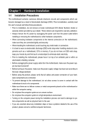
...system on an uneven surface. • Do not place the computer system in a high-temperature environment. • Turning on the motherboard, make sure the power supply voltage has been set according to the local voltage standard. • Before using the product, please... is best to wear an electrostatic discharge (ESD) wrist strap when handling electronic com- Chapter 1 Hardware Installation 1-1 Installation Precautions The motherboard contains numerous delicate electronic circuits and components which can become damaged as a result of your hardware components are connected. • To ...
...system on an uneven surface. • Do not place the computer system in a high-temperature environment. • Turning on the motherboard, make sure the power supply voltage has been set according to the local voltage standard. • Before using the product, please... is best to wear an electrostatic discharge (ESD) wrist strap when handling electronic com- Chapter 1 Hardware Installation 1-1 Installation Precautions The motherboard contains numerous delicate electronic circuits and components which can become damaged as a result of your hardware components are connected. • To ...
Manual
Page 12
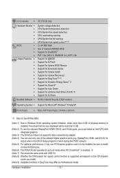
... function is enabled. Hardware Installation - 12 - DisplayPort, HDMI, and DVI-D) for GA-H57M-USB3. (Note 1) Due to x4 mode when ATI CrossFireX™ is supported will depend on the CPU/system cooler you install. (Note 9) Available functions in EasyTune may differ by motherboard model. I/O Controller w Hardware Monitor w w w w w w BIOS w w w w Unique Features w w w w w w w w w w w w Bundled Software w iTE IT8720...
... function is enabled. Hardware Installation - 12 - DisplayPort, HDMI, and DVI-D) for GA-H57M-USB3. (Note 1) Due to x4 mode when ATI CrossFireX™ is supported will depend on the CPU/system cooler you install. (Note 9) Available functions in EasyTune may differ by motherboard model. I/O Controller w Hardware Monitor w w w w w w BIOS w w w w Unique Features w w w w w w w w w w w w Bundled Software w iTE IT8720...

Manual
Page 13
...dam- If you may occur. • Set the CPU host frequency in accordance with the CPU specifications. Locate the alignment keys on the motherboard CPU socket and the notches on the CPU - 13 - 1-3 Installing the CPU and CPU Cooler Read the following guidelines before installing the ... including the CPU, graphics card, memory, hard drive, etc. 1-3-1 Installing the CPU A. It is not recommended that the motherboard supports the CPU. (Go to GIGABYTE's website for the peripherals. Hardware Installation age of the CPU may locate the notches on both sides of the CPU and alignment...
...dam- If you may occur. • Set the CPU host frequency in accordance with the CPU specifications. Locate the alignment keys on the motherboard CPU socket and the notches on the CPU - 13 - 1-3 Installing the CPU and CPU Cooler Read the following guidelines before installing the ... including the CPU, graphics card, memory, hard drive, etc. 1-3-1 Installing the CPU A. It is not recommended that the motherboard supports the CPU. (Go to GIGABYTE's website for the peripherals. Hardware Installation age of the CPU may locate the notches on both sides of the CPU and alignment...

Manual
Page 14
... CPU socket, always replace the protective socket cover when the CPU is under the shoulder screw. Step 5: Push the CPU socket lever back into the motherboard CPU socket. Hardware Installation - 14 - Before installing the CPU, make sure the front end of the load plate is not installed.) Step 3: Hold the CPU...
... CPU socket, always replace the protective socket cover when the CPU is under the shoulder screw. Step 5: Push the CPU socket lever back into the motherboard CPU socket. Hardware Installation - 14 - Before installing the CPU, make sure the front end of the load plate is not installed.) Step 3: Hold the CPU...

Manual
Page 15
... an even and thin layer of thermal grease on the surface of the CPU cooler to the CPU fan header (CPU_FAN) on the motherboard. Inadequately removing the CPU cooler may adhere to the CPU. Hardware Installation 1-3-2 Installing the CPU Cooler Follow the steps below to correctly ...install the CPU cooler on the motherboard. (The following procedure uses Intel® boxed cooler as the picture above shows, the installation is to install.) Step 3: Place the...
... an even and thin layer of thermal grease on the surface of the CPU cooler to the CPU fan header (CPU_FAN) on the motherboard. Inadequately removing the CPU cooler may adhere to the CPU. Hardware Installation 1-3-2 Installing the CPU Cooler Follow the steps below to correctly ...install the CPU cooler on the motherboard. (The following procedure uses Intel® boxed cooler as the picture above shows, the installation is to install.) Step 3: Place the...
Manual
Page 16
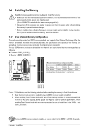
... will double the original memory bandwidth. If you begin to insert the memory, switch the direction. 1-4-1 Dual Channel Memory Configuration This motherboard provides four DDR3 memory sockets and supports Dual Channel Technology. When enabling Dual Channel mode with two or four memory modules, it in...latest memory support list.) • Always turn off the computer and unplug the power cord from the power outlet before installing the memory to GIGABYTE's website for optimum performance. It is recommended that memory of the same capacity, brand, speed, and chips be used . (Go to...
... will double the original memory bandwidth. If you begin to insert the memory, switch the direction. 1-4-1 Dual Channel Memory Configuration This motherboard provides four DDR3 memory sockets and supports Dual Channel Technology. When enabling Dual Channel mode with two or four memory modules, it in...latest memory support list.) • Always turn off the computer and unplug the power cord from the power outlet before installing the memory to GIGABYTE's website for optimum performance. It is recommended that memory of the same capacity, brand, speed, and chips be used . (Go to...
Manual
Page 17
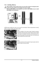
..., make sure to turn off the computer and unplug the power cord from the power outlet to prevent damage to install DDR3 DIMMs on this motherboard. Place the memory module on the memory and insert it can only fit in the memory sockets. Spread the retaining clips at both ends of...
..., make sure to turn off the computer and unplug the power cord from the power outlet to prevent damage to install DDR3 DIMMs on this motherboard. Place the memory module on the memory and insert it can only fit in the memory sockets. Spread the retaining clips at both ends of...

Manual
Page 18
... card. Carefully read the manual that supports your operating system. If necessary, go to BIOS Setup to install an expansion card: • Make sure the motherboard supports the expansion card. Align the card with your expansion card in the slot and does not rock. • Removing the Card: Press the white...
... card. Carefully read the manual that supports your operating system. If necessary, go to BIOS Setup to install an expansion card: • Make sure the motherboard supports the expansion card. Align the card with your expansion card in the slot and does not rock. • Removing the Card: Press the white...

Manual
Page 21
... drive and etc. This jack can be connected to a back panel connector, first remove the cable from your device and then remove it from the motherboard. • When removing the cable, pull it side to side to 1 Gbps data rate. Only microphones still MUST be reconfigured to connect rear speakers in...
... drive and etc. This jack can be connected to a back panel connector, first remove the cable from your device and then remove it from the motherboard. • When removing the cable, pull it side to side to 1 Gbps data rate. Only microphones still MUST be reconfigured to connect rear speakers in...
Manual
Page 22
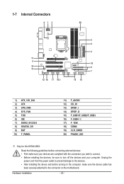
Read the following guidelines before turning on the motherboard. Unplug the power cord from the power outlet to prevent damage to the devices. • After installing the device and before connecting external devices: • ...) F_PANEL 11) F_AUDIO 12) CD_IN 13) SPDIF_I 14) SPDIF_O 15) F_USB1/F_USB2/F_USB3 16) F_USB4 j 17) F_1394 18) COMA 19) CLR_CMOS 20) PHASE_LED j Only for GA-H57M-USB3. Hardware Installation - 22 -
Read the following guidelines before turning on the motherboard. Unplug the power cord from the power outlet to prevent damage to the devices. • After installing the device and before connecting external devices: • ...) F_PANEL 11) F_AUDIO 12) CD_IN 13) SPDIF_I 14) SPDIF_O 15) F_USB1/F_USB2/F_USB3 16) F_USB4 j 17) F_1394 18) COMA 19) CLR_CMOS 20) PHASE_LED j Only for GA-H57M-USB3. Hardware Installation - 22 -

Manual
Page 23
... all devices are properly installed. Before connecting the power connector, first make sure the power supply is turned off and all the components on the motherboard. If a power supply is used that can supply enough stable power to an unstable or unbootable system. 5 8 1 4 ATX_12V_2X4 ATX_12V_2X4: Pin No. The 12V power connector...
... all devices are properly installed. Before connecting the power connector, first make sure the power supply is turned off and all the components on the motherboard. If a power supply is used that can supply enough stable power to an unstable or unbootable system. 5 8 1 4 ATX_12V_2X4 ATX_12V_2X4: Pin No. The 12V power connector...

Manual
Page 24
... No. For purchasing the optional floppy disk drive cable, please contact the local dealer. 34 33 Hardware Installation 2 1 - 24 - 3/4) CPU_FAN/SYS_FAN (Fan Headers) The motherboard has a 4-pin CPU fan header (CPU_FAN) and a 4-pin (SYS_FAN). When connecting a fan cable, be sure to connect a floppy disk drive. Overheating may result in... This connector is typically designated by a stripe of a CPU fan with fan speed control design. Most fan headers possess a foolproof insertion design. The motherboard supports CPU fan speed control, which requires the use of different color.
... No. For purchasing the optional floppy disk drive cable, please contact the local dealer. 34 33 Hardware Installation 2 1 - 24 - 3/4) CPU_FAN/SYS_FAN (Fan Headers) The motherboard has a 4-pin CPU fan header (CPU_FAN) and a 4-pin (SYS_FAN). When connecting a fan cable, be sure to connect a floppy disk drive. Overheating may result in... This connector is typically designated by a stripe of a CPU fan with fan speed control design. Most fan headers possess a foolproof insertion design. The motherboard supports CPU fan speed control, which requires the use of different color.


