
Manual
Page 4
... Items...6 GA-H55N-USB3 Motherboard Layout 7 GA-H55N-USB3 Motherboard Block Diagram 8 Chapter 1 Hardware Installation 9 1-1 Installation Precautions 9 1-2 Product Specifications 10 1-3 Installing the CPU and CPU Cooler 13 1-3-1 Installing the CPU 13 1-3-2 Installing the CPU Cooler 15 1-4 Installing the Memory 16 1-4-1 Dual Channel Memory Configuration 16 1-4-2 Installing a Memory 17 1-5 Installing an Expansion Card 18 1-6 Back Panel Connectors 19...
... Items...6 GA-H55N-USB3 Motherboard Layout 7 GA-H55N-USB3 Motherboard Block Diagram 8 Chapter 1 Hardware Installation 9 1-1 Installation Precautions 9 1-2 Product Specifications 10 1-3 Installing the CPU and CPU Cooler 13 1-3-1 Installing the CPU 13 1-3-2 Installing the CPU Cooler 15 1-4 Installing the Memory 16 1-4-1 Dual Channel Memory Configuration 16 1-4-2 Installing a Memory 17 1-5 Installing an Expansion Card 18 1-6 Back Panel Connectors 19...

Manual
Page 10
... Chipset: - 4 x SATA 3Gb/s connectors supporting up to 4 SATA 3Gb/s devices - 1 x eSATA 3Gb/s connector on the back panel supporting up to 8 GB of system memory (Note 1) Dual channel memory architecture Support for DDR3 1666 (O.C.)/1333/1066/800 MHz memory modules Support for ...non-ECC memory modules Support for Extreme Memory Profile (XMP) memory modules (Go to GIGABYTE's website for the latest CPU support list.) L3 cache varies with CPU Chipset Intel® H55 Express Chipset Memory Onboard ...
... Chipset: - 4 x SATA 3Gb/s connectors supporting up to 4 SATA 3Gb/s devices - 1 x eSATA 3Gb/s connector on the back panel supporting up to 8 GB of system memory (Note 1) Dual channel memory architecture Support for DDR3 1666 (O.C.)/1333/1066/800 MHz memory modules Support for ...non-ECC memory modules Support for Extreme Memory Profile (XMP) memory modules (Go to GIGABYTE's website for the latest CPU support list.) L3 cache varies with CPU Chipset Intel® H55 Express Chipset Memory Onboard ...

Manual
Page 11
... w w w w w w w w w 1 x 24-pin ATX main power connector 1 x 4-pin ATX 12V power connector 4 x SATA 3Gb/s connectors 1 x CPU fan header 1 x system fan header 1 x front panel header 1 x front panel audio header 1 x S/PDIF Out header 2 x USB 2.0/1.1 headers 1 x debug card header 1 x chassis intrusion header 1 x clearing CMOS jumper 1 x PS/2 keyboard/mouse port 1 x D-Sub port (Note 2) 1 x DVI-D port (...
... w w w w w w w w w 1 x 24-pin ATX main power connector 1 x 4-pin ATX 12V power connector 4 x SATA 3Gb/s connectors 1 x CPU fan header 1 x system fan header 1 x front panel header 1 x front panel audio header 1 x S/PDIF Out header 2 x USB 2.0/1.1 headers 1 x debug card header 1 x chassis intrusion header 1 x clearing CMOS jumper 1 x PS/2 keyboard/mouse port 1 x D-Sub port (Note 2) 1 x DVI-D port (...

Manual
Page 18
... your expansion card. • Always turn off the computer and unplug the power cord from the power outlet before you begin to the chassis back panel with the expansion card in the slot and does not rock. • Removing the Card: Press the white latch at the end of the card... contacts on the top edge of the PCI Express slot to release the card and then pull the card straight up from the chassis back panel. 2. 1-5 Installing an Expansion Card Read the following guidelines before installing an expansion card to correctly install your operating system.
... your expansion card. • Always turn off the computer and unplug the power cord from the power outlet before you begin to the chassis back panel with the expansion card in the slot and does not rock. • Removing the Card: Press the white latch at the end of the card... contacts on the top edge of the PCI Express slot to release the card and then pull the card straight up from the chassis back panel. 2. 1-5 Installing an Expansion Card Read the following guidelines before installing an expansion card to correctly install your operating system.

Manual
Page 19
...monitor being used . • After installing the HDMI device, make sure the default device for decoding.) In Windows Vista, select Start>Control Panel>Sound> Playback, set Intel(R) Display Audio HDMI 2 to this port. Connect a monitor that supports digital optical audio. Optical S/PDIF Out ...LPCM formats. (AC3 and DTS require the use of 1920x1200 but the actual resolutions supported depend on the monitor being used ). 1-6 Back Panel Connectors USB 2.0/1.1 Port The USB port supports the USB 2.0/1.1 specification. Use this port to the figures below for USB devices such as ...
...monitor being used . • After installing the HDMI device, make sure the default device for decoding.) In Windows Vista, select Start>Control Panel>Sound> Playback, set Intel(R) Display Audio HDMI 2 to this port. Connect a monitor that supports digital optical audio. Optical S/PDIF Out ...LPCM formats. (AC3 and DTS require the use of 1920x1200 but the actual resolutions supported depend on the monitor being used ). 1-6 Back Panel Connectors USB 2.0/1.1 Port The USB port supports the USB 2.0/1.1 specification. Use this port to the figures below for USB devices such as ...

Manual
Page 21
... motherboard. • When removing the cable, pull it side to side to connect front speakers in jack ( ). Only microphones still MUST be reconfigured to a back panel connector, first remove the cable from your device and then remove it from the connector. Refer to the instructions on setting up a 2/4/5.1/7.1-channel audio configuration...
... motherboard. • When removing the cable, pull it side to side to connect front speakers in jack ( ). Only microphones still MUST be reconfigured to a back panel connector, first remove the cable from your device and then remove it from the connector. Refer to the instructions on setting up a 2/4/5.1/7.1-channel audio configuration...

Manual
Page 25
... chassis. Press the reset switch to restart the computer if the computer freezes and fails to the hard drive activity LED on the chassis front panel. Hardware Installation HD+ 9 1 10 2 PWPW+ MSGMSG+ • MSG (Message/Sleep LED, Yellow): Power Message/Sleep Switch LED System Status LED Connects to the... drive is in S3/S4 sleep S3/S4/S5 Off state or powered off your chassis front panel module to this header according to the power status indicator on the chassis front panel. The front panel design may configure the way to turn off (S5). • PW (Power Switch, Red): ...
... chassis. Press the reset switch to restart the computer if the computer freezes and fails to the hard drive activity LED on the chassis front panel. Hardware Installation HD+ 9 1 10 2 PWPW+ MSGMSG+ • MSG (Message/Sleep LED, Yellow): Power Message/Sleep Switch LED System Status LED Connects to the... drive is in S3/S4 sleep S3/S4/S5 Off state or powered off your chassis front panel module to this header according to the power status indicator on the chassis front panel. The front panel design may configure the way to turn off (S5). • PW (Power Switch, Red): ...

Manual
Page 26
...2x5-pin) cable into the USB header. • Prior to work or even damage it. For information about connecting the front panel audio module that has separated connectors on both of a single plug. For purchasing the optional USB bracket, please contact the local ... pin assignments of the motherboard header. Incorrect connection between the module connector and the motherboard header will be sure to turn off your chassis front panel audio module to activate AC'97 functionality via an optional USB bracket. Definition 1 2 1 MIC2_L 1 MIC 2 GND 2 GND 9 10 3 MIC2_R 3 MIC Power...
...2x5-pin) cable into the USB header. • Prior to work or even damage it. For information about connecting the front panel audio module that has separated connectors on both of a single plug. For purchasing the optional USB bracket, please contact the local ... pin assignments of the motherboard header. Incorrect connection between the module connector and the motherboard header will be sure to turn off your chassis front panel audio module to activate AC'97 functionality via an optional USB bracket. Definition 1 2 1 MIC2_L 1 MIC 2 GND 2 GND 9 10 3 MIC2_R 3 MIC Power...
Manual
Page 77
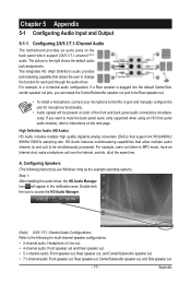
... speaker out jack to be Rear speaker out. • To install a microphone, connect your microphone to instructions on the back panel which support 2/4/5.1/7.1-channel (Note) audio. all at the same time. HD Audio features multistreaming capabilities that allows the user to be... present on both of the front and back panel audio connections simultaneously. Appendix The integrated HD (High Definition) audio provides jack retasking capability that allow multiple audio streams (in and...
... speaker out jack to be Rear speaker out. • To install a microphone, connect your microphone to instructions on the back panel which support 2/4/5.1/7.1-channel (Note) audio. all at the same time. HD Audio features multistreaming capabilities that allows the user to be... present on both of the front and back panel audio connections simultaneously. Appendix The integrated HD (High Definition) audio provides jack retasking capability that allow multiple audio streams (in and...

Manual
Page 78
...The The current connected device is completed. Configuring Sound Effect You may configure an audio environment on the Speaker Configuration tab. Muting the Back Panel Audio (For HD Audio Only) Click Device advanced settings on the top right corner on the Speaker Configuration tab to an audio jack. ...Appendix - 78 - Then click OK. B. On the Connector Settings dialog box, select the Disable front panel jack detection check box. C. Click OK to activate the AC'97 functionality, click the tool icon on the Sound Effects tab. Select the Mute...
...The The current connected device is completed. Configuring Sound Effect You may configure an audio environment on the Speaker Configuration tab. Muting the Back Panel Audio (For HD Audio Only) Click Device advanced settings on the top right corner on the Speaker Configuration tab to an audio jack. ...Appendix - 78 - Then click OK. B. On the Connector Settings dialog box, select the Disable front panel jack detection check box. C. Click OK to activate the AC'97 functionality, click the tool icon on the Sound Effects tab. Select the Mute...

Manual
Page 79
... may differ by model. (Note 2) Enter the Digital Output(Optical) screen to configure further settings if you use the S/PDIF Out connector on the back panel for digital audio output or enter the Digital Output screen if you use the internal S/PDIF Out connector (SPDIF_O) for decoding to an external decoder...
... may differ by model. (Note 2) Enter the Digital Output(Optical) screen to configure further settings if you use the S/PDIF Out connector on the back panel for digital audio output or enter the Digital Output screen if you use the internal S/PDIF Out connector (SPDIF_O) for decoding to an external decoder...

Manual
Page 80
Step 2: Connect your microphone to the Mic in jack (pink) on the back panel or the Mic in the notification area. Step 3: Go to record the sound. To hear the sound being recorded during the recording process, do not ... you set the volumes at the same time. Appendix - 80 - Double-click the icon to microphone, right-click on the front panel. Note: The microphone functions on the front panel and back panel cannot be able to the Microphone screen. It is recommended that you 'll not be used at a middle level. 5-1-3 Configuring...
Step 2: Connect your microphone to the Mic in jack (pink) on the back panel or the Mic in the notification area. Step 3: Go to record the sound. To hear the sound being recorded during the recording process, do not ... you set the volumes at the same time. Appendix - 80 - Double-click the icon to microphone, right-click on the front panel. Note: The microphone functions on the front panel and back panel cannot be able to the Microphone screen. It is recommended that you 'll not be used at a middle level. 5-1-3 Configuring...


