Manual
Page 1
GA-G41MT-ES2L LGA775 socket motherboard for Intel® Core™ processor family/ Intel® Pentium® processor family/Intel® Celeron® processor family User's Manual Rev. 1101 12ME-G41MT2L-1101R
GA-G41MT-ES2L LGA775 socket motherboard for Intel® Core™ processor family/ Intel® Pentium® processor family/Intel® Celeron® processor family User's Manual Rev. 1101 12ME-G41MT2L-1101R
Manual
Page 2
Motherboard GA-G41MT-ES2L Oct. 23, 2009 Motherboard GA-G41MT-ES2L Oct. 23, 2009
Motherboard GA-G41MT-ES2L Oct. 23, 2009 Motherboard GA-G41MT-ES2L Oct. 23, 2009
Manual
Page 3
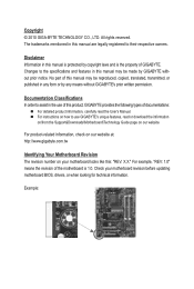
... order to use of this manual may be made by GIGABYTE without GIGABYTE's prior written permission. Example: Disclaimer Information in this product, GIGABYTE provides the following types of GIGABYTE. For product-related information, check on our website at: http://www.gigabyte.com.tw Identifying Your Motherboard Revision The revision number on how to assist in any...
... order to use of this manual may be made by GIGABYTE without GIGABYTE's prior written permission. Example: Disclaimer Information in this product, GIGABYTE provides the following types of GIGABYTE. For product-related information, check on our website at: http://www.gigabyte.com.tw Identifying Your Motherboard Revision The revision number on how to assist in any...
Manual
Page 4
Table of Contents Box Contents...6 Optional Items...6 GA-G41MT-ES2L Motherboard Layout 7 Block Diagram...8 Chapter 1 Hardware Installation 9 1-1 Installation Precautions 9 1-2 Product Specifications 10 1-3 Installing the CPU and CPU Cooler 13 1-3-1 Installing the CPU 13 1-3-2 Installing the CPU ...
Table of Contents Box Contents...6 Optional Items...6 GA-G41MT-ES2L Motherboard Layout 7 Block Diagram...8 Chapter 1 Hardware Installation 9 1-1 Installation Precautions 9 1-2 Product Specifications 10 1-3 Installing the CPU and CPU Cooler 13 1-3-1 Installing the CPU 13 1-3-2 Installing the CPU ...
Manual
Page 6
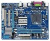
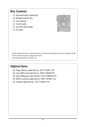
Box Contents GA-G41MT-ES2L motherboard Motherboard driver disk User's Manual One IDE cable Two SATA 3Gb/s cables I/O Shield • The box contents above are subject to change without notice. • The motherboard image is for reference only and the actual items shall depend on the product package you obtain. The box contents are for reference only...
Box Contents GA-G41MT-ES2L motherboard Motherboard driver disk User's Manual One IDE cable Two SATA 3Gb/s cables I/O Shield • The box contents above are subject to change without notice. • The motherboard image is for reference only and the actual items shall depend on the product package you obtain. The box contents are for reference only...
Manual
Page 7
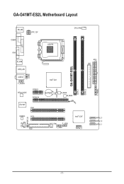
GA-G41MT-ES2L Motherboard Layout CLR_CMOS GA-G41MT-ES2L DDR3_1 DDR3_2 F_PANEL KB_MS COMA ATX_12V LGA775 CPU_FAN LPT COMB VGA R_USB USB_LAN AUDIO F_AUDIO RTL8111D/E PCIEX1 PCIEX16 IT8718F PCI1 Intel® G41 BATTERY B_BIOS M_BIOS ATX IDE CODEC PCI2 CD_IN SPDIF_IO FDD SYS_FAN F_USB2 F_USB1 Intel® ICH7 SATA2_0 SATA2_3 SATA2_2 SATA2_1 - 7 -
GA-G41MT-ES2L Motherboard Layout CLR_CMOS GA-G41MT-ES2L DDR3_1 DDR3_2 F_PANEL KB_MS COMA ATX_12V LGA775 CPU_FAN LPT COMB VGA R_USB USB_LAN AUDIO F_AUDIO RTL8111D/E PCIEX1 PCIEX16 IT8718F PCI1 Intel® G41 BATTERY B_BIOS M_BIOS ATX IDE CODEC PCI2 CD_IN SPDIF_IO FDD SYS_FAN F_USB2 F_USB1 Intel® ICH7 SATA2_0 SATA2_3 SATA2_2 SATA2_1 - 7 -
Manual
Page 9
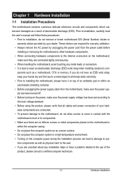
...not have an ESD wrist strap, keep your dealer. Hardware Installation These stickers are connected tightly and securely. • When handling the motherboard, avoid touching any installation steps or have it on top of an antistatic pad or within an electrostatic shielding container. • Before unplugging... all cables and power connectors of your hardware components are connected. • To prevent damage to the motherboard, do not allow screws to come in contact with the motherboard circuit or its components. • Make sure there are no leftover screws or metal components placed on ...
...not have an ESD wrist strap, keep your dealer. Hardware Installation These stickers are connected tightly and securely. • When handling the motherboard, avoid touching any installation steps or have it on top of an antistatic pad or within an electrostatic shielding container. • Before unplugging... all cables and power connectors of your hardware components are connected. • To prevent damage to the motherboard, do not allow screws to come in contact with the motherboard circuit or its components. • Make sure there are no leftover screws or metal components placed on ...
Manual
Page 12
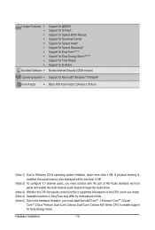
... 3) Whether the CPU fan speed control function is supported will depend on the CPU cooler you install. (Note 4) Available functions in EasyTune may differ by motherboard model. (Note 5) Due to the hardware limitation, you must install the Intel®CoreTM 2 Extreme/ CoreTM 2 Quad/ CoreTM 2 Duo/ Pentium Dual-Core/ Celeron Dual-Core...
... 3) Whether the CPU fan speed control function is supported will depend on the CPU cooler you install. (Note 4) Available functions in EasyTune may differ by motherboard model. (Note 5) Due to the hardware limitation, you must install the Intel®CoreTM 2 Extreme/ CoreTM 2 Quad/ CoreTM 2 Duo/ Pentium Dual-Core/ Celeron Dual-Core...
Manual
Page 13
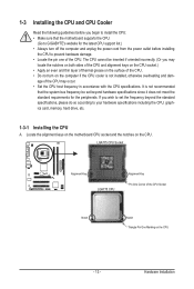
... - It is not installed, otherwise overheating and dam- Locate the alignment keys on the motherboard CPU socket and the notches on the computer if the CPU cooler is not recommended that the motherboard supports the CPU. (Go to GIGABYTE's website for the peripherals. age of the CPU. LGA775 CPU Socket Alignment Key LGA775...
... - It is not installed, otherwise overheating and dam- Locate the alignment keys on the motherboard CPU socket and the notches on the computer if the CPU cooler is not recommended that the motherboard supports the CPU. (Go to GIGABYTE's website for the peripherals. age of the CPU. LGA775 CPU Socket Alignment Key LGA775...
Manual
Page 14
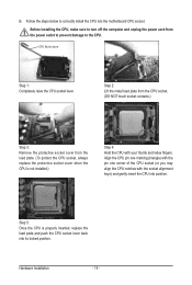
... index fingers. Step 5: Once the CPU is not installed.) Step 4: Hold the CPU with the socket alignment keys) and gently insert the CPU into the motherboard CPU socket. Hardware Installation - 14 - Step 2: Lift the metal load plate from the CPU socket. (DO NOT touch socket contacts.) Step 3: Remove the protective socket...
... index fingers. Step 5: Once the CPU is not installed.) Step 4: Hold the CPU with the socket alignment keys) and gently insert the CPU into the motherboard CPU socket. Hardware Installation - 14 - Step 2: Lift the metal load plate from the CPU socket. (DO NOT touch socket contacts.) Step 3: Remove the protective socket...
Manual
Page 15
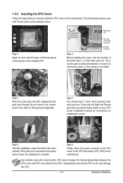
...on the contrary, is complete. Step 6: Finally, attach the power connector of the CPU cooler to correctly install the CPU cooler on the motherboard. (The following procedure uses Intel® boxed cooler as the picture above shows, the installation is to your CPU cooler installation manual for ... the back of the installed CPU. 1-3-2 Installing the CPU Cooler Follow the steps below to the CPU fan header (CPU_FAN) on the motherboard. Inadequately removing the CPU cooler may adhere to the CPU. Use extreme care when removing the CPU cooler because the thermal grease/tape between...
...on the contrary, is complete. Step 6: Finally, attach the power connector of the CPU cooler to correctly install the CPU cooler on the motherboard. (The following procedure uses Intel® boxed cooler as the picture above shows, the installation is to your CPU cooler installation manual for ... the back of the installed CPU. 1-3-2 Installing the CPU Cooler Follow the steps below to the CPU fan header (CPU_FAN) on the motherboard. Inadequately removing the CPU cooler may adhere to the CPU. Use extreme care when removing the CPU cooler because the thermal grease/tape between...
Manual
Page 16
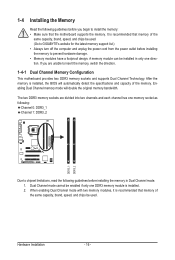
...of the same capacity, brand, speed, and chips be enabled if only one direction. Dual Channel mode cannot be used . (Go to GIGABYTE's website for the latest memory support list.) • Always turn off the computer and unplug the power cord from the power outlet before ...- 16 - When enabling Dual Channel mode with two memory modules, it is recommended that memory of the memory. It is recommended that the motherboard supports the memory. 1-4 Installing the Memory Read the following guidelines before you are divided into two channels and each channel has one memory socket ...
...of the same capacity, brand, speed, and chips be enabled if only one direction. Dual Channel mode cannot be used . (Go to GIGABYTE's website for the latest memory support list.) • Always turn off the computer and unplug the power cord from the power outlet before ...- 16 - When enabling Dual Channel mode with two memory modules, it is recommended that memory of the memory. It is recommended that the motherboard supports the memory. 1-4 Installing the Memory Read the following guidelines before you are divided into two channels and each channel has one memory socket ...
Manual
Page 17
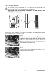
... ends of the memory, push down on the top edge of the memory socket. As indicated in one direction. Place the memory module on this motherboard. Follow the steps below to the memory module. 1-4-2 Installing a Memory Before installing a memory module, make sure to turn off the computer and unplug the power...
... ends of the memory, push down on the top edge of the memory socket. As indicated in one direction. Place the memory module on this motherboard. Follow the steps below to the memory module. 1-4-2 Installing a Memory Before installing a memory module, make sure to turn off the computer and unplug the power...
Manual
Page 18
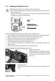
... turn off the computer and unplug the power cord from the power outlet before you begin to install an expansion card: • Make sure the motherboard supports the expansion card. Example: Installing and Removing a PCI Express Graphics Card: • Installing a Graphics Card: Gently push down on the card until it is...
... turn off the computer and unplug the power cord from the power outlet before you begin to install an expansion card: • Make sure the motherboard supports the expansion card. Example: Installing and Removing a PCI Express Graphics Card: • Installing a Graphics Card: Gently push down on the card until it is...
Manual
Page 19
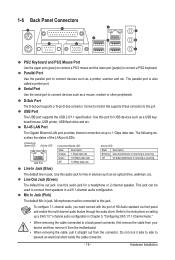
... and etc. Parallel Port Use the parallel port to a back panel connector, first remove the cable from your device and then remove it from the motherboard. • When removing the cable, pull it side to side to this port. Connect a monitor that supports D-Sub connection to this jack.
... and etc. Parallel Port Use the parallel port to a back panel connector, first remove the cable from your device and then remove it from the motherboard. • When removing the cable, pull it side to side to this port. Connect a monitor that supports D-Sub connection to this jack.
Manual
Page 20
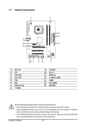
... 6) IDE 7) SATA2_0/1/2/3 8) F_PANEL 9) 10) 11) 12) 13) 14) 15) F_AUDIO CD_IN SPDIF_IO F_USB1/F_USB2 COMB CLR_CMOS BATTERY Read the following guidelines before turning on the motherboard. Unplug the power cord from the power outlet to prevent damage to the devices. • After installing the device and before connecting external devices: •...
... 6) IDE 7) SATA2_0/1/2/3 8) F_PANEL 9) 10) 11) 12) 13) 14) 15) F_AUDIO CD_IN SPDIF_IO F_USB1/F_USB2 COMB CLR_CMOS BATTERY Read the following guidelines before turning on the motherboard. Unplug the power cord from the power outlet to prevent damage to the devices. • After installing the device and before connecting external devices: •...
Manual
Page 21
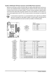
The power connector possesses a foolproof design. If a power supply is turned off and all the components on the motherboard. Before connecting the power connector, first make sure the power supply is used that can lead to an unstable or unbootable system. 3 4 1 2 ATX_12V ATX_12V: Pin ...
The power connector possesses a foolproof design. If a power supply is turned off and all the components on the motherboard. Before connecting the power connector, first make sure the power supply is used that can lead to an unstable or unbootable system. 3 4 1 2 ATX_12V ATX_12V: Pin ...
Manual
Page 22
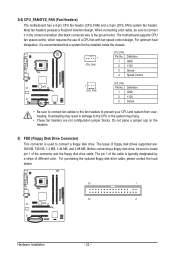
The motherboard supports CPU fan speed control, which requires the use of floppy disk drives supported are not configuration jumper blocks. The types of a CPU fan with .... 33 1 34 2 Hardware Installation - 22 - The pin 1 of the cable is used to prevent your CPU and system from overheating. 3/4) CPU_FAN/SYS_FAN (Fan Headers) The motherboard has a 4-pin CPU fan header (CPU_FAN) and a 3-pin (SYS_FAN) system fan header.
The motherboard supports CPU fan speed control, which requires the use of floppy disk drives supported are not configuration jumper blocks. The types of a CPU fan with .... 33 1 34 2 Hardware Installation - 22 - The pin 1 of the cable is used to prevent your CPU and system from overheating. 3/4) CPU_FAN/SYS_FAN (Fan Headers) The motherboard has a 4-pin CPU fan header (CPU_FAN) and a 3-pin (SYS_FAN) system fan header.
Manual
Page 25
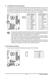
... 9 Line Out (L) 10 GND 10 NC • The front panel audio header supports HD audio by default. Incorrect connection between the module connector and the motherboard header will be present on both of the front and back panel audio connections simultaneously. Definition 2 10 1 MIC2_L Pin No. For information about connecting the... the audio software in Chapter 5, "Configuring 2/4/5.1/7.1-Channel Audio." • Audio signals will make the device unable to the instructions on each wire instead of the motherboard header.
... 9 Line Out (L) 10 GND 10 NC • The front panel audio header supports HD audio by default. Incorrect connection between the module connector and the motherboard header will be present on both of the front and back panel audio connections simultaneously. Definition 2 10 1 MIC2_L Pin No. For information about connecting the... the audio software in Chapter 5, "Configuring 2/4/5.1/7.1-Channel Audio." • Audio signals will make the device unable to the instructions on each wire instead of the motherboard header.
Manual
Page 27
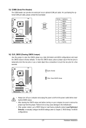
date information and BIOS configurations) and reset the CMOS values to clear the CMOS values (e.g. Failure to do so may cause damage to the motherboard. • After system restart, go to BIOS Setup to load factory defaults (select Load Optimized Defaults) or manually configure the BIOS settings (refer to touch ...
date information and BIOS configurations) and reset the CMOS values to clear the CMOS values (e.g. Failure to do so may cause damage to the motherboard. • After system restart, go to BIOS Setup to load factory defaults (select Load Optimized Defaults) or manually configure the BIOS settings (refer to touch ...


