Manual
Page 4
Table of Contents Box Contents ...6 OptionalItems ...6 GA-G31MX-S2 Motherboard Layout 7 Block Diagram ...8 Chapter 1 Hardware Installation 9 1-1 Installation Precautions 9 1-2 Product Specifications 10 1-3 Installing the CPU and CPU Cooler 13 1-3-1 Installing the CPU 13 1-3-2 Installing the CPU Cooler 15 1-4 Installing the Memory 16 1-4-1 Dual Channel Memory Configuration 16 1-4-2 Installing a Memory 17 1-5 Installing an Expansion Card 18 1-6 Back Panel Connectors 19...
Table of Contents Box Contents ...6 OptionalItems ...6 GA-G31MX-S2 Motherboard Layout 7 Block Diagram ...8 Chapter 1 Hardware Installation 9 1-1 Installation Precautions 9 1-2 Product Specifications 10 1-3 Installing the CPU and CPU Cooler 13 1-3-1 Installing the CPU 13 1-3-2 Installing the CPU Cooler 15 1-4 Installing the Memory 16 1-4-1 Dual Channel Memory Configuration 16 1-4-2 Installing a Memory 17 1-5 Installing an Expansion Card 18 1-6 Back Panel Connectors 19...
Manual
Page 6
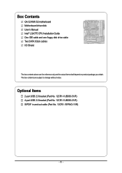
The box contents are for reference only and the actual items shall depend on product package you obtain. Box Contents GA-G31MX-S2 motherboard Motherboard driver disk User's Manual Intel® LGA775 CPU Installation Guide One IDE cable and one floppy disk drive cable Two SATA 3Gb/s cables I/O Shield The box contents above are subject to change without notice. Optional Items 2-port USB 2.0 bracket (Part No. 12CR1-1UB030-51/R) 4-port USB 2.0 bracket (Part No. 12CR1-1UB030-21/R) S/PDIF in and out cable (Part No. 12CR1-1SPINO-11/R) - 6 -
The box contents are for reference only and the actual items shall depend on product package you obtain. Box Contents GA-G31MX-S2 motherboard Motherboard driver disk User's Manual Intel® LGA775 CPU Installation Guide One IDE cable and one floppy disk drive cable Two SATA 3Gb/s cables I/O Shield The box contents above are subject to change without notice. Optional Items 2-port USB 2.0 bracket (Part No. 12CR1-1UB030-51/R) 4-port USB 2.0 bracket (Part No. 12CR1-1UB030-21/R) S/PDIF in and out cable (Part No. 12CR1-1SPINO-11/R) - 6 -
Manual
Page 8
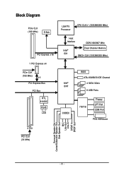
Block Diagram PCIe CLK (100 MHz) D-Sub PCI Express x16 1 PCI Express x4 PCIe CLK (100 MHz) x4 PCI Express Bus PCI Bus RTL 8110SC RJ45 LAN LGA775 Processor CPU CLK+/- (333/266/200 MHz) Host Interface DDR2 800/667 MHz Intel® G31 Dual Channel Memory GMCH CLK (333/266/200 MHz) Intel® ICH7 CODEC BIOS ATA-100/66/33 IDE Channel 4 SATA 3Gb/s 8 USB Ports IT8718 Floppy LPT Port COM Port PS/2 KB/Mouse 2 PCI PCI CLK (33 MHz) Surround Speaker Out Center/Subwoofer Speaker Out Side Speaker Out MIC Line-Out Line-In SPDIF In SPDIF Out - 8 -
Block Diagram PCIe CLK (100 MHz) D-Sub PCI Express x16 1 PCI Express x4 PCIe CLK (100 MHz) x4 PCI Express Bus PCI Bus RTL 8110SC RJ45 LAN LGA775 Processor CPU CLK+/- (333/266/200 MHz) Host Interface DDR2 800/667 MHz Intel® G31 Dual Channel Memory GMCH CLK (333/266/200 MHz) Intel® ICH7 CODEC BIOS ATA-100/66/33 IDE Channel 4 SATA 3Gb/s 8 USB Ports IT8718 Floppy LPT Port COM Port PS/2 KB/Mouse 2 PCI PCI CLK (33 MHz) Surround Speaker Out Center/Subwoofer Speaker Out Side Speaker Out MIC Line-Out Line-In SPDIF In SPDIF Out - 8 -
Manual
Page 9
..., make sure the power supply has been turned off. • Before turning on the computer power during the installation process can become damaged as a motherboard, CPU or memory.
..., make sure the power supply has been turned off. • Before turning on the computer power during the installation process can become damaged as a motherboard, CPU or memory.
Manual
Page 10
...; Pentium® 4 processor/ Intel® Celeron® processor in the LGA 775 package (Go to GIGABYTE's website for the latest CPU support list.) Š Support for Intel® Hyper-Threading Technology Š L2 cache varies with CPU Š 1333/1066/800 MHz FSB Š North Bridge: Intel® G31 Express Chipset Š South... Š Integrated in the South Bridge Š Up to 8 USB 2.0/1.1 ports (4 on the back panel, 4 via the USB brackets connected to the internal USB headers) GA-G31MX-S2 Motherboard - 10 -
...; Pentium® 4 processor/ Intel® Celeron® processor in the LGA 775 package (Go to GIGABYTE's website for the latest CPU support list.) Š Support for Intel® Hyper-Threading Technology Š L2 cache varies with CPU Š 1333/1066/800 MHz FSB Š North Bridge: Intel® G31 Express Chipset Š South... Š Integrated in the South Bridge Š Up to 8 USB 2.0/1.1 ports (4 on the back panel, 4 via the USB brackets connected to the internal USB headers) GA-G31MX-S2 Motherboard - 10 -
Manual
Page 11
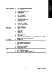
...138; 1 x 4-pin ATX 12V power connector Š 1 x floppy disk drive connector Š 1 x IDE connector Š 4 x SATA 3Gb/s connectors Š 1 x CPU fan header Š 1 x system fan header Š 1 x front panel header Š 1 x front panel audio header Š 1 x CD In connector Š 1 x... Š iTE IT8718 chip Hardware Monitor Š System voltage detection Š CPU/System temperature detection Š CPU/System fan speed detection Š CPU overheating warning Š CPU/System fan fail warning Š CPU fan speed control BIOS Š 1 x 4 Mbit flash Š Use ...
...138; 1 x 4-pin ATX 12V power connector Š 1 x floppy disk drive connector Š 1 x IDE connector Š 4 x SATA 3Gb/s connectors Š 1 x CPU fan header Š 1 x system fan header Š 1 x front panel header Š 1 x front panel audio header Š 1 x CD In connector Š 1 x... Š iTE IT8718 chip Hardware Monitor Š System voltage detection Š CPU/System temperature detection Š CPU/System fan speed detection Š CPU overheating warning Š CPU/System fan fail warning Š CPU fan speed control BIOS Š 1 x 4 Mbit flash Š Use ...

Manual
Page 13
... the power cord from the power outlet before you begin to install the CPU: • Make sure that the motherboard supports the CPU. (Go to GIGABYTE's website for the latest CPU support list.) • Always turn on the computer if the CPU cooler is optimized for HT Technology • A BIOS that supports HT Technology and...
... the power cord from the power outlet before you begin to install the CPU: • Make sure that the motherboard supports the CPU. (Go to GIGABYTE's website for the latest CPU support list.) • Always turn on the computer if the CPU cooler is optimized for HT Technology • A BIOS that supports HT Technology and...

Manual
Page 14
... outlet to prevent damage to correctly install the CPU into the motherboard CPU socket. Step 4: Hold the CPU with the socket alignment keys) and gently insert the CPU into its locked position. CPU Socket Lever Step 1: Completely raise the CPU socket lever. Step 3: Lift the metal load...with the pin one corner of the CPU socket (or you may align the CPU notches with your thumb and index fingers. Step 5: Once the CPU is properly inserted, replace the load plate and push the CPU socket lever back into position. English B. GA-G31MX-S2 Motherboard - 14 - Step 2: Remove ...
... outlet to prevent damage to correctly install the CPU into the motherboard CPU socket. Step 4: Hold the CPU with the socket alignment keys) and gently insert the CPU into its locked position. CPU Socket Lever Step 1: Completely raise the CPU socket lever. Step 3: Lift the metal load...with the pin one corner of the CPU socket (or you may align the CPU notches with your thumb and index fingers. Step 5: Once the CPU is properly inserted, replace the load plate and push the CPU socket lever back into position. English B. GA-G31MX-S2 Motherboard - 14 - Step 2: Remove ...

Manual
Page 15
... the push pin is inserted as the example cooler.) Step 1: Apply an even and thin layer of thermal grease on the surface of the CPU cooler to the CPU fan header (CPU_FAN) on the motherboard. Direction of the Arrow Sign on the Male Push Pin Male Push Pin The Top of Female... direction of the arrow sign on the male push pin. (Turning the push pin along the direction of the motherboard. Inadequately removing the CPU cooler may adhere to the CPU. Step 4: You should hear a "click" when pushing down on the push pins diagonally. Step 6: Finally, attach the power connector of the installed...
... the push pin is inserted as the example cooler.) Step 1: Apply an even and thin layer of thermal grease on the surface of the CPU cooler to the CPU fan header (CPU_FAN) on the motherboard. Direction of the Arrow Sign on the Male Push Pin Male Push Pin The Top of Female... direction of the arrow sign on the male push pin. (Turning the push pin along the direction of the motherboard. Inadequately removing the CPU cooler may adhere to the CPU. Step 4: You should hear a "click" when pushing down on the push pins diagonally. Step 6: Finally, attach the power connector of the installed...
Manual
Page 22
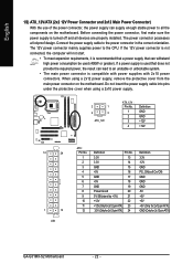
... 3.3V -12V GND PS_ON(soft On/Off) GND GND GND -5V +5V +5V +5V (Only for 2x12-pin ATX) GND (Only for 2x12-pin ATX) GA-G31MX-S2 Motherboard - 22 - The 12V power connector mainly supplies power to the power connector in the correct orientation. If a power supply is used that does not... power connector, first make sure the power supply is turned off and all the components on the motherboard. Connect the power supply cable to the CPU.
... 3.3V -12V GND PS_ON(soft On/Off) GND GND GND -5V +5V +5V +5V (Only for 2x12-pin ATX) GND (Only for 2x12-pin ATX) GA-G31MX-S2 Motherboard - 22 - The 12V power connector mainly supplies power to the power connector in the correct orientation. If a power supply is used that does not... power connector, first make sure the power supply is turned off and all the components on the motherboard. Connect the power supply cable to the CPU.
Manual
Page 23
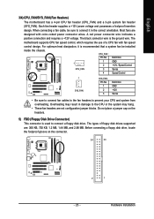
.... Overheating may result in the correct orientation. Hardware Installation CPU_FAN : Pin No. For optimum heat dissipation, it in damage to prevent your CPU and system from overheating. Do not place a jumper cap on the connector. 34 33 2 1 - 23 - Most fans are not ... and requires a +12V voltage. The black connector wire is the ground wire. English 3/4) CPU_FAN/SYS_FAN (Fan Headers) The motherboard has a 4-pin CPU fan header (CPU_FAN) and a 3-pin system fan header (SYS_FAN). When connecting a fan cable, be installed inside the chassis. Each fan header supplies...
.... Overheating may result in the correct orientation. Hardware Installation CPU_FAN : Pin No. For optimum heat dissipation, it in damage to prevent your CPU and system from overheating. Do not place a jumper cap on the connector. 34 33 2 1 - 23 - Most fans are not ... and requires a +12V voltage. The black connector wire is the ground wire. English 3/4) CPU_FAN/SYS_FAN (Fan Headers) The motherboard has a 4-pin CPU fan header (CPU_FAN) and a 3-pin system fan header (SYS_FAN). When connecting a fan cable, be installed inside the chassis. Each fan header supplies...
Manual
Page 34
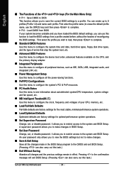
... this menu to configure the system's PCI & PnP resources. „ PC Health Status Use this menu to see information about autodetected system/CPU temperature, system voltage and fan speed, etc. „ MB Intelligent Tweaker(M.I.T.) Use this task.) „ Exit Without Saving Abandon all the...allows you to restrict access to the system and BIOS Setup. First enter the profile name (to erase the default profile name, use this task.) GA-G31MX-S2 Motherboard - 34 - A supervisor password allows you to a profile. English „ The Functions of the and keys (For the Main Menu Only)...
... this menu to configure the system's PCI & PnP resources. „ PC Health Status Use this menu to see information about autodetected system/CPU temperature, system voltage and fan speed, etc. „ MB Intelligent Tweaker(M.I.T.) Use this task.) „ Exit Without Saving Abandon all the...allows you to restrict access to the system and BIOS Setup. First enter the profile name (to erase the default profile name, use this task.) GA-G31MX-S2 Motherboard - 34 - A supervisor password allows you to a profile. English „ The Functions of the and keys (For the Main Menu Only)...

Manual
Page 37
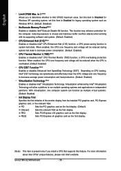
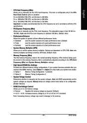
...booting the system and for operating systems that support multi-processors mode. (Default: Enabled) (Note) This item is installed. (Default: Disabled) CPU Hyper-Threading (Note) Enables or disables Intel® Hyper-Threading Technology. Use the up or down arrow key to select a hard drive, ... the hard drive and to exit this menu when finished. to 3 (Note) No-Execute Memory Protect (Note) CPU Enhanced Halt (C1E) (Note) CPU Thermal Monitor 2(TM2) (Note) CPU EIST Function (Note) Virtualization Technology (Note) Init Display First Onboard VGA On-Chip Frame Buffer Size [Press Enter]...
...booting the system and for operating systems that support multi-processors mode. (Default: Enabled) (Note) This item is installed. (Default: Disabled) CPU Hyper-Threading (Note) Enables or disables Intel® Hyper-Threading Technology. Use the up or down arrow key to select a hard drive, ... the hard drive and to exit this menu when finished. to 3 (Note) No-Execute Memory Protect (Note) CPU Enhanced Halt (C1E) (Note) CPU Thermal Monitor 2(TM2) (Note) CPU EIST Function (Note) Virtualization Technology (Note) Init Display First Onboard VGA On-Chip Frame Buffer Size [Press Enter]...
Manual
Page 38
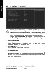
... attacks when working with its supporting software and system. (Default: Enabled) CPU Enhanced Halt (C1E) (Note) Enables or disables Intel® CPU Enhanced Halt (C1E) function, a CPU power-saving function in independent partitions. PEG Sets PCI Express x16 graphics card... Technology (Note) Enables or disables Intel® Virtualization Technology. GA-G31MX-S2 Motherboard - 38 - PEG2 Sets PCI Express x4 graphics card as the first display. (Note) This item is overheated. (Default: Enabled) CPU EIST Function (Note) Enables or disables Enhanced Intel SpeedStep Technology...
... attacks when working with its supporting software and system. (Default: Enabled) CPU Enhanced Halt (C1E) (Note) Enables or disables Intel® CPU Enhanced Halt (C1E) function, a CPU power-saving function in independent partitions. PEG Sets PCI Express x16 graphics card... Technology (Note) Enables or disables Intel® Virtualization Technology. GA-G31MX-S2 Motherboard - 38 - PEG2 Sets PCI Express x4 graphics card as the first display. (Note) This item is overheated. (Default: Enabled) CPU EIST Function (Note) Enables or disables Enhanced Intel SpeedStep Technology...
Manual
Page 46
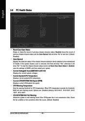
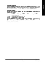
... fan is removed, this occurs. (Default: Disabled) GA-G31MX-S2 Motherboard - 46 - CPU Warning Temperature Sets the warning threshold for CPU temperature. Enabled clears the record of previous chassis intrusion status and the Case Opened field will show "No". Current System/CPU Temperature Displays current system/CPU temperature. When CPU temperature exceeds the threshold, BIOS will show "No...
... fan is removed, this occurs. (Default: Disabled) GA-G31MX-S2 Motherboard - 46 - CPU Warning Temperature Sets the warning threshold for CPU temperature. Enabled clears the record of previous chassis intrusion status and the Case Opened field will show "No". Current System/CPU Temperature Displays current system/CPU temperature. When CPU temperature exceeds the threshold, BIOS will show "No...
Manual
Page 47
... is not designed following Intel PWM fan specifications, selecting PWM mode may not effectively reduce the fan speed. - 47 - PWM Sets PWM mode for a 3-pin CPU fan. Note: The Voltage mode can adjust the fan speed with EasyTune based on system requirements. You can be set to Enabled. If disabled...
... is not designed following Intel PWM fan specifications, selecting PWM mode may not effectively reduce the fan speed. - 47 - PWM Sets PWM mode for a 3-pin CPU fan. Note: The Voltage mode can adjust the fan speed with EasyTune based on system requirements. You can be set to Enabled. If disabled...
Manual
Page 48
...is present only if a CPU with unlocked clock ratio is recommended that supports this feature. If this occurs, clear the CMOS values and reset the board to default values.) • When the System Voltage Optimized item blinks in red, it is installed. GA-G31MX-S2 Motherboard - 48 - mode... based on system configurations. CPU Clock Ratio (Note) Allows you set the R.G.B. Enabled will allow for advanced users only and we recommend you install...
...is present only if a CPU with unlocked clock ratio is recommended that supports this feature. If this occurs, clear the CMOS values and reset the board to default values.) • When the System Voltage Optimized item blinks in red, it is installed. GA-G31MX-S2 Motherboard - 48 - mode... based on system configurations. CPU Clock Ratio (Note) Allows you set the R.G.B. Enabled will allow for advanced users only and we recommend you install...
Manual
Page 49
... you overclock the DDR2 memory, select Option 1 or Option 2 to manually set the CPU host frequency. Note: Increasing memory voltage may result in accordance with the CPU specifications. For a 1333 MHz FSB CPU, set this item to manually set the system voltages. High Speed DRAM DLL Settings Provides...as required. (Default) +0.1V ~ +0.4V Increases memory voltage by 0.1V to 0.4V at its good performance level. For an 800 MHz FSB CPU, set this item to 266 MHz. PCI Express Frequency (Mhz) Allows you to set the system memory multiplier. Extreme Lets the system operate at ...
... you overclock the DDR2 memory, select Option 1 or Option 2 to manually set the CPU host frequency. Note: Increasing memory voltage may result in accordance with the CPU specifications. For a 1333 MHz FSB CPU, set this item to manually set the system voltages. High Speed DRAM DLL Settings Provides...as required. (Default) +0.1V ~ +0.4V Increases memory voltage by 0.1V to 0.4V at its good performance level. For an 800 MHz FSB CPU, set this item to 266 MHz. PCI Express Frequency (Mhz) Allows you to set the system memory multiplier. Extreme Lets the system operate at ...
Manual
Page 50
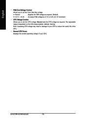
...voltage as required. The adjustable range is dependent on the CPU being installed. (Default: Normal) Note: Increasing CPU voltage may result in damage to your CPU or reduce the useful life of your CPU. Normal sets the CPU voltage as required. (Default) Increases FSB voltage by 0....1V to 0.3V at 0.1V increment. Normal CPU Vcore Displays the normal operating voltage of the CPU. CPU Voltage Control Allows you to set the CPU voltage. GA-G31MX-S2...
...voltage as required. The adjustable range is dependent on the CPU being installed. (Default: Normal) Note: Increasing CPU voltage may result in damage to your CPU or reduce the useful life of your CPU. Normal sets the CPU voltage as required. (Default) Increases FSB voltage by 0....1V to 0.3V at 0.1V increment. Normal CPU Vcore Displays the normal operating voltage of the CPU. CPU Voltage Control Allows you to set the CPU voltage. GA-G31MX-S2...
Manual
Page 69
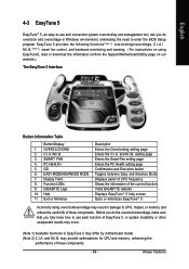
...page Confirmation and Execution button Toggles between Easy and Advance Mode Displays panel of CPU frequency Shows the information of the current function Visits GIGABYTE website Displays EasyTuneTM 5 help screen Quits or minimizes EasyTuneTM 5 Incorrectly doing overclock.../overvoltage may result in damage to CPU, chipset, or memory and reduce the useful life of these components. - 69 - EasyTune 5 provides the following ...
...page Confirmation and Execution button Toggles between Easy and Advance Mode Displays panel of CPU frequency Shows the information of the current function Visits GIGABYTE website Displays EasyTuneTM 5 help screen Quits or minimizes EasyTuneTM 5 Incorrectly doing overclock.../overvoltage may result in damage to CPU, chipset, or memory and reduce the useful life of these components. - 69 - EasyTune 5 provides the following ...


