Manual
Page 1
GA-EX58-UD3R LGA1366 socket motherboard for Intel® Core™ i7 processor family User's Manual Rev. 1701 12ME-EX58UD3R-1701R
GA-EX58-UD3R LGA1366 socket motherboard for Intel® Core™ i7 processor family User's Manual Rev. 1701 12ME-EX58UD3R-1701R
Manual
Page 2
Motherboard GA-EX58-UD3R May 8, 2009 Motherboard GA-EX58-UD3R May 8, 2009
Motherboard GA-EX58-UD3R May 8, 2009 Motherboard GA-EX58-UD3R May 8, 2009
Manual
Page 3
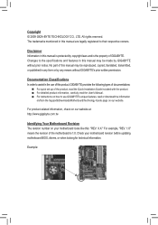
..., copied, translated, transmitted, or published in the use GIGABYTE's unique features, read or download the information on/from the Support&Downloads\Motherboard\Technology Guide page on your motherboard revision before updating motherboard BIOS, drivers, or when looking for technical information. No... or by any means without prior notice. For product-related information, check on our website at: http://www.gigabyte.com.tw Identifying Your Motherboard Revision The revision number on our website. Disclaimer Information in this : "REV: X.X." Documentation Classifications In order ...
..., copied, translated, transmitted, or published in the use GIGABYTE's unique features, read or download the information on/from the Support&Downloads\Motherboard\Technology Guide page on your motherboard revision before updating motherboard BIOS, drivers, or when looking for technical information. No... or by any means without prior notice. For product-related information, check on our website at: http://www.gigabyte.com.tw Identifying Your Motherboard Revision The revision number on our website. Disclaimer Information in this : "REV: X.X." Documentation Classifications In order ...
Manual
Page 4
Table of Contents Box Contents...6 Optional Items...6 GA-EX58-UD3R Motherboard Layout 7 Block Diagram...8 Chapter 1 Hardware Installation 9 1-1 Installation Precautions 9 1-2 Product Specifications 10 1-3 Installing the CPU and CPU Cooler 13 1-3-1 Installing the CPU 13 1-3-2 Installing the CPU ...
Table of Contents Box Contents...6 Optional Items...6 GA-EX58-UD3R Motherboard Layout 7 Block Diagram...8 Chapter 1 Hardware Installation 9 1-1 Installation Precautions 9 1-2 Product Specifications 10 1-3 Installing the CPU and CPU Cooler 13 1-3-1 Installing the CPU 13 1-3-2 Installing the CPU ...
Manual
Page 6
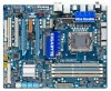
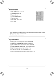
Box Contents GA-EX58-UD3R motherboard Motherboard driver disk User's Manual Quick Installation Guide One IDE cable Four SATA 3Gb/s cables I/O Shield • The box contents above are subject to change without notice. • The motherboard image is for reference only and the actual items shall depend on the product package you obtain. Optional Items Floppy disk...
Box Contents GA-EX58-UD3R motherboard Motherboard driver disk User's Manual Quick Installation Guide One IDE cable Four SATA 3Gb/s cables I/O Shield • The box contents above are subject to change without notice. • The motherboard image is for reference only and the actual items shall depend on the product package you obtain. Optional Items Floppy disk...
Manual
Page 7
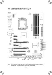
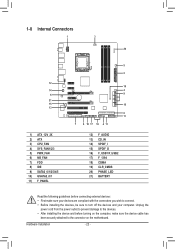
..., use other expansion slots. - 7 - GA-EX58-UD3R Motherboard Layout KB_MS R_SPDIF ATX_12V_2X USB_1394_1 USB_1394_2 R_USB USB_LAN LGA1366 CPU_FAN PHASE LED PWR_FAN GA-EX58-UD3R AUDIO F_AUDIO PCIEX1_1 (Note) RTL8111C PCIEX1_2 Intel® X58 SPDIF_I NB_FAN CODEC PCIEX4_1 BATTERY PCIEX16_1 IT8720 CD_IN SPDIF_O PCI1 PCI2 PCIEX16_2 TSB43AB23 DDR3_1 DDR3_3 DDR3_2 DDR3_4 Intel® ICH10R GIGABYTE SATA2 CLR_CMOS ATX SYS_FAN1...
..., use other expansion slots. - 7 - GA-EX58-UD3R Motherboard Layout KB_MS R_SPDIF ATX_12V_2X USB_1394_1 USB_1394_2 R_USB USB_LAN LGA1366 CPU_FAN PHASE LED PWR_FAN GA-EX58-UD3R AUDIO F_AUDIO PCIEX1_1 (Note) RTL8111C PCIEX1_2 Intel® X58 SPDIF_I NB_FAN CODEC PCIEX4_1 BATTERY PCIEX16_1 IT8720 CD_IN SPDIF_O PCI1 PCI2 PCIEX16_2 TSB43AB23 DDR3_1 DDR3_3 DDR3_2 DDR3_4 Intel® ICH10R GIGABYTE SATA2 CLR_CMOS ATX SYS_FAN1...
Manual
Page 9
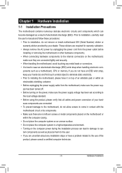
... the product, please verify that all cables and power connectors of your hardware components are connected. • To prevent damage to the motherboard, do not allow screws to come in a high-temperature environment. • Turning on the power, make sure they are uncertain about...an electrostatic discharge (ESD) wrist strap when handling electronic com- If you are connected tightly and securely. • When handling the motherboard, avoid touching any installation steps or have an ESD wrist strap, keep your dealer. Hardware Installation Prior to installation, carefully read the...
... the product, please verify that all cables and power connectors of your hardware components are connected. • To prevent damage to the motherboard, do not allow screws to come in a high-temperature environment. • Turning on the power, make sure they are uncertain about...an electrostatic discharge (ESD) wrist strap when handling electronic com- If you are connected tightly and securely. • When handling the motherboard, avoid touching any installation steps or have an ESD wrist strap, keep your dealer. Hardware Installation Prior to installation, carefully read the...
Manual
Page 12
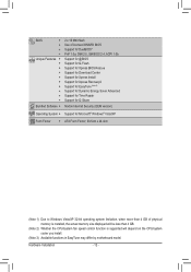
... CPU/system fan speed control function is supported will depend on the CPU/system cooler you install. (Note 3) Available functions in EasyTune may differ by motherboard model.
... CPU/system fan speed control function is supported will depend on the CPU/system cooler you install. (Note 3) Available functions in EasyTune may differ by motherboard model.

Manual
Page 13
... A. It is not installed, otherwise overheating and dam- Locate the alignment keys on the motherboard CPU socket and the notches on the computer if the CPU cooler is not recommended that the motherboard supports the CPU. (Go to GIGABYTE's website for the peripherals. Hardware Installation The CPU cannot be inserted if oriented incorrectly...
... A. It is not installed, otherwise overheating and dam- Locate the alignment keys on the motherboard CPU socket and the notches on the computer if the CPU cooler is not recommended that the motherboard supports the CPU. (Go to GIGABYTE's website for the peripherals. Hardware Installation The CPU cannot be inserted if oriented incorrectly...
Manual
Page 14
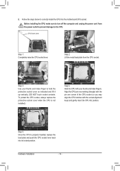
... socket lever. Step 5: Once the CPU is not installed.) Step 4: Hold the CPU with the socket alignment keys) and gently insert the CPU into the motherboard CPU socket. Before installing the CPU, make sure to correctly install the CPU into position. Hardware Installation - 14 -
... socket lever. Step 5: Once the CPU is not installed.) Step 4: Hold the CPU with the socket alignment keys) and gently insert the CPU into the motherboard CPU socket. Before installing the CPU, make sure to correctly install the CPU into position. Hardware Installation - 14 -

Manual
Page 15
... for instructions on installing the cooler.) Step 5: After the installation, check the back of the CPU cooler to the CPU fan header (CPU_FAN) on the motherboard. If the push pin is inserted as the example cooler.) Step 1: Apply an even and thin layer of thermal grease on the surface of arrow... and CPU may damage the CPU. - 15 - Inadequately removing the CPU cooler may adhere to the CPU. Step 6: Finally, attach the power connector of the motherboard. Direction of the Arrow Sign on the Male Push Pin Male Push Pin The Top of Female Push Pin Female Push Pin Step 2: Before installing...
... for instructions on installing the cooler.) Step 5: After the installation, check the back of the CPU cooler to the CPU fan header (CPU_FAN) on the motherboard. If the push pin is inserted as the example cooler.) Step 1: Apply an even and thin layer of thermal grease on the surface of arrow... and CPU may damage the CPU. - 15 - Inadequately removing the CPU cooler may adhere to the CPU. Step 6: Finally, attach the power connector of the motherboard. Direction of the Arrow Sign on the Male Push Pin Male Push Pin The Top of Female Push Pin Female Push Pin Step 2: Before installing...
Manual
Page 16
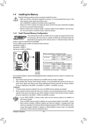
...or 3 Channel memory mode may double or triple the original memory bandwidth. Hardware Installation - 16 - After the memory is recommended that the motherboard supports the memory. When enabling 3 Channel mode with three memory modules, be sure to install them in Flex Memory Mode will automatically detect the...memory in Dual or 3 Channel mode. When enabling Dual Channel mode with two memory modules, be sure to be used . (Go to GIGABYTE's website for the latest memory support list.) • Always turn off the computer and unplug the power cord from the power outlet before ...
...or 3 Channel memory mode may double or triple the original memory bandwidth. Hardware Installation - 16 - After the memory is recommended that the motherboard supports the memory. When enabling 3 Channel mode with three memory modules, be sure to install them in Flex Memory Mode will automatically detect the...memory in Dual or 3 Channel mode. When enabling Dual Channel mode with two memory modules, be sure to be used . (Go to GIGABYTE's website for the latest memory support list.) • Always turn off the computer and unplug the power cord from the power outlet before ...
Manual
Page 17
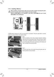
... and unplug the power cord from the power outlet to prevent damage to install DDR3 DIMMs on the socket. Place the memory module on this motherboard. Follow the steps below to correctly install your fingers on the top edge of the memory module. DDR3 and DDR2 DIMMs are not compatible to...
... and unplug the power cord from the power outlet to prevent damage to install DDR3 DIMMs on the socket. Place the memory module on this motherboard. Follow the steps below to correctly install your fingers on the top edge of the memory module. DDR3 and DDR2 DIMMs are not compatible to...
Manual
Page 18
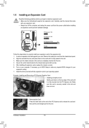
Turn on the top edge of the PCI Express slot to install an expansion card: • Make sure the motherboard supports the expansion card. If necessary, go to BIOS Setup to correctly install your expansion card in the slot and does not rock. • Removing ...
Turn on the top edge of the PCI Express slot to install an expansion card: • Make sure the motherboard supports the expansion card. If necessary, go to BIOS Setup to correctly install your expansion card in the slot and does not rock. • Removing ...
Manual
Page 19
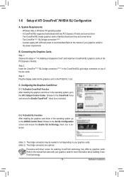
A CrossFireX/SLI-supported motherboard with your graphics cards for more information about enabling CrossFireX technology. - 19 - Two CrossFire (Note 1)/SLI bridge connectors (Note 2) - A power supply with sufficient power is ...
A CrossFireX/SLI-supported motherboard with your graphics cards for more information about enabling CrossFireX technology. - 19 - Two CrossFire (Note 1)/SLI bridge connectors (Note 2) - A power supply with sufficient power is ...
Manual
Page 20
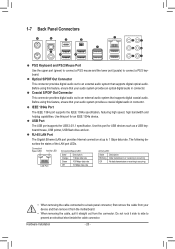
... from the connector. Before using this port for an IEEE 1394a device. Use this feature, ensure that your device and then remove it from the motherboard. • When removing the cable, pull it side to side to an external audio system that your audio system provides a coaxial digital audio in connector...
... from the connector. Before using this port for an IEEE 1394a device. Use this feature, ensure that your device and then remove it from the motherboard. • When removing the cable, pull it side to side to an external audio system that your audio system provides a coaxial digital audio in connector...
Manual
Page 22
... devices and your devices are compliant with the connectors you wish to connect. • Before installing the devices, be sure to the connector on the motherboard.
... devices and your devices are compliant with the connectors you wish to connect. • Before installing the devices, be sure to the connector on the motherboard.

Manual
Page 23
If a power supply is turned off and all the components on the motherboard. Definition 1 GND (Only for 2x4-pin 12V) 2 GND (Only for 2x4-pin 12V) 5 1 ATX_12V_2X 3 GND 4 GND 5 +12V (Only for 2x4-pin 12V) 6 +12V (Only for ... a power supply providing a 2x4 12V and a 2x12 power connector, remove the protective covers from the 12V power connector and the main power connector on the motherboard. Connect the power supply cable to the CPU. The 12V power connector mainly supplies power to the power connector in the correct orientation. Hardware Installation...
If a power supply is turned off and all the components on the motherboard. Definition 1 GND (Only for 2x4-pin 12V) 2 GND (Only for 2x4-pin 12V) 5 1 ATX_12V_2X 3 GND 4 GND 5 +12V (Only for 2x4-pin 12V) 6 +12V (Only for ... a power supply providing a 2x4 12V and a 2x12 power connector, remove the protective covers from the 12V power connector and the main power connector on the motherboard. Connect the power supply cable to the CPU. The 12V power connector mainly supplies power to the power connector in the correct orientation. Hardware Installation...
Manual
Page 24
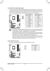
... When connecting a fan cable, be installed inside the chassis. A red power connector wire indicates a positive connection and requires a +12V voltage. The motherboard supports CPU fan speed con- Pin No. Definition 1 1 GND 2 +12V / Speed Control CPU_FAN 3 Sense 4 Speed Control 1 SYS_FAN2 SYS_FAN2: ...Bridge fan cable to prevent your CPU, North Bridge and system from overheating. 3/4/5) CPU_FAN/SYS_FAN1/SYS_FAN2/SYS_FAN3/PWR_FAN (Fan Headers) The motherboard has a 4-pin CPU fan header (CPU_FAN), a 4-pin (SYS_FAN2) and two 3-pin (SYS_ FAN1/SYS_FAN3) system fan headers...
... When connecting a fan cable, be installed inside the chassis. A red power connector wire indicates a positive connection and requires a +12V voltage. The motherboard supports CPU fan speed con- Pin No. Definition 1 1 GND 2 +12V / Speed Control CPU_FAN 3 Sense 4 Speed Control 1 SYS_FAN2 SYS_FAN2: ...Bridge fan cable to prevent your CPU, North Bridge and system from overheating. 3/4/5) CPU_FAN/SYS_FAN1/SYS_FAN2/SYS_FAN3/PWR_FAN (Fan Headers) The motherboard has a 4-pin CPU fan header (CPU_FAN), a 4-pin (SYS_FAN2) and two 3-pin (SYS_ FAN1/SYS_FAN3) system fan headers...
Manual
Page 28
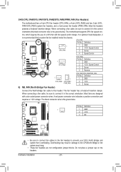
Incorrect connection between the module connector and the motherboard header will be present on both of a single plug. For HD Front Panel Audio: Pin No. Definition For AC'97 Front Panel Audio: Pin No. ... audio connections simultaneously. If your chassis provides an AC'97 front panel audio module, refer to this header. Make sure the wire assignments of the motherboard header. If you want to mute the back panel audio (only supported when using an HD front panel audio module), refer to Chapter 5, "Configuring 2/4/5.1/7.1-Channel...
Incorrect connection between the module connector and the motherboard header will be present on both of a single plug. For HD Front Panel Audio: Pin No. Definition For AC'97 Front Panel Audio: Pin No. ... audio connections simultaneously. If your chassis provides an AC'97 front panel audio module, refer to this header. Make sure the wire assignments of the motherboard header. If you want to mute the back panel audio (only supported when using an HD front panel audio module), refer to Chapter 5, "Configuring 2/4/5.1/7.1-Channel...


