Manual
Page 3
... manual may be made by GIGABYTE without GIGABYTE's prior written permission. For example, "REV: 1.0" means the revision of the product, read the Quick Installation Guide included with the product. For detailed product information, carefully read or download the information on/from the Support&Downloads\Motherboard\Technology Guide page on your motherboard revision before updating motherboard BIOS, drivers, or when looking for technical information. Copyright © 2009 GIGA...
... manual may be made by GIGABYTE without GIGABYTE's prior written permission. For example, "REV: 1.0" means the revision of the product, read the Quick Installation Guide included with the product. For detailed product information, carefully read or download the information on/from the Support&Downloads\Motherboard\Technology Guide page on your motherboard revision before updating motherboard BIOS, drivers, or when looking for technical information. Copyright © 2009 GIGA...
Manual
Page 4
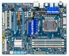
......6 GA-EX58-UD3R Motherboard Layout 7 Block Diagram...8 Chapter 1 Hardware Installation 9 1-1 Installation Precautions 9 1-2 Product Specifications 10 1-3 Installing the CPU and CPU Cooler 13 1-3-1 Installing the CPU 13 1-3-2 Installing the CPU Cooler 15 1-4 Installing the Memory 16 1-4-1 Dual/3 Channel Memory Configuration 16 1-4-2 Installing a Memory 17 1-5 Installing an Expansion Card 18 1-6 Setup of ATI CrossFireX™/NVIDIA SLI Configuration 19 1-7 Back Panel Connectors 20 1-8 Internal Connectors 22 Chapter 2 BIOS Setup 33 2-1 Startup Screen 34 2-2 The Main Menu 35...
......6 GA-EX58-UD3R Motherboard Layout 7 Block Diagram...8 Chapter 1 Hardware Installation 9 1-1 Installation Precautions 9 1-2 Product Specifications 10 1-3 Installing the CPU and CPU Cooler 13 1-3-1 Installing the CPU 13 1-3-2 Installing the CPU Cooler 15 1-4 Installing the Memory 16 1-4-1 Dual/3 Channel Memory Configuration 16 1-4-2 Installing a Memory 17 1-5 Installing an Expansion Card 18 1-6 Setup of ATI CrossFireX™/NVIDIA SLI Configuration 19 1-7 Back Panel Connectors 20 1-8 Internal Connectors 22 Chapter 2 BIOS Setup 33 2-1 Startup Screen 34 2-2 The Main Menu 35...
Manual
Page 10
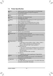
...NVIDIA SLI technology and conform to PCI Express 2.0 standard 1 x PCI Express x4 slot 2 x PCI Express x1 slots 2 x PCI slots Storage Interface South Bridge: - 6 x SATA 3Gb/s connectors (SATA2_0, SATA2_1, SATA2_2, SATA2_3, SATA2_4, SATA2_5) supporting up to 6 SATA 3Gb/s devices - 1-2 Product Specifications CPU Support for an Intel® Core™ i7 series processor in the South Bridge Up to 12 USB 2.0/1.1 ports (8 on the back panel, 1 via the USB brackets connected to the internal USB headers...
...NVIDIA SLI technology and conform to PCI Express 2.0 standard 1 x PCI Express x4 slot 2 x PCI Express x1 slots 2 x PCI slots Storage Interface South Bridge: - 6 x SATA 3Gb/s connectors (SATA2_0, SATA2_1, SATA2_2, SATA2_3, SATA2_4, SATA2_5) supporting up to 6 SATA 3Gb/s devices - 1-2 Product Specifications CPU Support for an Intel® Core™ i7 series processor in the South Bridge Up to 12 USB 2.0/1.1 ports (8 on the back panel, 1 via the USB brackets connected to the internal USB headers...
Manual
Page 16
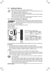
... the motherboard supports the memory. Intel Flex Memory Technology offers greater flexibility to upgrade by allowing different memory sizes to prevent hardware damage. • Memory modules have a foolproof design. DS/SS - - When enabling Dual Channel mode with two memory modules, be sure to install them in the DDR3_1, DDR3_2 and DDR3_4 sockets. • For the DDR3_2/DDR3_3 memory socket, make sure the memory module to be used . Hardware Installation - 16 - A memory module...
... the motherboard supports the memory. Intel Flex Memory Technology offers greater flexibility to upgrade by allowing different memory sizes to prevent hardware damage. • Memory modules have a foolproof design. DS/SS - - When enabling Dual Channel mode with two memory modules, be sure to install them in the DDR3_1, DDR3_2 and DDR3_4 sockets. • For the DDR3_2/DDR3_3 memory socket, make sure the memory module to be used . Hardware Installation - 16 - A memory module...
Manual
Page 18
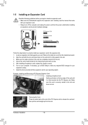
... the power cord from the slot. Locate an expansion slot that came with the expansion card in your expansion card in the expansion slot. 1. Align the card with a screw. 5. Make sure the card is fully inserted into the slot. 4. Hardware Installation - 18 - Carefully read the manual that supports your computer. Remove the metal slot cover from the chassis back panel. 2. If necessary, go to BIOS Setup to the chassis back panel...
... the power cord from the slot. Locate an expansion slot that came with the expansion card in your expansion card in the expansion slot. 1. Align the card with a screw. 5. Make sure the card is fully inserted into the slot. 4. Hardware Installation - 18 - Carefully read the manual that supports your computer. Remove the metal slot cover from the chassis back panel. 2. If necessary, go to BIOS Setup to the chassis back panel...
Manual
Page 19
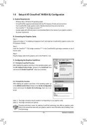
...) B. Configuring the Graphics Card Driver C-1. Browse to the Set SLI Configuration screen and ensure the Enable SLI technology check box is selected. (Note 1) The bridge connectors may differ by graphics cards. Connecting the Graphics Cards Step 1: Observe the steps in the CrossFireX/SLI gold edge connectors on the PCI Express x16 slots. C-2. Refer to the manual of the two cards. Step 3: Plug the display cable into the graphics card on your graphics cards. (Note 2) The bridge connectors are optional. Procedure and driver screen for enabling CrossFireX technology...
...) B. Configuring the Graphics Card Driver C-1. Browse to the Set SLI Configuration screen and ensure the Enable SLI technology check box is selected. (Note 1) The bridge connectors may differ by graphics cards. Connecting the Graphics Cards Step 1: Observe the steps in the CrossFireX/SLI gold edge connectors on the PCI Express x16 slots. C-2. Refer to the manual of the two cards. Step 3: Plug the display cable into the graphics card on your graphics cards. (Note 2) The bridge connectors are optional. Procedure and driver screen for enabling CrossFireX technology...
Manual
Page 24
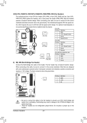
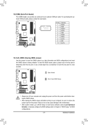
... the use of a CPU fan with color-coded power connector wires. Definition 1 GND 2 +12V / Speed Control 3 Sense 4 Reserve 1 SYS_FAN3 1 SYS_FAN1/ PWR_FAN SYS_FAN1/SYS_FAN3/PWR_FAN: Pin No. Definition 1 1 GND 2 +12V 3 NC • Be sure to connect fan cables to the fan headers to connect it is the ground wire. Most fans are not configuration jumper blocks. Most fan headers possess a foolproof insertion design. When connecting a fan cable, be installed inside the chassis. The motherboard supports CPU fan speed con- Definition 1 1 GND 2 +12V / Speed Control CPU_FAN...
... the use of a CPU fan with color-coded power connector wires. Definition 1 GND 2 +12V / Speed Control 3 Sense 4 Reserve 1 SYS_FAN3 1 SYS_FAN1/ PWR_FAN SYS_FAN1/SYS_FAN3/PWR_FAN: Pin No. Definition 1 1 GND 2 +12V 3 NC • Be sure to connect fan cables to the fan headers to connect it is the ground wire. Most fans are not configuration jumper blocks. Most fan headers possess a foolproof insertion design. When connecting a fan cable, be installed inside the chassis. The motherboard supports CPU fan speed con- Definition 1 1 GND 2 +12V / Speed Control CPU_FAN...
Manual
Page 31
... power cord from the power outlet before clearing the CMOS values. • After clearing the CMOS values and before turning on the two pins to temporarily short the two pins or use a metal object like a screwdriver to Chapter 2, "BIOS Setup," for a few seconds. Failure to do so may cause damage to the motherboard. • After system restart, go to BIOS Setup to load factory defaults (select Load Optimized Defaults) or manually configure the BIOS settings...
... power cord from the power outlet before clearing the CMOS values. • After clearing the CMOS values and before turning on the two pins to temporarily short the two pins or use a metal object like a screwdriver to Chapter 2, "BIOS Setup," for a few seconds. Failure to do so may cause damage to the motherboard. • After system restart, go to BIOS Setup to load factory defaults (select Load Optimized Defaults) or manually configure the BIOS settings...
Manual
Page 34
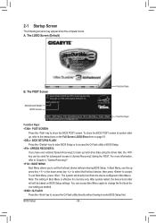
... boots. Motherboard Model BIOS Version EX58-UD3R E3 . . . . : BIOS Setup : XpressRecovery2 : Boot Menu : Qflash 04/13/2009-X58-ICH10-7A89QG0EC-00 Function Keys Function Keys Function Keys: : POST SCREEN Press the key to show the BIOS POST screen at system startup, refer to enter BIOS Setup first. You can be used for one time only. The POST Screen Award Modular BIOS v6.00PG, An Energy Star Ally Copyright (C) 1984-2009, Award Software, Inc. In Boot Menu, use the up hard drive data using the driver disk, the key can access Boot Menu...
... boots. Motherboard Model BIOS Version EX58-UD3R E3 . . . . : BIOS Setup : XpressRecovery2 : Boot Menu : Qflash 04/13/2009-X58-ICH10-7A89QG0EC-00 Function Keys Function Keys Function Keys: : POST SCREEN Press the key to show the BIOS POST screen at system startup, refer to enter BIOS Setup first. You can be used for one time only. The POST Screen Award Modular BIOS v6.00PG, An Energy Star Ally Copyright (C) 1984-2009, Award Software, Inc. In Boot Menu, use the up hard drive data using the driver disk, the key can access Boot Menu...
Manual
Page 36
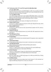
... key) and then press to complete. F12: Load CMOS from BIOS If your CPU, memory, etc. Standard CMOS Features Use this menu to configure the system time and date, hard drive types, floppy disk drive types, and the type of your system becomes unstable and you have loaded the BIOS default settings, you to view the BIOS settings but not to see information about autodetected system/CPU temperature, system voltage and fan speed, etc. Load Fail-Safe Defaults Fail-Safe defaults...
... key) and then press to complete. F12: Load CMOS from BIOS If your CPU, memory, etc. Standard CMOS Features Use this menu to configure the system time and date, hard drive types, floppy disk drive types, and the type of your system becomes unstable and you have loaded the BIOS default settings, you to view the BIOS settings but not to see information about autodetected system/CPU temperature, system voltage and fan speed, etc. Load Fail-Safe Defaults Fail-Safe defaults...
Manual
Page 50
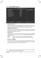
...Device Third Boot Device Password Check HDD S.M.A.R.T. Options are: Floppy, LS120, Hard Disk, CDROM, ZIP, USB-FDD, USB-ZIP, USB-CDROM, USB-HDD, Legacy LAN, Disabled. Capability Enables or disables the S.M.A.R.T. (Self Monitoring and Reporting Technology) capability of your system to report read/write errors of loading the operating system from the available devices. Setup A password is only required for entering the BIOS Setup program. (Default) System A password is required every time the system boots, or only when you install a CPU that supports this item, set...
...Device Third Boot Device Password Check HDD S.M.A.R.T. Options are: Floppy, LS120, Hard Disk, CDROM, ZIP, USB-FDD, USB-ZIP, USB-CDROM, USB-HDD, Legacy LAN, Disabled. Capability Enables or disables the S.M.A.R.T. (Self Monitoring and Reporting Technology) capability of your system to report read/write errors of loading the operating system from the available devices. Setup A password is only required for entering the BIOS Setup program. (Default) System A password is required every time the system boots, or only when you install a CPU that supports this item, set...
Manual
Page 52
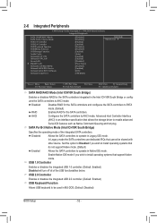
... Peripherals CMOS Setup Utility-Copyright (C) 1984-2009 Award Software Integrated Peripherals SATA RAID/AHCI Mode SATA Port0-3 Native Mode USB 1.0 Controller USB 2.0 Controller USB Keyboard Function USB Mouse Function USB Storage Function Azalia Codec Onboard H/W 1394 Onboard H/W LAN Green LAN } SMART LAN Onboard LAN Boot ROM Onboard SATA/IDE Device Onboard SATA/IDE Ctrl Mode Onboard Serial Port 1 [Disabled] [Disabled] [Enabled] [Enabled] [Disabled] [Disabled] [Enabled] [Auto] [Enabled] [Enabled] [Disabled] [Press Enter] [Disabled] [Enabled] [IDE...
... Peripherals CMOS Setup Utility-Copyright (C) 1984-2009 Award Software Integrated Peripherals SATA RAID/AHCI Mode SATA Port0-3 Native Mode USB 1.0 Controller USB 2.0 Controller USB Keyboard Function USB Mouse Function USB Storage Function Azalia Codec Onboard H/W 1394 Onboard H/W LAN Green LAN } SMART LAN Onboard LAN Boot ROM Onboard SATA/IDE Device Onboard SATA/IDE Ctrl Mode Onboard Serial Port 1 [Disabled] [Disabled] [Enabled] [Enabled] [Disabled] [Disabled] [Enabled] [Auto] [Enabled] [Enabled] [Disabled] [Press Enter] [Disabled] [Enabled] [IDE...
Manual
Page 54
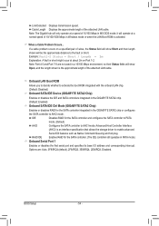
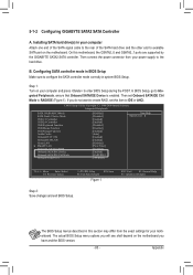
... the boot ROM integrated with the onboard LAN chip. (Default: Disabled) Onboard SATA/IDE Device (GIGABYTE SATA2 Chip) Enables or disables the IDE and SATA controllers integrated in the GIGABYTE SATA2 chip. (Default: Enabled) Onboard SATA/IDE Ctrl Mode (GIGABYTE SATA2 Chip) Enables or disables RAID for the SATA controller and configures the SATA controller to PATA mode. (Default) AHCI Configures the SATA controller to AHCI mode. Advanced Host Controller Interface (AHCI) is activated. BIOS Setup - 54 - When a Cable Problem Occurs... Link Detected Displays...
... the boot ROM integrated with the onboard LAN chip. (Default: Disabled) Onboard SATA/IDE Device (GIGABYTE SATA2 Chip) Enables or disables the IDE and SATA controllers integrated in the GIGABYTE SATA2 chip. (Default: Enabled) Onboard SATA/IDE Ctrl Mode (GIGABYTE SATA2 Chip) Enables or disables RAID for the SATA controller and configures the SATA controller to PATA mode. (Default) AHCI Configures the SATA controller to AHCI mode. Advanced Host Controller Interface (AHCI) is activated. BIOS Setup - 54 - When a Cable Problem Occurs... Link Detected Displays...
Manual
Page 58
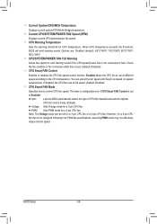
... fan connection when this occurs. (Default: Disabled) CPU Smart FAN Control Enables or disables the CPU fan speed control function. Current CPU/SYSTEM/POWER FAN Speed (RPM) Displays current CPU/system/power fan speed. This item is configurable only if CPU Smart FAN Control is set for a 4-pin CPU fan. If disabled, the CPU fan runs at different speed according to control CPU fan speed. You can be set to emit warning sound if the CPU/system/power fan is not designed following Intel PWM fan specifications, selecting PWM mode may not effectively reduce the fan speed. CPU...
... fan connection when this occurs. (Default: Disabled) CPU Smart FAN Control Enables or disables the CPU fan speed control function. Current CPU/SYSTEM/POWER FAN Speed (RPM) Displays current CPU/system/power fan speed. This item is configurable only if CPU Smart FAN Control is set for a 4-pin CPU fan. If disabled, the CPU fan runs at different speed according to control CPU fan speed. You can be set to emit warning sound if the CPU/system/power fan is not designed following Intel PWM fan specifications, selecting PWM mode may not effectively reduce the fan speed. CPU...
Manual
Page 80
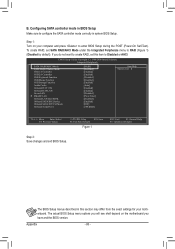
... (Disabled by default). CMOS Setup Utility-Copyright (C) 1984-2009 Award Software Integrated Peripherals SATA RAID/AHCI Mode SATA Port0-3 Native Mode USB 1.0 Controller USB 2.0 Controller USB Keyboard Function USB Mouse Function USB Storage Function Azalia Codec Onboard H/W 1394 Onboard H/W LAN Green LAN } SMART LAN Onboard LAN Boot ROM Onboard SATA/IDE Device Onboard SATA/IDE Ctrl Mode Onboard Serial Port 1 [RAID] [Disabled] [Enabled] [Enabled] [Disabled] [Disabled] [Enabled] [Auto] [Enabled] [Enabled] [Disabled] [Press Enter] [Disabled] [Enabled...
... (Disabled by default). CMOS Setup Utility-Copyright (C) 1984-2009 Award Software Integrated Peripherals SATA RAID/AHCI Mode SATA Port0-3 Native Mode USB 1.0 Controller USB 2.0 Controller USB Keyboard Function USB Mouse Function USB Storage Function Azalia Codec Onboard H/W 1394 Onboard H/W LAN Green LAN } SMART LAN Onboard LAN Boot ROM Onboard SATA/IDE Device Onboard SATA/IDE Ctrl Mode Onboard Serial Port 1 [RAID] [Disabled] [Enabled] [Enabled] [Disabled] [Disabled] [Enabled] [Auto] [Enabled] [Enabled] [Disabled] [Press Enter] [Disabled] [Enabled...
Manual
Page 85
... SATA hard drive and the other end to IDE or AHCI. CMOS Setup Utility-Copyright (C) 1984-2009 Award Software Integrated Peripherals SATA RAID/AHCI Mode SATA Port0-3 Native Mode USB 1.0 Controller USB 2.0 Controller USB Keyboard Function USB Mouse Function USB Storage Function Azalia Codec Onboard H/W 1394 Onboard H/W LAN Green LAN } SMART LAN Onboard LAN Boot ROM Onboard SATA/IDE Device Onboard SATA/IDE Ctrl Mode Onboard Serial Port 1 [Disabled] [Disabled] [Enabled] [Enabled] [Disabled] [Disabled] [Enabled] [Auto] [Enabled] [Enabled...
... SATA hard drive and the other end to IDE or AHCI. CMOS Setup Utility-Copyright (C) 1984-2009 Award Software Integrated Peripherals SATA RAID/AHCI Mode SATA Port0-3 Native Mode USB 1.0 Controller USB 2.0 Controller USB Keyboard Function USB Mouse Function USB Storage Function Azalia Codec Onboard H/W 1394 Onboard H/W LAN Green LAN } SMART LAN Onboard LAN Boot ROM Onboard SATA/IDE Device Onboard SATA/IDE Ctrl Mode Onboard Serial Port 1 [Disabled] [Disabled] [Enabled] [Enabled] [Disabled] [Disabled] [Enabled] [Auto] [Enabled] [Enabled...
Manual
Page 86
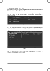
... to the installation of the GIGABYTE SATA2 RAID BIOS utility (Figure 3), use the up or down arrow key to enter the GIGABYTE SATA2 RAID BIOS utility. PCIE-to-SATAII/IDE RAID Controller BIOS v1.06.78 [ Main Menu ] Create RAID Disk Drive Delete RAID Disk Drive Revert HDD to Non-RAID Solve Mirror Conflict Rebuild Mirror Drive Save And Exit Setup Exit Without Saving [ Hard Disk Drive List ] Model Name HDD0: ST3120026AS HDD1: ST3120026AS Capacity 120 GB 120 GB Type/Status Non-RAID Non-RAID [ RAID Disk Drive List ] [fgTAB]-Switch Window [hi...
... to the installation of the GIGABYTE SATA2 RAID BIOS utility (Figure 3), use the up or down arrow key to enter the GIGABYTE SATA2 RAID BIOS utility. PCIE-to-SATAII/IDE RAID Controller BIOS v1.06.78 [ Main Menu ] Create RAID Disk Drive Delete RAID Disk Drive Revert HDD to Non-RAID Solve Mirror Conflict Rebuild Mirror Drive Save And Exit Setup Exit Without Saving [ Hard Disk Drive List ] Model Name HDD0: ST3120026AS HDD1: ST3120026AS Capacity 120 GB 120 GB Type/Status Non-RAID Non-RAID [ RAID Disk Drive List ] [fgTAB]-Switch Window [hi...
Manual
Page 91
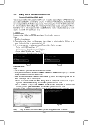
..., type (Figure 2): (Note) A:\>copy d:\bootdrv\gsata\32bit\*.* Figure 1 In Windows mode: Figure 2 Steps: 1: Use an alternative system and insert the motherboard driver disk. 2: From your optical drive is /are configured to RAID/AHCI mode, you need to install the SATA controller driver during the Windows setup process. Steps: 1: Boot from the menu. Select the controller driver by pressing the corresponding letter from the startup disk. 2: Remove the startup disk and insert the prepared floppy disk and the motherboard driver disk...
..., type (Figure 2): (Note) A:\>copy d:\bootdrv\gsata\32bit\*.* Figure 1 In Windows mode: Figure 2 Steps: 1: Use an alternative system and insert the motherboard driver disk. 2: From your optical drive is /are configured to RAID/AHCI mode, you need to install the SATA controller driver during the Windows setup process. Steps: 1: Boot from the menu. Select the controller driver by pressing the corresponding letter from the startup disk. 2: Remove the startup disk and insert the prepared floppy disk and the motherboard driver disk...

Manual
Page 93
... proceed with Windows, using a device support disk provided by an adapter manufacturer. After the driver installation, you want from the following list, or press ESC to return to the previous screen. (Windows XP/2003) RAID/AHCI Driver for GIGABYTE GBB36X Controller (Windows 2000) RAID Driver for GIGABYTE GBB363 Controller (Windows 2000) AHCI Driver for GIGABYTE GBB363 Controller (Windows 2000) RAID Driver for GIGABYTE GBB360 Controller ENTER=Select F3=Exit Figure 3 Step 3: On the next screen, press to continue the driver installation. Appendix Windows Setup You have...
... proceed with Windows, using a device support disk provided by an adapter manufacturer. After the driver installation, you want from the following list, or press ESC to return to the previous screen. (Windows XP/2003) RAID/AHCI Driver for GIGABYTE GBB36X Controller (Windows 2000) RAID Driver for GIGABYTE GBB363 Controller (Windows 2000) AHCI Driver for GIGABYTE GBB363 Controller (Windows 2000) RAID Driver for GIGABYTE GBB360 Controller ENTER=Select F3=Exit Figure 3 Step 3: On the next screen, press to continue the driver installation. Appendix Windows Setup You have...
Manual
Page 109
... jumper, refer to the Support&Downloads\Motherboards\FAQ page on our website and search for your board doesn't have turned my speaker to install. A: The following Award BIOS beep code descriptions may help you identify possible computer problems. (For reference only.) 1 short: System boots successfully 1 long, 3 short: Keyboard error 2 short: CMOS setting error 1 long, 9 short: BIOS ROM error 1 long, 1 short: Memory or motherboard error Continuous long beeps: Graphics card not inserted properly 1 long, 2 short: Monitor or graphics card error Continuous short beeps: Power error...
... jumper, refer to the Support&Downloads\Motherboards\FAQ page on our website and search for your board doesn't have turned my speaker to install. A: The following Award BIOS beep code descriptions may help you identify possible computer problems. (For reference only.) 1 short: System boots successfully 1 long, 3 short: Keyboard error 2 short: CMOS setting error 1 long, 9 short: BIOS ROM error 1 long, 1 short: Memory or motherboard error Continuous long beeps: Graphics card not inserted properly 1 long, 2 short: Monitor or graphics card error Continuous short beeps: Power error...


