Manual
Page 1
GA-EP45T-UD3R/ GA-EP45T-UD3 LGA775 socket motherboard for Intel® CoreTM processor family/ Intel® Pentium® processor family/Intel® Celeron® processor family User's Manual Rev. 1002 12ME-EP45TUD3R-1002R
GA-EP45T-UD3R/ GA-EP45T-UD3 LGA775 socket motherboard for Intel® CoreTM processor family/ Intel® Pentium® processor family/Intel® Celeron® processor family User's Manual Rev. 1002 12ME-EP45TUD3R-1002R
Manual
Page 2
Motherboard GA-EP45T-UD3R/GA-EP45T-UD3 Oct. 2, 2008 Motherboard GA-EP45T-UD3R/ GA-EP45T-UD3 Oct. 2, 2008
Motherboard GA-EP45T-UD3R/GA-EP45T-UD3 Oct. 2, 2008 Motherboard GA-EP45T-UD3R/ GA-EP45T-UD3 Oct. 2, 2008
Manual
Page 3
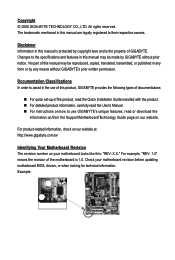
...GIGA-BYTE TECHNOLOGY CO., LTD. Documentation Classifications In order to assist in the use GIGABYTE's unique features, read the User's Manual. For instructions on your motherboard revision before updating motherboard BIOS, drivers, or when looking for technical information. For product-related information, check... on our website at: http://www.gigabyte.com.tw Identifying Your Motherboard Revision The revision number on how to the specifications and features in this : "REV: X.X." The trademarks ...
...GIGA-BYTE TECHNOLOGY CO., LTD. Documentation Classifications In order to assist in the use GIGABYTE's unique features, read the User's Manual. For instructions on your motherboard revision before updating motherboard BIOS, drivers, or when looking for technical information. For product-related information, check... on our website at: http://www.gigabyte.com.tw Identifying Your Motherboard Revision The revision number on how to the specifications and features in this : "REV: X.X." The trademarks ...
Manual
Page 4
Table of Contents Box Contents ...6 Optional Items...6 GA-EP45T-UD3R/UD3 Motherboard Layout 7 Block Diagram...8 Chapter 1 Hardware Installation 9 1-1 Installation Precautions 9 1-2 Product Specifications 10 1-3 Installing the CPU and CPU Cooler 13 1-3-1 Installing the CPU 13 1-3-2 Installing the CPU ...
Table of Contents Box Contents ...6 Optional Items...6 GA-EP45T-UD3R/UD3 Motherboard Layout 7 Block Diagram...8 Chapter 1 Hardware Installation 9 1-1 Installation Precautions 9 1-2 Product Specifications 10 1-3 Installing the CPU and CPU Cooler 13 1-3-1 Installing the CPU 13 1-3-2 Installing the CPU ...
Manual
Page 6
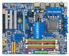
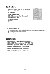
... and one floppy disk drive cable Four SATA 3Gb/s cables One SATA bracket I/O Shield Only for GA-EP45T-UD3R. • The box contents above are subject to change without notice. • The motherboard image is for reference only and the actual items shall depend on product package you obtain. Optional Items 2-port...
... and one floppy disk drive cable Four SATA 3Gb/s cables One SATA bracket I/O Shield Only for GA-EP45T-UD3R. • The box contents above are subject to change without notice. • The motherboard image is for reference only and the actual items shall depend on product package you obtain. Optional Items 2-port...
Manual
Page 7
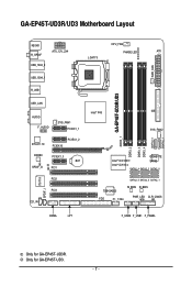
GA-EP45T-UD3R/UD3 DDR3_1 DDR3_2 DDR3_3 DDR3_4 GSATA2_0 GSATA2_1 GA-EP45T-UD3R/UD3 Motherboard Layout KB_MS CPU_FAN R_SPDIF ATX_12V_2X4 LGA775 PHASE LED ATX USB_1394_2 PWR_FAN USB_1394_1 R_USB USB_LAN AUDIO F_AUDIO SYS_FAN1 PCIEX1_1 RTL8111C PCIEX16 PCIEX1_2 CODEC PCIEX1_3 BAT SPDIF_O CI PCI1 IT8718 SPDIF_I PCI2 PCI3 CD_IN Intel® P45 IDE SYS_FAN2 GIGABYTE Intel® ICH10R SATA2 Intel...
GA-EP45T-UD3R/UD3 DDR3_1 DDR3_2 DDR3_3 DDR3_4 GSATA2_0 GSATA2_1 GA-EP45T-UD3R/UD3 Motherboard Layout KB_MS CPU_FAN R_SPDIF ATX_12V_2X4 LGA775 PHASE LED ATX USB_1394_2 PWR_FAN USB_1394_1 R_USB USB_LAN AUDIO F_AUDIO SYS_FAN1 PCIEX1_1 RTL8111C PCIEX16 PCIEX1_2 CODEC PCIEX1_3 BAT SPDIF_O CI PCI1 IT8718 SPDIF_I PCI2 PCI3 CD_IN Intel® P45 IDE SYS_FAN2 GIGABYTE Intel® ICH10R SATA2 Intel...

Manual
Page 9
... best to the use of the product, please consult a certified computer technician. - 9 - Chapter 1 Hardware Installation 1-1 Installation Precautions The motherboard contains numerous delicate electronic circuits and components which can lead to damage to system components as well as physical harm to the user. •...required for warranty validation. • Always remove theAC power by your hardware components are connected. • To prevent damage to the motherboard, do not have an ESD wrist strap, keep your hands dry and first touch a metal object to eliminate static electricity. &#...
... best to the use of the product, please consult a certified computer technician. - 9 - Chapter 1 Hardware Installation 1-1 Installation Precautions The motherboard contains numerous delicate electronic circuits and components which can lead to damage to system components as well as physical harm to the user. •...required for warranty validation. • Always remove theAC power by your hardware components are connected. • To prevent damage to the motherboard, do not have an ESD wrist strap, keep your hands dry and first touch a metal object to eliminate static electricity. &#...
Manual
Page 10
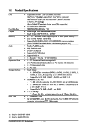
... 1394a bracket connected to the internal IEEE 1394a header) Only for GA-EP45T-UD3R. Only for SATA RAID 0, RAID 1, RAID 5 and RAID 10 GIGABYTE SATA2 chip: - 1 x IDE connector supporting ATA-133/100/66/33 ...and up to 2 IDE devices - 2 x SATA 3Gb/s connectors (GSATA2_0, GSATA2_1) supporting up to 2 SATA 3Gb/s devices - Support for SATA RAID 0, RAID 1 and JBOD iTE IT8718 chip: - 1 x floppy disk drive connector supporting up to 6 SA TA 3Gb/s devices - GA-EP45T-UD3R/UD3 Motherboard...
... 1394a bracket connected to the internal IEEE 1394a header) Only for GA-EP45T-UD3R. Only for SATA RAID 0, RAID 1, RAID 5 and RAID 10 GIGABYTE SATA2 chip: - 1 x IDE connector supporting ATA-133/100/66/33 ...and up to 2 IDE devices - 2 x SATA 3Gb/s connectors (GSATA2_0, GSATA2_1) supporting up to 2 SATA 3Gb/s devices - Support for SATA RAID 0, RAID 1 and JBOD iTE IT8718 chip: - 1 x floppy disk drive connector supporting up to 6 SA TA 3Gb/s devices - GA-EP45T-UD3R/UD3 Motherboard...
Manual
Page 12
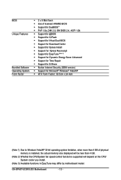
GA-EP45T-UD3R/UD3 Motherboard - 12 - BIOS Unique Features Bundled Software Operating System Form Factor 2 x 8 Mbit flash Use of licensed AWARD BIOS Support for DualBIOSTM PnP 1.... CPU/System fan speed control function is supported will depend on the CPU/ System cooler you install. (Note 3) Available functions in EasyTune may differ by motherboard model.
GA-EP45T-UD3R/UD3 Motherboard - 12 - BIOS Unique Features Bundled Software Operating System Form Factor 2 x 8 Mbit flash Use of licensed AWARD BIOS Support for DualBIOSTM PnP 1.... CPU/System fan speed control function is supported will depend on the CPU/ System cooler you install. (Note 3) Available functions in EasyTune may differ by motherboard model.
Manual
Page 13
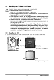
mended that the motherboard supports the CPU. (Go to GIGABYTE's website for the peripherals. Locate the alignment keys on the motherboard CPU socket and the notches on the CPU - 13 - Hardware Installation It is not installed, otherwise overheating and damage of the CPU may locate the ...
mended that the motherboard supports the CPU. (Go to GIGABYTE's website for the peripherals. Locate the alignment keys on the motherboard CPU socket and the notches on the CPU - 13 - Hardware Installation It is not installed, otherwise overheating and damage of the CPU may locate the ...
Manual
Page 14
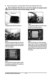
... Step 4: Hold the CPU with the socket alignment keys) and gently insert the CPU into position. B. Follow the steps below to the CPU. GA-EP45T-UD3R/UD3 Motherboard - 14 - Before installing the CPU, make sure to turn off the computer and unplug the power cord from the load plate. (To protect the..., always replace the protective socket cover when the CPU is properly inserted, replace the load plate and push the CPU socket lever back into the motherboard CPU socket. CPU Socket Lever Step 1: Completely raise the CPU socket lever. Step 2: Lift the metal load plate from the CPU socket. (...
... Step 4: Hold the CPU with the socket alignment keys) and gently insert the CPU into position. B. Follow the steps below to the CPU. GA-EP45T-UD3R/UD3 Motherboard - 14 - Before installing the CPU, make sure to turn off the computer and unplug the power cord from the load plate. (To protect the..., always replace the protective socket cover when the CPU is properly inserted, replace the load plate and push the CPU socket lever back into the motherboard CPU socket. CPU Socket Lever Step 1: Completely raise the CPU socket lever. Step 2: Lift the metal load plate from the CPU socket. (...
Manual
Page 15
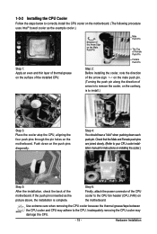
...contrary, is to your CPU cooler installation manual for instructions on installing the cooler.) Step 5: After the installation, check the back of the motherboard. Use extreme care when removing the CPU cooler because the thermal grease/tape between the CPU cooler and CPU may damage the CPU. - ...15 - Inadequately removing the CPU cooler may adhere to the CPU fan header (CPU_FAN) on the motherboard. Hardware Installation Step 6: Finally, attach the power connector of the installed CPU. Push down each push pin. Step 4: You should hear a "click...
...contrary, is to your CPU cooler installation manual for instructions on installing the cooler.) Step 5: After the installation, check the back of the motherboard. Use extreme care when removing the CPU cooler because the thermal grease/tape between the CPU cooler and CPU may damage the CPU. - ...15 - Inadequately removing the CPU cooler may adhere to the CPU fan header (CPU_FAN) on the motherboard. Hardware Installation Step 6: Finally, attach the power connector of the installed CPU. Push down each push pin. Step 4: You should hear a "click...
Manual
Page 16
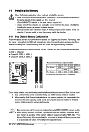
...DDR3_2 DDR3_3 DDR3_4 Due to insert the memory, switch the direction. 1-4-1 Dual Channel Memory Configuration This motherboard provides four DDR3 memory sockets and supports Dual Channel Technology. GA-EP45T-UD3R/UD3 Motherboard - 16 - 1-4 Installing the Memory Read the following guidelines before you are unable to chipset limitation...capacity, brand, speed, and chips be used . (Go to GIGABYTE's website for optimum performance. • Each channel can be enabled if only one DDR3 memory module is recommended that the motherboard supports the memory. DS/SS - - Intel ® Flex ...
...DDR3_2 DDR3_3 DDR3_4 Due to insert the memory, switch the direction. 1-4-1 Dual Channel Memory Configuration This motherboard provides four DDR3 memory sockets and supports Dual Channel Technology. GA-EP45T-UD3R/UD3 Motherboard - 16 - 1-4 Installing the Memory Read the following guidelines before you are unable to chipset limitation...capacity, brand, speed, and chips be used . (Go to GIGABYTE's website for optimum performance. • Each channel can be enabled if only one DDR3 memory module is recommended that the motherboard supports the memory. DS/SS - - Intel ® Flex ...
Manual
Page 17
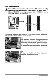
... - Hardware Installation Step 1: Note the orientation of the memory, push down on the top edge of the memory module. Place the memory module on this motherboard. 1-4-2 Installing a Memory Before installing a memory module , make sure to turn off the computer and unplug the power cord from the power outlet to prevent damage...
... - Hardware Installation Step 1: Note the orientation of the memory, push down on the top edge of the memory module. Place the memory module on this motherboard. 1-4-2 Installing a Memory Before installing a memory module , make sure to turn off the computer and unplug the power cord from the power outlet to prevent damage...
Manual
Page 18
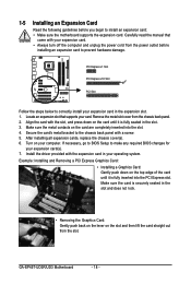
... Graphics Card: • Installing a Graphics Card: Gently push down on the card are completely inserted into the PCI Express slot. GA-EP45T-UD3R/UD3 Motherboard - 18 - PCI Express x1 Slot PCI Express x16 Slot PCI Slot Follow the steps below to correctly install your card. Make ...Installing an Expansion Card Read the following guidelines before installing an expansion card to install an expansion card: • Make sure the motherboard supports the expansion card. Remove the metal slot cover from the power outlet before you begin to prevent hardware damage. If necessary, ...
... Graphics Card: • Installing a Graphics Card: Gently push down on the card are completely inserted into the PCI Express slot. GA-EP45T-UD3R/UD3 Motherboard - 18 - PCI Express x1 Slot PCI Express x16 Slot PCI Slot Follow the steps below to correctly install your card. Make ...Installing an Expansion Card Read the following guidelines before installing an expansion card to install an expansion card: • Make sure the motherboard supports the expansion card. Remove the metal slot cover from the power outlet before you begin to prevent hardware damage. If necessary, ...
Manual
Page 19
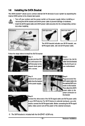
... the SA TA bracket: Step 1: Locate one free PCI slot and secure the SATA bracket to the power supply. nector on your motherboard. Step 2: Connect the SA TA cable from the bracket SATA signal cable into the corresponding connectors when installing. Before connecting the SATA signal... prevent damage to hardware. • Insert the SATA signal cable and SATA power cable securely into to the chassis back panel with the GA-EP45T -UD3R only. - 19 - the external SATA con- 1-6 Installing the SATA Bracket The SATA bracket allows you only need to connect the...
... the SA TA bracket: Step 1: Locate one free PCI slot and secure the SATA bracket to the power supply. nector on your motherboard. Step 2: Connect the SA TA cable from the bracket SATA signal cable into the corresponding connectors when installing. Before connecting the SATA signal... prevent damage to hardware. • Insert the SATA signal cable and SATA power cable securely into to the chassis back panel with the GA-EP45T -UD3R only. - 19 - the external SATA con- 1-6 Installing the SATA Bracket The SATA bracket allows you only need to connect the...
Manual
Page 20
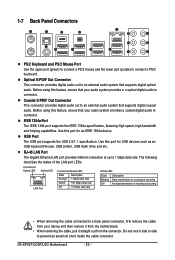
...from the connector. Before using this port for an IEEE 1394a device. Use this feature, ensure that your device and then remove it from the motherboard. • When removing the cable, pull it side to side to a back panel connector, first remove the cable from your audio system ... USB devices such as an USB keyboard/mouse, USB printer, USB flash drive and etc. The following describes the states of the LAN port LEDs. GA-EP45T-UD3R/UD3 Motherboard - 20 - 1-7 Back Panel Connectors PS/2 Keyboard and PS/2 Mouse Port Use the upper port (green) to connect a PS/2 mouse and the...
...from the connector. Before using this port for an IEEE 1394a device. Use this feature, ensure that your device and then remove it from the motherboard. • When removing the cable, pull it side to side to a back panel connector, first remove the cable from your audio system ... USB devices such as an USB keyboard/mouse, USB printer, USB flash drive and etc. The following describes the states of the LAN port LEDs. GA-EP45T-UD3R/UD3 Motherboard - 20 - 1-7 Back Panel Connectors PS/2 Keyboard and PS/2 Mouse Port Use the upper port (green) to connect a PS/2 mouse and the...
Manual
Page 22
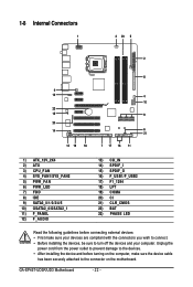
... compliant with the connectors you wish to connect. • Before installing the devices, be sure to the connector on the computer, make sure your computer. GA-EP45T-UD3R/UD3 Motherboard - 22 - 1-8 Internal Connectors 1 3 23 5 2 4 12 22 15 20 14 13 19 18 8 4 10 9 6 21 7 17 16 11 1) ATX_12V_2X4 2) ATX 3) CPU_FAN 4) SYS_FAN1/SYS_FAN2 5) PWR_FAN 6) PWR_LED...) F_USB1/F_USB2 17) F1_1394 18) LPT 19) COMA 20) CI 21) CLR_CMOS 22) BAT 23) PHASE LED Read the following guidelines before turning on the motherboard.
... compliant with the connectors you wish to connect. • Before installing the devices, be sure to the connector on the computer, make sure your computer. GA-EP45T-UD3R/UD3 Motherboard - 22 - 1-8 Internal Connectors 1 3 23 5 2 4 12 22 15 20 14 13 19 18 8 4 10 9 6 21 7 17 16 11 1) ATX_12V_2X4 2) ATX 3) CPU_FAN 4) SYS_FAN1/SYS_FAN2 5) PWR_FAN 6) PWR_LED...) F_USB1/F_USB2 17) F1_1394 18) LPT 19) COMA 20) CI 21) CLR_CMOS 22) BAT 23) PHASE LED Read the following guidelines before turning on the motherboard.
Manual
Page 23
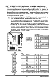
... using a power supply providing a 2x4 12V and power connector, remove the protective covers from the 12V power connector and the main power connector on the motherboard. Hardware Installation 1/2) ATX_12V_2X4/ATX (2x4 12V Power Connector and 2x12 Main Power Connector) With the use of a power supply providing a 2x4 12V power connector is... all devices are properly installed. The power connector possesses a foolproof design. If the 12V power connector is turned off and all the components on the motherboard.
... using a power supply providing a 2x4 12V and power connector, remove the protective covers from the 12V power connector and the main power connector on the motherboard. Hardware Installation 1/2) ATX_12V_2X4/ATX (2x4 12V Power Connector and 2x12 Main Power Connector) With the use of a power supply providing a 2x4 12V power connector is... all devices are properly installed. The power connector possesses a foolproof design. If the 12V power connector is turned off and all the components on the motherboard.
Manual
Page 24
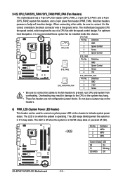
...connect fan cables to the fan headers to indicate system power status. Definition 1 MPD+ 1 2 MPD- 3 MPD- 3/4/5) CPU_FAN/SYS_FAN1/SYS_FAN2/PWR_FAN (Fan Headers) The motherboard has a 4-pin CPU fan header (CPU_FAN), a 3-pin (SYS_FAN1) and a 4-pin (SYS_FAN2) system fan headers, and a 3-pin power fan header (PWR_FAN). .... CPU_FAN: Pin No. Overheating may result in S1 sleep state. System Status LED S0 On S1 Blinking S3/S4/S5 Off GA-EP45T-UD3R/UD3 Motherboard - 24 - The LED is off when the system is operating. When connecting a fan cable, be installed inside the chassis....
...connect fan cables to the fan headers to indicate system power status. Definition 1 MPD+ 1 2 MPD- 3 MPD- 3/4/5) CPU_FAN/SYS_FAN1/SYS_FAN2/PWR_FAN (Fan Headers) The motherboard has a 4-pin CPU fan header (CPU_FAN), a 3-pin (SYS_FAN1) and a 4-pin (SYS_FAN2) system fan headers, and a 3-pin power fan header (PWR_FAN). .... CPU_FAN: Pin No. Overheating may result in S1 sleep state. System Status LED S0 On S1 Blinking S3/S4/S5 Off GA-EP45T-UD3R/UD3 Motherboard - 24 - The LED is off when the system is operating. When connecting a fan cable, be installed inside the chassis....


