
Manual
Page 9
...; Before turning on the power, make sure they are connected tightly and securely. • When handling the motherboard, avoid touching any installation steps or have a problem related to wear an electrostatic discharge (ESD) wrist strap when handling electronic components such as a motherboard, CPU or memory.
...; Before turning on the power, make sure they are connected tightly and securely. • When handling the motherboard, avoid touching any installation steps or have a problem related to wear an electrostatic discharge (ESD) wrist strap when handling electronic components such as a motherboard, CPU or memory.
Manual
Page 28
The LED is off (S5). • PW (Power Switch, Red): Connects to indicate the problem. The system reports system startup status by chassis. If a problem is in S1 sleep state. A front panel module mainly consists of f your chassis front panel module to the hard drive activity...; MSG (Message/Power/Sleep LED, Yellow): System Status LED Connects to the pin assignments below. One single short beep will be heard if no problem is operating. Refer to Chapter 5, "Troubleshooting," for more information). • SPEAK (Speaker, Orange): Connects to the reset switch on when the hard...
The LED is off (S5). • PW (Power Switch, Red): Connects to indicate the problem. The system reports system startup status by chassis. If a problem is in S1 sleep state. A front panel module mainly consists of f your chassis front panel module to the hard drive activity...; MSG (Message/Power/Sleep LED, Yellow): System Status LED Connects to the pin assignments below. One single short beep will be heard if no problem is operating. Refer to Chapter 5, "Troubleshooting," for more information). • SPEAK (Speaker, Orange): Connects to the reset switch on when the hard...
Manual
Page 35
.... • It is potentially risky, if you can press + in the main menu of the BIOS Setup program. To flash the BIOS, do not encounter problems using the Q-Flash and @BIOS utilities, refer to Chapter 4, "BIOS Update Utilities." • Because BIOS flashing is recommended that allows the user to modify basic.... BIOS includes a BIOS Setup program that you not alter the default settings (unless you not flash the BIOS. To upgrade the BIOS, use either the GIGABYTE Q-Flash or @BIOS utility . • Q-Flash allows the user to clear the CMOS values.) - 35 - For instructions on .
.... • It is potentially risky, if you can press + in the main menu of the BIOS Setup program. To flash the BIOS, do not encounter problems using the Q-Flash and @BIOS utilities, refer to Chapter 4, "BIOS Update Utilities." • Because BIOS flashing is recommended that allows the user to modify basic.... BIOS includes a BIOS Setup program that you not alter the default settings (unless you not flash the BIOS. To upgrade the BIOS, use either the GIGABYTE Q-Flash or @BIOS utility . • Q-Flash allows the user to clear the CMOS values.) - 35 - For instructions on .
Manual
Page 53
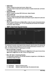
... LAN Cable Is Functioning Normally... This feature will show Open and the Length fields show 0m, as shown in the figure above. If no cable problem is connected or not. If no LAN cable is attached to the motherboard, the Status fields of all four pairs of wires will detect cabling...
... LAN Cable Is Functioning Normally... This feature will show Open and the Length fields show 0m, as shown in the figure above. If no cable problem is connected or not. If no LAN cable is attached to the motherboard, the Status fields of all four pairs of wires will detect cabling...
Manual
Page 54
...onboard LAN chip. (Default: Disabled) Onboard SATA/IDE Device (GIGABYTE SATA2 Chip) Enables or disables the IDE and SA TA controllers integrated in the GIGABYTE SA TA 2 chip. (Default: Enabled) Onboard SATA/IDE Ctrl Mode (GIGABYTE SATA2 Chip) Enables or disables RAID for the SATA controller. ...fault or short. GA-EP45T-UD3R/UD3 Motherboard - 54 - RAID/IDE Enables RAID for the SA TA controller integrated in the GIGABYTE SA TA 2 chip or configures the SATA controller to enable advanced Serial ATA features such as Native Command Queuing and hot plug. If a cable problem occurs on Part...
...onboard LAN chip. (Default: Disabled) Onboard SATA/IDE Device (GIGABYTE SATA2 Chip) Enables or disables the IDE and SA TA controllers integrated in the GIGABYTE SA TA 2 chip. (Default: Enabled) Onboard SATA/IDE Ctrl Mode (GIGABYTE SATA2 Chip) Enables or disables RAID for the SATA controller. ...fault or short. GA-EP45T-UD3R/UD3 Motherboard - 54 - RAID/IDE Enables RAID for the SA TA controller integrated in the GIGABYTE SA TA 2 chip or configures the SATA controller to enable advanced Serial ATA features such as Native Command Queuing and hot plug. If a cable problem occurs on Part...
Manual
Page 111
... screwdriver to touch the positive and negative terminals of standby power after the computer shuts down and that's why the light is still on GIGABYTE's website. Q: What do I still get a weak sound even though I clear the CMOS values? A: Some advanced options are some ... to the maximum volume? Q: Why do the beeps emitted during the POST. A: The following Award BIOS beep code descriptions may help you identify possible computer problems. (For reference only.) 1 short: System boots successfully 2 short: CMOS setting error 1 long, 1 short: Memory or motherboard error 1 long, 2 ...
... screwdriver to touch the positive and negative terminals of standby power after the computer shuts down and that's why the light is still on GIGABYTE's website. Q: What do I still get a weak sound even though I clear the CMOS values? A: Some advanced options are some ... to the maximum volume? Q: Why do the beeps emitted during the POST. A: The following Award BIOS beep code descriptions may help you identify possible computer problems. (For reference only.) 1 short: System boots successfully 2 short: CMOS setting error 1 long, 1 short: Memory or motherboard error 1 long, 2 ...
Manual
Page 112
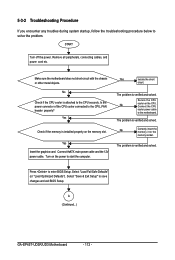
... CPU cooler power cable to enter BIOS Setup. Yes Check if the memory is verified and solved. The problem is verified and solved. START Turn off the power. Secure the CPU No cooler on the memory slot....-circuit with the chassis or other metal objects. Turn on the power to the CPU_FAN header properly? The problem is installed properly on the CPU. Remove all peripherals, connecting cables, and power cord etc. Is the power... Defaults"). Select "Save & Exit Setup" to save changes and exit BIOS Setup. A (Continued...) GA-EP45T-UD3R/UD3 Motherboard - 112 -
... CPU cooler power cable to enter BIOS Setup. Yes Check if the memory is verified and solved. The problem is verified and solved. START Turn off the power. Secure the CPU No cooler on the memory slot....-circuit with the chassis or other metal objects. Turn on the power to the CPU_FAN header properly? The problem is installed properly on the CPU. Remove all peripherals, connecting cables, and power cord etc. Is the power... Defaults"). Select "Save & Exit Setup" to save changes and exit BIOS Setup. A (Continued...) GA-EP45T-UD3R/UD3 Motherboard - 112 -
Manual
Page 113
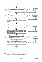
...go to the Support\Technical Service Zone page to see if the device works successfully). Yes Reinstall the operating system. The problem is verified and solved. The problem is verified and solved. Select "Load Fail-Safe Defaults" (or "Load Optimized Defaults"). A When the computer is turned... on your monitor. Appendix Yes Turn off the computer and connect the IDE/SATA devices. The problem is the CPU cooler running? END If the procedure above is display on , is verified and solved. No The graphics card, expansion ...
...go to the Support\Technical Service Zone page to see if the device works successfully). Yes Reinstall the operating system. The problem is verified and solved. The problem is verified and solved. Select "Load Fail-Safe Defaults" (or "Load Optimized Defaults"). A When the computer is turned... on your monitor. Appendix Yes Turn off the computer and connect the IDE/SATA devices. The problem is the CPU cooler running? END If the procedure above is display on , is verified and solved. No The graphics card, expansion ...


