Manual
Page 3
... your motherboard revision before updating motherboard BIOS, drivers, or when looking for technical information. Check your motherboard looks like this manual may be reproduced, copied, translated, transmitted, or published in this manual may be made by any means without prior notice. Example: No part of GIGABYTE. Documentation Classifications In order to assist...
... your motherboard revision before updating motherboard BIOS, drivers, or when looking for technical information. Check your motherboard looks like this manual may be reproduced, copied, translated, transmitted, or published in this manual may be made by any means without prior notice. Example: No part of GIGABYTE. Documentation Classifications In order to assist...
Manual
Page 4
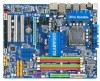
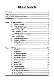
Table of Contents Box Contents ...6 Optional Items...6 GA-EP45T-UD3R/UD3 Motherboard Layout 7 Block Diagram...8 Chapter 1 Hardware Installation 9 1-1 Installation Precautions 9 1-2 Product Specifications 10 1-3 Installing the CPU and CPU Cooler...Installing the SATA Bracket 19 1-7 Back Panel Connectors 20 1-8 Internal Connectors 22 Chapter 2 BIOS Setup 35 2-1 Startup Screen 36 2-2 The Main Menu 37 2-3 MB Intelligent Tweaker(M.I.T 39 2-4 Standard CMOS Features 47 2-5 Advanced BIOS Features 49 2-6 Integrated Peripherals 52 2-7 Power Management Setup 56 2-8 PnP/PCI Configurations 58...
Table of Contents Box Contents ...6 Optional Items...6 GA-EP45T-UD3R/UD3 Motherboard Layout 7 Block Diagram...8 Chapter 1 Hardware Installation 9 1-1 Installation Precautions 9 1-2 Product Specifications 10 1-3 Installing the CPU and CPU Cooler...Installing the SATA Bracket 19 1-7 Back Panel Connectors 20 1-8 Internal Connectors 22 Chapter 2 BIOS Setup 35 2-1 Startup Screen 36 2-2 The Main Menu 37 2-3 MB Intelligent Tweaker(M.I.T 39 2-4 Standard CMOS Features 47 2-5 Advanced BIOS Features 49 2-6 Integrated Peripherals 52 2-7 Power Management Setup 56 2-8 PnP/PCI Configurations 58...
Manual
Page 5
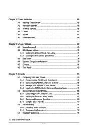
...Utilities 74 4-2-1 Updating the BIOS with the Q-Flash Utility 74 4-2-2 Updating the BIOS with the @BIOS Utility 77 4-3 EasyTune 6...78 4-4 Dynamic Energy Saver Advanced 79 4-5 Q-Share ...81 4-6 Time Repair ...82 Chapter 5 Appendix ...83 5-1 Configuring SATA Hard Drive(s 83 5-1-1 Configuring Intel ICH10R SATA Controllers 83 5-1-2 Configuring GIGABYTE SATA2 SATA Controller 89 5-1-3... 108 5-2-4 Using the Sound Recorder 110 5-3 Troubleshooting 111 5-3-1 Frequently Asked Questions 111 5-3-2 Troubleshooting Procedure 112 5-4 Regulatory Statements 114 Only for GA-EP45T-UD3R. - 5 -
...Utilities 74 4-2-1 Updating the BIOS with the Q-Flash Utility 74 4-2-2 Updating the BIOS with the @BIOS Utility 77 4-3 EasyTune 6...78 4-4 Dynamic Energy Saver Advanced 79 4-5 Q-Share ...81 4-6 Time Repair ...82 Chapter 5 Appendix ...83 5-1 Configuring SATA Hard Drive(s 83 5-1-1 Configuring Intel ICH10R SATA Controllers 83 5-1-2 Configuring GIGABYTE SATA2 SATA Controller 89 5-1-3... 108 5-2-4 Using the Sound Recorder 110 5-3 Troubleshooting 111 5-3-1 Frequently Asked Questions 111 5-3-2 Troubleshooting Procedure 112 5-4 Regulatory Statements 114 Only for GA-EP45T-UD3R. - 5 -
Manual
Page 8
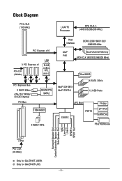
... CLK (100 MHz) x1 x1 x1 LAN RJ45 RTL 8111C x1 PCI Express Bus 2 SATA 3Gb/s ATA-133/100/66/ 33 IDE Channel PCI Bus GIGABYTE SATA2 TSB43AB23 3 IEEE 1394a Host Interface DDR3 2200/1600/1333/ 1066/800 MHz Intel® P45 Dual Channel Memory MCH CLK (400/333/266/200... Dual BIOS 6 SATA 3Gb/s 12 USB Ports CODEC LPC Bus IT8718 Floppy LPT Port COM Port PS/2 KB/Mouse Surround Speaker Out Center/Subwoofer Speaker Out Side Speaker Out MIC Line-Out Line-In SPDIF In SPDIF Out 3 PCI PCI CLK (33 MHz) Only for GA-EP45T-UD3R. Only for GA-EP45T-UD3. - 8 -
... CLK (100 MHz) x1 x1 x1 LAN RJ45 RTL 8111C x1 PCI Express Bus 2 SATA 3Gb/s ATA-133/100/66/ 33 IDE Channel PCI Bus GIGABYTE SATA2 TSB43AB23 3 IEEE 1394a Host Interface DDR3 2200/1600/1333/ 1066/800 MHz Intel® P45 Dual Channel Memory MCH CLK (400/333/266/200... Dual BIOS 6 SATA 3Gb/s 12 USB Ports CODEC LPC Bus IT8718 Floppy LPT Port COM Port PS/2 KB/Mouse Surround Speaker Out Center/Subwoofer Speaker Out Side Speaker Out MIC Line-Out Line-In SPDIF In SPDIF Out 3 PCI PCI CLK (33 MHz) Only for GA-EP45T-UD3R. Only for GA-EP45T-UD3. - 8 -
Manual
Page 12
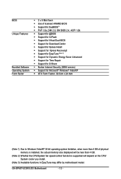
GA-EP45T-UD3R/UD3 Motherboard - 12 - BIOS Unique Features Bundled Software Operating System Form Factor 2 x 8 Mbit flash Use of licensed AWARD BIOS Support for DualBIOSTM PnP 1.0a, DMI 2.0, SM BIOS 2.4, ACPI 1.0b Support for @BIOS Support for Q-Flash Support for Virtual Dual BIOS Support for Download Center Support for Xpress...
GA-EP45T-UD3R/UD3 Motherboard - 12 - BIOS Unique Features Bundled Software Operating System Form Factor 2 x 8 Mbit flash Use of licensed AWARD BIOS Support for DualBIOSTM PnP 1.0a, DMI 2.0, SM BIOS 2.4, ACPI 1.0b Support for @BIOS Support for Q-Flash Support for Virtual Dual BIOS Support for Download Center Support for Xpress...
Manual
Page 16
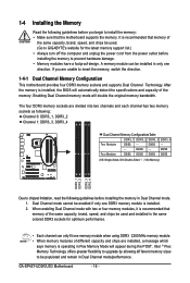
...limitation, read the following guidelines before installing the memory in only one DDR3 memory module is installed, the BIOS will double the original memory bandwidth. After the memory is installed. 2. Dual Channel mode cannot be populated... in the same colored DDR3 sockets for optimum performance. • Each channel can be used . (Go to GIGABYTE's website for the latest memory support list.) • Always turn off the computer and unplug the power cord ...and chips be used and installed in Dual Channel mode/performance. DS/SS - - - - GA-EP45T-UD3R/UD3 Motherboard - 16 -
...limitation, read the following guidelines before installing the memory in only one DDR3 memory module is installed, the BIOS will double the original memory bandwidth. After the memory is installed. 2. Dual Channel mode cannot be populated... in the same colored DDR3 sockets for optimum performance. • Each channel can be used . (Go to GIGABYTE's website for the latest memory support list.) • Always turn off the computer and unplug the power cord ...and chips be used and installed in Dual Channel mode/performance. DS/SS - - - - GA-EP45T-UD3R/UD3 Motherboard - 16 -
Manual
Page 18
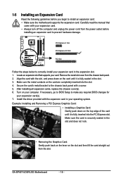
... your expansion card(s). 7. Turn on the slot and then lift the card straight out from the slot. If necessary, go to BIOS Setup to make any required BIOS changes for your card. GA-EP45T-UD3R/UD3 Motherboard - 18 - Make sure the card is fully inserted into the slot. 4. Locate an expansion slot that came with...
... your expansion card(s). 7. Turn on the slot and then lift the card straight out from the slot. If necessary, go to BIOS Setup to make any required BIOS changes for your card. GA-EP45T-UD3R/UD3 Motherboard - 18 - Make sure the card is fully inserted into the slot. 4. Locate an expansion slot that came with...
Manual
Page 28
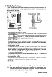
...(Message/Power/Sleep LED, Yellow): System Status LED Connects to the power switch on the chassis front panel. The LED is detected, the BIOS may differ by issuing a beep code. Refer to Chapter 5, "Troubleshooting," for more information). • SPEAK (Speaker, Orange): Connects to... the pin assignments below. When connecting your system using the power switch (refer to Chapter 2, "BIOS Setup," "Power Management Setup," for information about beep codes. • HD (Hard Drive Activity LED, Blue) Connects to indicate the problem. If...
...(Message/Power/Sleep LED, Yellow): System Status LED Connects to the power switch on the chassis front panel. The LED is detected, the BIOS may differ by issuing a beep code. Refer to Chapter 5, "Troubleshooting," for more information). • SPEAK (Speaker, Orange): Connects to... the pin assignments below. When connecting your system using the power switch (refer to Chapter 2, "BIOS Setup," "Power Management Setup," for information about beep codes. • HD (Hard Drive Activity LED, Blue) Connects to indicate the problem. If...
Manual
Page 33
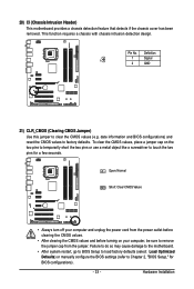
...that detects if the chassis cover has been removed. This function requires a chassis with chassis intrusion detection design. Hardware Installation date information and BIOS configurations) and reset the CMOS values to remove the jumper cap from the power outlet before clearing the CMOS values. • After ...CMOS values and before turning on the two pins to temporarily short the two pins or use a metal object like a screwdriver to Chapter 2, "BIOS Setup," for a few seconds. Open: Normal Short: Clear CMOS Values • Always turn off your computer and unplug the power cord from ...
...that detects if the chassis cover has been removed. This function requires a chassis with chassis intrusion detection design. Hardware Installation date information and BIOS configurations) and reset the CMOS values to remove the jumper cap from the power outlet before clearing the CMOS values. • After ...CMOS values and before turning on the two pins to temporarily short the two pins or use a metal object like a screwdriver to Chapter 2, "BIOS Setup," for a few seconds. Open: Normal Short: Clear CMOS Values • Always turn off your computer and unplug the power cord from ...
Manual
Page 34
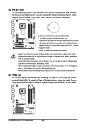
... the battery: 1. The higher the CPU loading, the more details. 22) BAT (BATTERY) The battery provides power to keep the values (such as BIOS configurations, date, and time information) in the CMOS when the computer is replaced with an equivalent one minute. (Or use a metal object like a ... of the positive side (+) and the negative side (-) of the battery (the positive side should face up). • Used batteries must be lost. GA-EP45T-UD3R/UD3 Motherboard - 34 - Plug in the power cord and restart your computer. • Always turn off your computer and unplug the power cord before...
... the battery: 1. The higher the CPU loading, the more details. 22) BAT (BATTERY) The battery provides power to keep the values (such as BIOS configurations, date, and time information) in the CMOS when the computer is replaced with an equivalent one minute. (Or use a metal object like a ... of the positive side (+) and the negative side (-) of the battery (the positive side should face up). • Used batteries must be lost. GA-EP45T-UD3R/UD3 Motherboard - 34 - Plug in the power cord and restart your computer. • Always turn off your computer and unplug the power cord before...
Manual
Page 35
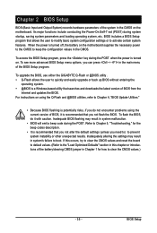
... it is recommended that you not alter the default settings (unless you need to) to prevent system instability or other unexpected results. To upgrade the BIOS, use either the GIGABYTE Q-Flash or @BIOS utility . • Q-Flash allows the user to activate certain system features. To see more advanced...
... it is recommended that you not alter the default settings (unless you need to) to prevent system instability or other unexpected results. To upgrade the BIOS, use either the GIGABYTE Q-Flash or @BIOS utility . • Q-Flash allows the user to activate certain system features. To see more advanced...
Manual
Page 36
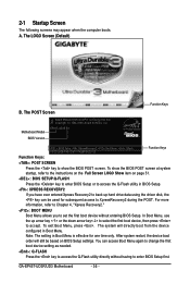
... screen at system startup, refer to the instructions on the Full Screen LOGO Show item on BIOS Setup settings. GA-EP45T-UD3R/UD3 Motherboard - 36 - Note: The setting in Boot Menu. A. In Boot Menu, use the up hard drive data using the driver disk, the key can ...access Boot Menu again to change the first boot device setting as needed. : Q-FLASH Press the key to access the Q-Flash utility directly without entering BIOS...
... screen at system startup, refer to the instructions on the Full Screen LOGO Show item on BIOS Setup settings. GA-EP45T-UD3R/UD3 Motherboard - 36 - Note: The setting in Boot Menu. A. In Boot Menu, use the up hard drive data using the driver disk, the key can ...access Boot Menu again to change the first boot device setting as needed. : Q-FLASH Press the key to access the Q-Flash utility directly without entering BIOS...
Manual
Page 37
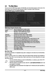
...Main Menu. Use arrow keys to move among the items and press to accept or enter a sub-menu. (Sample BIOS Version: GA-EP45T-UD3R E2) CMOS Setup Utility-Copyright (C) 1984-2008 Award Software MB Intelligent Tweaker(M.I.T.) Standard CMOS Features Advanced... BIOS Features Integrated Peripherals Power Management Setup PnP/PCI Configurations PC Health Status Load Fail-...
...Main Menu. Use arrow keys to move among the items and press to accept or enter a sub-menu. (Sample BIOS Version: GA-EP45T-UD3R E2) CMOS Setup Utility-Copyright (C) 1984-2008 Award Software MB Intelligent Tweaker(M.I.T.) Standard CMOS Features Advanced... BIOS Features Integrated Peripherals Power Management Setup PnP/PCI Configurations PC Health Status Load Fail-...
Manual
Page 38
... Save all changes and the previous settings remain in the BIOS Setup program to the CMOS and exit BIOS Setup. (Pressing can use this menu to the system and BIOS Setup. You can also carry out this task.) GA-EP45T-UD3R/UD3 Motherboard - 38 - A supervisor password allows you to... save the current BIOS settings to 8 profiles (Profile 1-8) and name each profile. Pressing to the confirmation message will exit BIOS Setup. (Pressing can create...
... Save all changes and the previous settings remain in the BIOS Setup program to the CMOS and exit BIOS Setup. (Pressing can use this menu to the system and BIOS Setup. You can also carry out this task.) GA-EP45T-UD3R/UD3 Motherboard - 38 - A supervisor password allows you to... save the current BIOS settings to 8 profiles (Profile 1-8) and name each profile. Pressing to the confirmation message will exit BIOS Setup. (Pressing can create...
Manual
Page 39
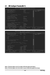
BIOS Setup 2-3 MB Intelligent Tweaker(M.I.T.) CMOS Setup Utility-Copyright (C) 1984-2008 Award Software MB Intelligent Tweaker(M.I.T.) Robust Graphics Booster CPU Clock Ratio (Note 1) Fine CPU Clock ...
BIOS Setup 2-3 MB Intelligent Tweaker(M.I.T.) CMOS Setup Utility-Copyright (C) 1984-2008 Award Software MB Intelligent Tweaker(M.I.T.) Robust Graphics Booster CPU Clock Ratio (Note 1) Fine CPU Clock ...
Manual
Page 40
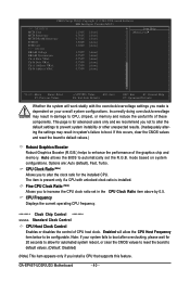
... damage to enhance the performance of the graphics chip and memory. Auto allows the BIOS to be configurable. The item is present only if a CPU with the overclock/overvoltage settings you made is dependent on system configurations. GA-EP45T-UD3R/UD3 Motherboard - 40 - If this feature. Note: If your overall system configurations. This page...
... damage to enhance the performance of the graphics chip and memory. Auto allows the BIOS to be configurable. The item is present only if a CPU with the overclock/overvoltage settings you made is dependent on system configurations. GA-EP45T-UD3R/UD3 Motherboard - 40 - If this feature. Note: If your overall system configurations. This page...
Manual
Page 41
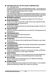
... Increases CPU frequency by 9% or 1 1% depending on CPU loading through the use of 5 preset states. Racing Increases CPU frequency by 7% or 9% depending on CPU loading. BIOS Setup C.I .A.2. (Default) Cruise Increases CPU frequency by 15% or 17% depending on CPU loading. Turbo Increases CPU frequency by 5% or 7% depending on CPU loading. As...
... Increases CPU frequency by 9% or 1 1% depending on CPU loading through the use of 5 preset states. Racing Increases CPU frequency by 7% or 9% depending on CPU loading. BIOS Setup C.I .A.2. (Default) Cruise Increases CPU frequency by 15% or 17% depending on CPU loading. Turbo Increases CPU frequency by 5% or 7% depending on CPU loading. As...
Manual
Page 42
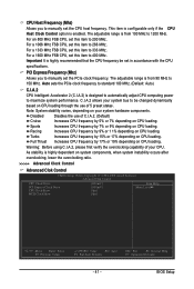
... at system bootup. Extreme Memory Profile (X.M.P.) (Note) Allows the BIOS to be configurable. PCI Express Clock Drive Allows you to the North Bridge clock. Profile2 Uses Profile 2 settings. (G)MCH Frequency Latch Allows you to set the CPU clock prior to adjust the amplitude of the memory being used; GA-EP45T-UD3R/UD3 Motherboard - 42 -
... at system bootup. Extreme Memory Profile (X.M.P.) (Note) Allows the BIOS to be configurable. PCI Express Clock Drive Allows you to the North Bridge clock. Profile2 Uses Profile 2 settings. (G)MCH Frequency Latch Allows you to set the CPU clock prior to adjust the amplitude of the memory being used; GA-EP45T-UD3R/UD3 Motherboard - 42 -
Manual
Page 43
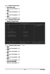
tWTR Options are : Auto (default), 1~3. ******** ESC: Exit F1: General Help F7: Optimized Defaults - 43 - Command Rate(CMD) Options are : Auto (default), 1~31. BIOS Setup >>>>> Standard Timing Control CAS Latency Time Options are : Auto (default), 1~15. tRCD Options are : Auto (default), 4~11. tRFC Options are : Auto (default), 1~15. tRP ...
tWTR Options are : Auto (default), 1~3. ******** ESC: Exit F1: General Help F7: Optimized Defaults - 43 - Command Rate(CMD) Options are : Auto (default), 1~31. BIOS Setup >>>>> Standard Timing Control CAS Latency Time Options are : Auto (default), 1~15. tRCD Options are : Auto (default), 4~11. tRFC Options are : Auto (default), 1~15. tRP ...
Manual
Page 45
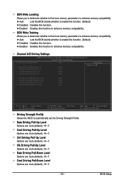
... compatibility. Data Driving Pull-Up Level Options are : Auto (default), +8~-7. Enabled Enables this function. Auto Lets the BIOS decide whether to enable this function. (Default) Disabled Disables this function to enhance memory compatibility. Enabled Enables this function.... Options are : Auto (default), +8~-7. - 45 - Cmd Driving Pull-Down Level Options are : Auto (default), +8~-7. Auto Lets the BIOS decide whether to enable this function. (Default) Disabled Disables this function to automatically set the Driving Strength Profile. Channel A/B Driving Settings CMOS...
... compatibility. Data Driving Pull-Up Level Options are : Auto (default), +8~-7. Enabled Enables this function. Auto Lets the BIOS decide whether to enable this function. (Default) Disabled Disables this function to enhance memory compatibility. Enabled Enables this function.... Options are : Auto (default), +8~-7. - 45 - Cmd Driving Pull-Down Level Options are : Auto (default), +8~-7. Auto Lets the BIOS decide whether to enable this function. (Default) Disabled Disables this function to automatically set the Driving Strength Profile. Channel A/B Driving Settings CMOS...


