
Manual
Page 1
GA-EP45-DS3P LGA775 socket motherboard for Intel® CoreTM processor family/ Intel® Pentium® processor family/Intel® Celeron® processor family User's Manual Rev. 1003 12ME-EP45DS3P-1003R
GA-EP45-DS3P LGA775 socket motherboard for Intel® CoreTM processor family/ Intel® Pentium® processor family/Intel® Celeron® processor family User's Manual Rev. 1003 12ME-EP45DS3P-1003R

Manual
Page 2
Motherboard GA-EP45-DS3P May 15, 2008 Motherboard GA-EP45-DS3P May 15, 2008
Motherboard GA-EP45-DS3P May 15, 2008 Motherboard GA-EP45-DS3P May 15, 2008
Manual
Page 3
... and features in this manual may be reproduced, copied, translated, transmitted, or published in the use GIGABYTE's unique features, read or download the information on/from the Support\Motherboard\Technology Guide page on your motherboard revision before updating motherboard BIOS, drivers, or when looking for technical information. Changes to their respective owners. No part...
... and features in this manual may be reproduced, copied, translated, transmitted, or published in the use GIGABYTE's unique features, read or download the information on/from the Support\Motherboard\Technology Guide page on your motherboard revision before updating motherboard BIOS, drivers, or when looking for technical information. Changes to their respective owners. No part...

Manual
Page 4
Table of Contents Box Contents ...6 OptionalItems ...6 GA-EP45-DS3P Motherboard Layout 7 Block Diagram ...8 Chapter 1 Hardware Installation 9 1-1 Installation Precautions 9 1-2 Product Specifications 10 1-3 Installing the CPU and CPU Cooler 13 1-3-1 Installing the CPU 13 1-3-2 Installing the CPU ...
Table of Contents Box Contents ...6 OptionalItems ...6 GA-EP45-DS3P Motherboard Layout 7 Block Diagram ...8 Chapter 1 Hardware Installation 9 1-1 Installation Precautions 9 1-2 Product Specifications 10 1-3 Installing the CPU and CPU Cooler 13 1-3-1 Installing the CPU 13 1-3-2 Installing the CPU ...
Manual
Page 6
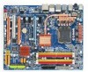
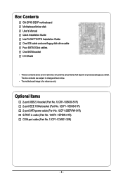
...power cable (Part No. 12CF1-2SERPW-01R) S/PDIF in cable (Part No. 12CR1-1SPDIN-01R) COM port cable (Part No. 12CF1-1CM001-32R) - 6 - Box Contents GA-EP45-DS3P motherboard Motherboard driver disk User's Manual Quick Installation Guide Intel® LGA775 CPU Installation Guide One IDE cable and one floppy disk drive cable Four SATA 3Gb.../s cables One SATA bracket I/O Shield • The box contents above are subject to change without notice. • The motherboard image is for reference only and the actual items shall depend on product package you obtain.
...power cable (Part No. 12CF1-2SERPW-01R) S/PDIF in cable (Part No. 12CR1-1SPDIN-01R) COM port cable (Part No. 12CF1-1CM001-32R) - 6 - Box Contents GA-EP45-DS3P motherboard Motherboard driver disk User's Manual Quick Installation Guide Intel® LGA775 CPU Installation Guide One IDE cable and one floppy disk drive cable Four SATA 3Gb.../s cables One SATA bracket I/O Shield • The box contents above are subject to change without notice. • The motherboard image is for reference only and the actual items shall depend on product package you obtain.

Manual
Page 7
GA-EP45-DS3P Motherboard Layout KB_MS SYS_FAN1 CPU_LED R_SPDIF USB_1394_2 ATX_12V_2X USB_1394_1 LGA775 CPU_FAN PHASE LED ACPI_LED (S0/1/3/4/5_LED) PWR_FAN GA-EP45-DS3P DIMM_LED ATX USB_LAN2 USB_LAN1 RTL8111C F_AUDIO AUDIO PCIEX1_1 PE1_LED Intel® P45 RTL8111C PCIEX16_1 NB_FAN CODEC PCIEX1_2 M_BIOS PCIEX1_3 B_BIOS BAT FDD PE_LED DDR2_1 DDR2_2 ...
GA-EP45-DS3P Motherboard Layout KB_MS SYS_FAN1 CPU_LED R_SPDIF USB_1394_2 ATX_12V_2X USB_1394_1 LGA775 CPU_FAN PHASE LED ACPI_LED (S0/1/3/4/5_LED) PWR_FAN GA-EP45-DS3P DIMM_LED ATX USB_LAN2 USB_LAN1 RTL8111C F_AUDIO AUDIO PCIEX1_1 PE1_LED Intel® P45 RTL8111C PCIEX16_1 NB_FAN CODEC PCIEX1_2 M_BIOS PCIEX1_3 B_BIOS BAT FDD PE_LED DDR2_1 DDR2_2 ...

Manual
Page 9
...components as well as a result of electrostatic discharge (ESD). If you are connected tightly and securely. • When handling the motherboard, avoid touching any installation steps or have it on top of an antistatic pad or within an electrostatic shielding container. • ...Before unplugging the power supply cable from the power outlet before installing or removing the motherboard or other hardware components. • When connecting hardware components to the internal connectors on the computer power during the installation ...
...components as well as a result of electrostatic discharge (ESD). If you are connected tightly and securely. • When handling the motherboard, avoid touching any installation steps or have it on top of an antistatic pad or within an electrostatic shielding container. • ...Before unplugging the power supply cable from the power outlet before installing or removing the motherboard or other hardware components. • When connecting hardware components to the internal connectors on the computer power during the installation ...

Manual
Page 10
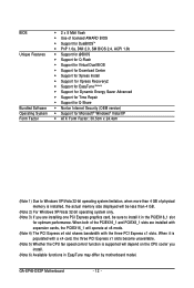
...system memory (Note 1) Š Dual channel memory architecture Š Support for DDR2 1200/1066/800/667 MHz memory modules (Go to GIGABYTE's website for the latest memory support list.) Š Realtek ALC889A codec Š High Definition Audio Š 2/4/5.1/7.1-channel Š Support... PCI Express x1 slots Š 1 x PCI slot Š South Bridge: - 6 x SATA 3Gb/s connectors supporting up to the internal IEEE 1394a header) GA-EP45-DS3P Motherboard - 10 - TSB43AB23 chip Š Up to 3 IEEE 1394a ports (2 on the back panel, 1 via the IEEE 1394a bracket connected to 1 floppy disk drive &#...
...system memory (Note 1) Š Dual channel memory architecture Š Support for DDR2 1200/1066/800/667 MHz memory modules (Go to GIGABYTE's website for the latest memory support list.) Š Realtek ALC889A codec Š High Definition Audio Š 2/4/5.1/7.1-channel Š Support... PCI Express x1 slots Š 1 x PCI slot Š South Bridge: - 6 x SATA 3Gb/s connectors supporting up to the internal IEEE 1394a header) GA-EP45-DS3P Motherboard - 10 - TSB43AB23 chip Š Up to 3 IEEE 1394a ports (2 on the back panel, 1 via the IEEE 1394a bracket connected to 1 floppy disk drive &#...
Manual
Page 12
... than 4 GB. (Note 2) For Windows XP/Vista 32-bit operating system only. (Note 3) If you install. (Note 6) Available functions in EasyTune may differ by motherboard model. GA-EP45-DS3P Motherboard - 12 - When both of physical memory is supported will operate at x8 mode. (Note 4) The PCI Express x4 slot shares bandwidth with expansion cards, the...
... than 4 GB. (Note 2) For Windows XP/Vista 32-bit operating system only. (Note 3) If you install. (Note 6) Available functions in EasyTune may differ by motherboard model. GA-EP45-DS3P Motherboard - 12 - When both of physical memory is supported will operate at x8 mode. (Note 4) The PCI Express x4 slot shares bandwidth with expansion cards, the...
Manual
Page 13
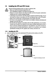
...hardware specifications including the CPU, graphics card, memory, hard drive, etc. 1-3-1 Installing the CPU A. Locate the alignment keys on the motherboard CPU socket and the notches on the computer if the CPU cooler is not recom- The CPU cannot be set the frequency beyond ...you may occur. • Set the CPU host frequency in accordance with the CPU specifications. Hardware Installation mended that the motherboard supports the CPU. (Go to GIGABYTE's website for the peripherals. 1-3 Installing the CPU and CPU Cooler Read the following guidelines before installing the CPU to prevent...
...hardware specifications including the CPU, graphics card, memory, hard drive, etc. 1-3-1 Installing the CPU A. Locate the alignment keys on the motherboard CPU socket and the notches on the computer if the CPU cooler is not recom- The CPU cannot be set the frequency beyond ...you may occur. • Set the CPU host frequency in accordance with the CPU specifications. Hardware Installation mended that the motherboard supports the CPU. (Go to GIGABYTE's website for the peripherals. 1-3 Installing the CPU and CPU Cooler Read the following guidelines before installing the CPU to prevent...

Manual
Page 14
... 2: Remove the protective socket cover. Step 5: Once the CPU is properly inserted, replace the load plate and push the CPU socket lever back into the motherboard CPU socket. Step 4: Hold the CPU with the socket alignment keys) and gently insert the CPU into position. Align the CPU pin one marking (triangle... the metal load plate on the CPU socket. CPU Socket Lever Step 1: Completely raise the CPU socket lever. Follow the steps below to the CPU. B. GA-EP45-DS3P Motherboard - 14 -
... 2: Remove the protective socket cover. Step 5: Once the CPU is properly inserted, replace the load plate and push the CPU socket lever back into the motherboard CPU socket. Step 4: Hold the CPU with the socket alignment keys) and gently insert the CPU into position. Align the CPU pin one marking (triangle... the metal load plate on the CPU socket. CPU Socket Lever Step 1: Completely raise the CPU socket lever. Follow the steps below to the CPU. B. GA-EP45-DS3P Motherboard - 14 -

Manual
Page 15
... CPU cooler and CPU may damage the CPU. - 15 - Inadequately removing the CPU cooler may adhere to the CPU fan header (CPU_FAN) on the motherboard. Check that the Male and Female push pins are joined closely. (Refer to install.) Step 3: Place the cooler atop the CPU, aligning the four ...push pins through the pin holes on the motherboard. If the push pin is inserted as the example cooler.) Step 1: Apply an even and thin layer of thermal grease on installing the cooler.) Step...
... CPU cooler and CPU may damage the CPU. - 15 - Inadequately removing the CPU cooler may adhere to the CPU fan header (CPU_FAN) on the motherboard. Check that the Male and Female push pins are joined closely. (Refer to install.) Step 3: Place the cooler atop the CPU, aligning the four ...push pins through the pin holes on the motherboard. If the push pin is inserted as the example cooler.) Step 1: Apply an even and thin layer of thermal grease on installing the cooler.) Step...

Manual
Page 16
... - - - - Intel® Flex Memory Technology offers greater flexibility to upgrade by allowing different memory sizes to be used . (Go to GIGABYTE's website for optimum performance. DS/SS - - DS/SS Four Modules DS/SS DS/SS DS/SS DS/SS (SS=Single-Sided, DS=...following: Channel 0: DDR2_1, DDR2_2 Channel 1: DDR2_3, DDR2_4 Dual Channel Memory Configurations Table DDR2_1 DDR2_2 DDR2_3 DDR2_4 Two Modules DS/SS - - GA-EP45-DS3P Motherboard - 16 - If you begin to prevent hardware damage. • Memory modules have a foolproof design. Enabling Dual Channel memory mode will...
... - - - - Intel® Flex Memory Technology offers greater flexibility to upgrade by allowing different memory sizes to be used . (Go to GIGABYTE's website for optimum performance. DS/SS - - DS/SS Four Modules DS/SS DS/SS DS/SS DS/SS (SS=Single-Sided, DS=...following: Channel 0: DDR2_1, DDR2_2 Channel 1: DDR2_3, DDR2_4 Dual Channel Memory Configurations Table DDR2_1 DDR2_2 DDR2_3 DDR2_4 Two Modules DS/SS - - GA-EP45-DS3P Motherboard - 16 - If you begin to prevent hardware damage. • Memory modules have a foolproof design. Enabling Dual Channel memory mode will...

Manual
Page 17
... memory modules in the picture on the left, place your fingers on the top edge of the memory module. Place the memory module on this motherboard. Step 1: Note the orientation of the memory, push down on the memory and insert it can only fit in one direction. Hardware Installation Spread the...
... memory modules in the picture on the left, place your fingers on the top edge of the memory module. Place the memory module on this motherboard. Step 1: Note the orientation of the memory, push down on the memory and insert it can only fit in one direction. Hardware Installation Spread the...

Manual
Page 18
... and Removing a PCI Express Graphics Card: • Installing a Graphics Card: Gently push down on the card are completely inserted into the PCI Express x16 slot. GA-EP45-DS3P Motherboard - 18 - • Removing the Card from the slot. 1-5 Installing an Expansion Card Read the following guidelines before installing an expansion card to the chassis back... Slot PCI Express x16 Slot PCI Express x8/x4 Slot PCI Slot Follow the steps below to install an expansion card: • Make sure the motherboard supports the expansion card. Align the card with a screw. 5.
... and Removing a PCI Express Graphics Card: • Installing a Graphics Card: Gently push down on the card are completely inserted into the PCI Express x16 slot. GA-EP45-DS3P Motherboard - 18 - • Removing the Card from the slot. 1-5 Installing an Expansion Card Read the following guidelines before installing an expansion card to the chassis back... Slot PCI Express x16 Slot PCI Express x8/x4 Slot PCI Slot Follow the steps below to install an expansion card: • Make sure the motherboard supports the expansion card. Align the card with a screw. 5.

Manual
Page 19
... to install the SATA bracket: Step 1: Locate one free PCI slot and secure the SATA bracket to connect the SATA signal cable. nector on your motherboard. Step 2: Connect the SATA cable from the bracket SATA signal cable into the corresponding connectors when installing. For SATA device in external enclosure, you to...
... to install the SATA bracket: Step 1: Locate one free PCI slot and secure the SATA bracket to connect the SATA signal cable. nector on your motherboard. Step 2: Connect the SATA cable from the bracket SATA signal cable into the corresponding connectors when installing. For SATA device in external enclosure, you to...

Manual
Page 20
... up to connect a PS/2 keyboard. Before using this feature, ensure that your audio system provides an optical digital audio in connector. GA-EP45-DS3P Motherboard - 20 - Optical S/PDIF Out Connector This connector provides digital audio out to an external audio system that supports digital optical audio. Coaxial...connector provides digital audio out to an external audio system that supports digital coaxial audio. Do not rock it straight out from the motherboard. • When removing the cable, pull it side to side to a back panel connector, first remove the cable from ...
... up to connect a PS/2 keyboard. Before using this feature, ensure that your audio system provides an optical digital audio in connector. GA-EP45-DS3P Motherboard - 20 - Optical S/PDIF Out Connector This connector provides digital audio out to an external audio system that supports digital optical audio. Coaxial...connector provides digital audio out to an external audio system that supports digital coaxial audio. Do not rock it straight out from the motherboard. • When removing the cable, pull it side to side to a back panel connector, first remove the cable from ...

Manual
Page 22
... a component (including CPU and memory) or a device (including PCI and PCIe cards and IDE/SATA devices) works abnormally. Power Switch Reset Switch Clearing CMOS Switch GA-EP45-DS3P Motherboard - 22 - CPU Memory PCIe x8/x16 PCIe x1/x4 PCI IDE SATA ACPI LEDs The 4 embedded ACPI LEDs indicate the system power status (S0, S1...
... a component (including CPU and memory) or a device (including PCI and PCIe cards and IDE/SATA devices) works abnormally. Power Switch Reset Switch Clearing CMOS Switch GA-EP45-DS3P Motherboard - 22 - CPU Memory PCIe x8/x16 PCIe x1/x4 PCI IDE SATA ACPI LEDs The 4 embedded ACPI LEDs indicate the system power status (S0, S1...

Manual
Page 23
..., make sure your devices are compliant with the connectors you wish to connect. • Before installing the devices, be sure to the connector on the motherboard. - 23 -
..., make sure your devices are compliant with the connectors you wish to connect. • Before installing the devices, be sure to the connector on the motherboard. - 23 -

Manual
Page 24
.../Off) GND GND GND -5V +5V +5V +5V (Only for 2x12 pin ATX) GND (Only for 2x4 pin 12V) 7 +12V 8 +12V 12 24 1 13 ATX GA-EP45-DS3P Motherboard ATX : Pin No. 1 2 3 4 5 6 7 8 9 10 11 12 Definition Pin No. 3.3V 13 3.3V 14 GND 15 +5V 16 GND 17 +5V 18 GND ... power supply providing a 2x4 12V and a 2x12 power connector, remove the protective covers from the 12V power connector and the main power connector on the motherboard. 1/2) ATX_12V_2X/ATX (2x4 12V Power Connector and 2x12 Main Power Connector) With the use of a power supply providing a 2x4 12V power connector is ...
.../Off) GND GND GND -5V +5V +5V +5V (Only for 2x12 pin ATX) GND (Only for 2x4 pin 12V) 7 +12V 8 +12V 12 24 1 13 ATX GA-EP45-DS3P Motherboard ATX : Pin No. 1 2 3 4 5 6 7 8 9 10 11 12 Definition Pin No. 3.3V 13 3.3V 14 GND 15 +5V 16 GND 17 +5V 18 GND ... power supply providing a 2x4 12V and a 2x12 power connector, remove the protective covers from the 12V power connector and the main power connector on the motherboard. 1/2) ATX_12V_2X/ATX (2x4 12V Power Connector and 2x12 Main Power Connector) With the use of a power supply providing a 2x4 12V power connector is ...


