Manual
Page 4
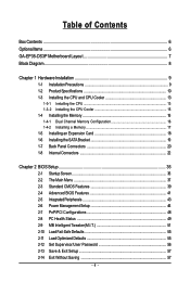
......6 GA-EP35-DS3P Motherboard Layout 7 Block Diagram...8 Chapter 1 Hardware Installation 9 1-1 Installation Precautions 9 1-2 Product Specifications 10 1-3 Installing the CPU and CPU Cooler 13 1-3-1 Installing the CPU 13 1-3-2 Installing the CPU Cooler 15 1-4 Installing the Memory 16 1-4-1 Dual Channel Memory Configuration 16 1-4-2 Installing a Memory 17 1-5 Installing an Expansion Card 18 1-6 Installing the SATA Bracket 19 1-7 Back Panel Connectors 20 1-8 Internal Connectors 22 Chapter 2 BIOS Setup 35 2-1 Startup Screen 36 2-2 The Main Menu 37 2-3 Standard CMOS Features...
......6 GA-EP35-DS3P Motherboard Layout 7 Block Diagram...8 Chapter 1 Hardware Installation 9 1-1 Installation Precautions 9 1-2 Product Specifications 10 1-3 Installing the CPU and CPU Cooler 13 1-3-1 Installing the CPU 13 1-3-2 Installing the CPU Cooler 15 1-4 Installing the Memory 16 1-4-1 Dual Channel Memory Configuration 16 1-4-2 Installing a Memory 17 1-5 Installing an Expansion Card 18 1-6 Installing the SATA Bracket 19 1-7 Back Panel Connectors 20 1-8 Internal Connectors 22 Chapter 2 BIOS Setup 35 2-1 Startup Screen 36 2-2 The Main Menu 37 2-3 Standard CMOS Features...
Manual
Page 10
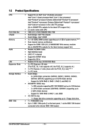
... latest CPU support list.) Š L2 cache varies with the PCIE_16_2 slot) (Note 2) Š 2 x PCI slots Š South Bridge: - 6 x SATA 3Gb/s connectors (SATAII0, SATAII1, SATAII2, SATAII3, SATAII4, SATAII5) supporting up to 8 GB of system memory (Note 1) Š Dual channel memory architecture Š Support for DDR2 1200 (O.C.)/1066/800/667 MHz memory modules (Go to the internal IEEE 1394 header) GA-EP35-DS3P Motherboard - 10 - the PCIE_16_2 supports x4.) Š 3 x PCI Express x1 slots (share with CPU...
... latest CPU support list.) Š L2 cache varies with the PCIE_16_2 slot) (Note 2) Š 2 x PCI slots Š South Bridge: - 6 x SATA 3Gb/s connectors (SATAII0, SATAII1, SATAII2, SATAII3, SATAII4, SATAII5) supporting up to 8 GB of system memory (Note 1) Š Dual channel memory architecture Š Support for DDR2 1200 (O.C.)/1066/800/667 MHz memory modules (Go to the internal IEEE 1394 header) GA-EP35-DS3P Motherboard - 10 - the PCIE_16_2 supports x4.) Š 3 x PCI Express x1 slots (share with CPU...
Manual
Page 12
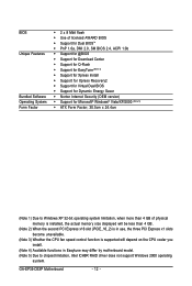
... physical memory is installed, the actual memory size displayed will be less than 4 GB. (Note 2) When the second PCI Express x16 slot (PCIE_16_2) is in use, the three PCI Express x1 slots become unavailable. (Note 3) Whether the CPU fan speed control function is supported will depend on the CPU cooler you install. (Note 4) Available functions in Easytune may differ by motherboard model. (Note 5) Due to chipset limitation, Intel ICH9R RAID driver does not support Windows 2000...
... physical memory is installed, the actual memory size displayed will be less than 4 GB. (Note 2) When the second PCI Express x16 slot (PCIE_16_2) is in use, the three PCI Express x1 slots become unavailable. (Note 3) Whether the CPU fan speed control function is supported will depend on the CPU cooler you install. (Note 4) Available functions in Easytune may differ by motherboard model. (Note 5) Due to chipset limitation, Intel ICH9R RAID driver does not support Windows 2000...
Manual
Page 16
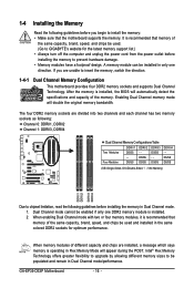
... memory support list.) • Always turn off the computer and unplug the power cord from the power outlet before installing the memory to prevent hardware damage. • Memory modules have a foolproof design. When enabling Dual Channel mode with two or four memory modules, it is installed. 2. GA-EP35-DS3P Motherboard - 16 - Enabling Dual Channel memory mode will appear during the POST. DS/SS - - Intel® Flex Memory Technology offers greater flexibility to upgrade by allowing different memory sizes to be installed...
... memory support list.) • Always turn off the computer and unplug the power cord from the power outlet before installing the memory to prevent hardware damage. • Memory modules have a foolproof design. When enabling Dual Channel mode with two or four memory modules, it is installed. 2. GA-EP35-DS3P Motherboard - 16 - Enabling Dual Channel memory mode will appear during the POST. DS/SS - - Intel® Flex Memory Technology offers greater flexibility to upgrade by allowing different memory sizes to be installed...
Manual
Page 18
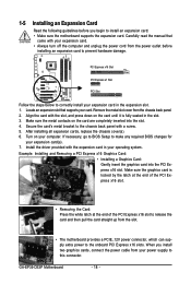
... graphics cards, connect the power cable from your expansion card(s). 7. If necessary, go to BIOS Setup to make any required BIOS changes for your power supply to this connector. Remove the metal slot cover from the slot. • The motherboard provides a PCIE_12V power connector, which can supply extra power to the onboard PCI Express x16 slots. 1-5 Installing an Expansion Card Read the following guidelines before installing an expansion card to prevent hardware damage. After installing all expansion cards, replace the chassis cover(s). 6. Install the driver...
... graphics cards, connect the power cable from your expansion card(s). 7. If necessary, go to BIOS Setup to make any required BIOS changes for your power supply to this connector. Remove the metal slot cover from the slot. • The motherboard provides a PCIE_12V power connector, which can supply extra power to the onboard PCI Express x16 slots. 1-5 Installing an Expansion Card Read the following guidelines before installing an expansion card to prevent hardware damage. After installing all expansion cards, replace the chassis cover(s). 6. Install the driver...
Manual
Page 25
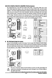
...not configuration jumper blocks. A red power connector wire indicates a positive connection and requires a +12V voltage. Definition 1 1 GND 2 +12V 3 NC • Be sure to connect fan cables to the fan headers to this header. When connecting a fan cable, be installed inside the chassis. Overheating may hang. • These fan headers are designed with color-coded power connector wires. For optimum heat dissipation, it in the correct orientation. 5/6/7) CPU_FAN/SYS_FAN1/SYS_FAN2/PWR_FAN (Fan Headers) The motherboard has a 4-pin CPU fan header (CPU_FAN), a 3-pin...
...not configuration jumper blocks. A red power connector wire indicates a positive connection and requires a +12V voltage. Definition 1 1 GND 2 +12V 3 NC • Be sure to connect fan cables to the fan headers to this header. When connecting a fan cable, be installed inside the chassis. Overheating may hang. • These fan headers are designed with color-coded power connector wires. For optimum heat dissipation, it in the correct orientation. 5/6/7) CPU_FAN/SYS_FAN1/SYS_FAN2/PWR_FAN (Fan Headers) The motherboard has a 4-pin CPU fan header (CPU_FAN), a 3-pin...
Manual
Page 41
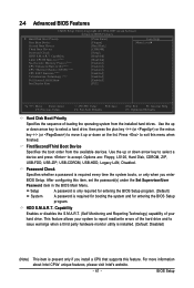
... - Options are: Floppy, LS120, Hard Disk, CDROM, ZIP, USB-FDD, USB-ZIP, USB-CDROM, USB-HDD, Legacy LAN, Disabled. Password Check Specifies whether a password is required for booting the system and for entering the BIOS Setup program. (Default) A password is required every time the system boots, or only when you install a CPU that supports this feature. First/Second/Third Boot Device Specifies the boot order from the installed hard drives. Capability Enables or disables the S.M.A.R.T. (Self Monitoring and Reporting Technology) capability of the hard drive and...
... - Options are: Floppy, LS120, Hard Disk, CDROM, ZIP, USB-FDD, USB-ZIP, USB-CDROM, USB-HDD, Legacy LAN, Disabled. Password Check Specifies whether a password is required for booting the system and for entering the BIOS Setup program. (Default) A password is required every time the system boots, or only when you install a CPU that supports this feature. First/Second/Third Boot Device Specifies the boot order from the installed hard drives. Capability Enables or disables the S.M.A.R.T. (Self Monitoring and Reporting Technology) capability of the hard drive and...
Manual
Page 42
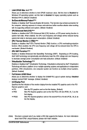
... to Disabled for legacy operating system such as multiple virtual systems. (Default: Enabled) Full Screen LOGO Show Allows you install a CPU that supports this item to decrease power consumption. (Default: Enabled) CPU Thermal Monitor 2 (TM2) (Note) Enables or disables Intel® CPU Thermal Monitor (TM2) function, a CPU overheating protection function. With virtualization, one computer system can dynamically and effectively lower the CPU voltage and core frequency to display the GIGABYTE Logo at system startup. Limit CPUID Max. Set...
... to Disabled for legacy operating system such as multiple virtual systems. (Default: Enabled) Full Screen LOGO Show Allows you install a CPU that supports this item to decrease power consumption. (Default: Enabled) CPU Thermal Monitor 2 (TM2) (Note) Enables or disables Intel® CPU Thermal Monitor (TM2) function, a CPU overheating protection function. With virtualization, one computer system can dynamically and effectively lower the CPU voltage and core frequency to display the GIGABYTE Logo at system startup. Limit CPUID Max. Set...
Manual
Page 43
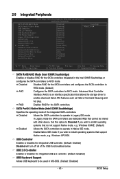
... SATA controllers. Windows XP/2000. 2-5 Integrated Peripherals CMOS Setup Utility-Copyright (C) 1984-2007 Award Software Integrated Peripherals SATA RAID/AHCI Mode SATA Port0-3 Native Mode USB Controller USB 2.0 Controller USB Keyboard Support USB Mouse Support Legacy USB storage detect Azalia Codec Onboard H/W 1394 Onboard H/W LAN ` SMART LAN Onboard LAN Boot ROM Onboard SATA/IDE Device Onboard SATA/IDE Ctrl Mode Onboard Serial Port 1 Onboard Parallel Port Parallel Port Mode [Disabled] [Disabled] [Enabled] [Enabled] [Disabled] [Disabled] [Enabled] [Auto] [Enabled] [Enabled...
... SATA controllers. Windows XP/2000. 2-5 Integrated Peripherals CMOS Setup Utility-Copyright (C) 1984-2007 Award Software Integrated Peripherals SATA RAID/AHCI Mode SATA Port0-3 Native Mode USB Controller USB 2.0 Controller USB Keyboard Support USB Mouse Support Legacy USB storage detect Azalia Codec Onboard H/W 1394 Onboard H/W LAN ` SMART LAN Onboard LAN Boot ROM Onboard SATA/IDE Device Onboard SATA/IDE Ctrl Mode Onboard Serial Port 1 Onboard Parallel Port Parallel Port Mode [Disabled] [Disabled] [Enabled] [Enabled] [Disabled] [Disabled] [Enabled] [Auto] [Enabled] [Enabled...
Manual
Page 44
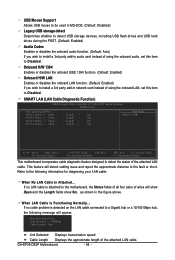
... LAN cable connected to a Gigabit hub or a 10/100 Mbps hub, the following information for diagnosing your LAN cable: When No LAN Cable Is Attached... USB Mouse Support Allows USB mouse to be used in MS-DOS. (Default: Disabled) Legacy USB storage detect Determines whether to detect USB storage devices, including USB flash drives and USB hard drives during the POST. (Default: Enabled) Azalia Codec Enables or disables the onboard audio function. (Default: Auto) If you wish to install a 3rd party add-in network card instead of using...
... LAN cable connected to a Gigabit hub or a 10/100 Mbps hub, the following information for diagnosing your LAN cable: When No LAN Cable Is Attached... USB Mouse Support Allows USB mouse to be used in MS-DOS. (Default: Disabled) Legacy USB storage detect Determines whether to detect USB storage devices, including USB flash drives and USB hard drives during the POST. (Default: Enabled) Azalia Codec Enables or disables the onboard audio function. (Default: Auto) If you wish to install a 3rd party add-in network card instead of using...
Manual
Page 45
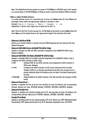
... the GIGABYTE SATA 2 chip. (Default: Enabled) Onboard SATA/IDE Ctrl Mode (GIGABYTE SATA2 Chip) Enables or disables RAID for the SATA controller. (The IDE controller still operates in MS-DOS mode; Advanced Host Controller Interface (AHCI) is an interface specification that allows the storage driver to enable advanced Serial ATA features such as Native Command Queuing and hot plug. Options are not used in a 10/100 Mbps environment, so their Status fields will operate at a speed of the attached LAN cable. Note...
... the GIGABYTE SATA 2 chip. (Default: Enabled) Onboard SATA/IDE Ctrl Mode (GIGABYTE SATA2 Chip) Enables or disables RAID for the SATA controller. (The IDE controller still operates in MS-DOS mode; Advanced Host Controller Interface (AHCI) is an interface specification that allows the storage driver to enable advanced Serial ATA features such as Native Command Queuing and hot plug. Options are not used in a 10/100 Mbps environment, so their Status fields will operate at a speed of the attached LAN cable. Note...
Manual
Page 50
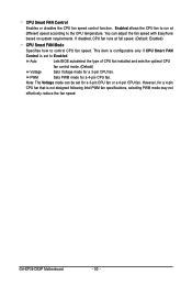
...GA-EP35-DS3P Motherboard - 50 - Auto Lets BIOS autodetect the type of CPU fan installed and sets the optimal CPU fan control mode. (Default) Voltage Sets Voltage mode for a 3-pin CPU fan or a 4-pin CPU fan. This item is configurable only if CPU Smart FAN Control is not designed following Intel PWM fan specifications, selecting PWM mode may not effectively reduce the fan speed. If disabled, CPU fan runs at different speed according to the CPU temperature. PWM Sets PWM mode for a 4-pin CPU fan that is set for a 3-pin CPU fan. Enabled allows the CPU fan to run at full speed...
...GA-EP35-DS3P Motherboard - 50 - Auto Lets BIOS autodetect the type of CPU fan installed and sets the optimal CPU fan control mode. (Default) Voltage Sets Voltage mode for a 3-pin CPU fan or a 4-pin CPU fan. This item is configurable only if CPU Smart FAN Control is not designed following Intel PWM fan specifications, selecting PWM mode may not effectively reduce the fan speed. If disabled, CPU fan runs at different speed according to the CPU temperature. PWM Sets PWM mode for a 4-pin CPU fan that is set for a 3-pin CPU fan. Enabled allows the CPU fan to run at full speed...
Manual
Page 52
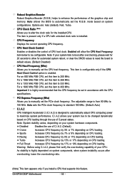
... after overclocking, please wait for 20 seconds to allow the CPU Host Frequency item below to be changed dynamically based on CPU loading through the use of the graphics chip and memory. Options are: Auto (default), Fast, Turbo. Robust Graphics Booster Robust Graphics Booster (R.G.B.) helps to enhance the performance of C.I.A.2. (Default) Cruise Increases CPU frequency by 5% or 7% depending on CPU loading. mode based on system configurations. Important It is highly recommended that supports this...
... after overclocking, please wait for 20 seconds to allow the CPU Host Frequency item below to be changed dynamically based on CPU loading through the use of the graphics chip and memory. Options are: Auto (default), Fast, Turbo. Robust Graphics Booster Robust Graphics Booster (R.G.B.) helps to enhance the performance of C.I.A.2. (Default) Cruise Increases CPU frequency by 5% or 7% depending on CPU loading. mode based on system configurations. Important It is highly recommended that supports this...
Manual
Page 57
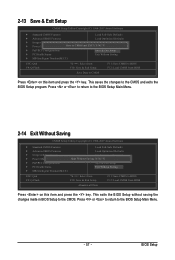
... in BIOS Setup to the BIOS Setup Main Menu. - 57 - Press or to return to the CMOS. BIOS Setup This saves the changes to BIOS F12: Load CMOS from BIOS Abandon all Data Press on this item and press the key. 2-13 Save & Exit Setup CMOS Setup Utility-Copyright (C) 1984-2007 Award Software ` Standard CMOS Features Load Fail-Safe Defaults ` Advanced BIOS Features Load Optimized Defaults ` Integrated Peripherals Set Supervisor Password ` Power Management Setup Save to CMOS and EXIT (SYe/tNU)?seYr Password ` PnP/PCI Configurations...
... in BIOS Setup to the BIOS Setup Main Menu. - 57 - Press or to return to the CMOS. BIOS Setup This saves the changes to BIOS F12: Load CMOS from BIOS Abandon all Data Press on this item and press the key. 2-13 Save & Exit Setup CMOS Setup Utility-Copyright (C) 1984-2007 Award Software ` Standard CMOS Features Load Fail-Safe Defaults ` Advanced BIOS Features Load Optimized Defaults ` Integrated Peripherals Set Supervisor Password ` Power Management Setup Save to CMOS and EXIT (SYe/tNU)?seYr Password ` PnP/PCI Configurations...
Manual
Page 77
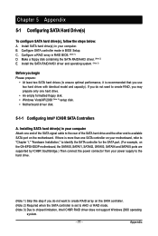
... SATA port on the SATA controller. (Note 2) Required when the SATA controller is recommended that you begin Please prepare: • At least two SATA hard drives (to ensure optimal performance, it is set to AHCI or RAID mode. (Note 3) Due to identify the SATA controller for the SATA port. (For example, on the GA-EP35-DS3P motherboard, the SATAII0, SATAII1, SATAII2, SATAII3, SATAII4 and SATAII5 ports are supported by ICH9R Southbridge.) Then connect the power connector...
... SATA port on the SATA controller. (Note 2) Required when the SATA controller is recommended that you begin Please prepare: • At least two SATA hard drives (to ensure optimal performance, it is set to AHCI or RAID mode. (Note 3) Due to identify the SATA controller for the SATA port. (For example, on the GA-EP35-DS3P motherboard, the SATAII0, SATAII1, SATAII2, SATAII3, SATAII4 and SATAII5 ports are supported by ICH9R Southbridge.) Then connect the power connector...
Manual
Page 83
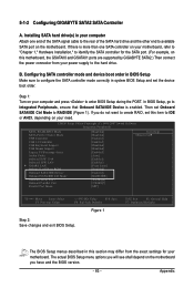
CMOS Setup Utility-Copyright (C) 1984-2007 Award Software Integrated Peripherals SATA RAID/AHCI Mode SATA Port0-3 Native Mode USB Controller USB 2.0 Controller USB Keyboard Support USB Mouse Support Legacy USB storage detect Azalia Codec Onboard H/W 1394 Onboard H/W LAN ` SMART LAN Onboard LAN Boot ROM Onboard SATA/IDE Device Onboard SATA/IDE Ctrl Mode Onboard Serial Port 1 Onboard Parallel Port Parallel Port Mode [Disabled] [Disabled] [Enabled] [Enabled] [Disabled] [Disabled] [Enabled] [Auto] [Enabled] [Enabled] [Press Enter] [Disabled] [Enabled] [RAID/IDE] [3F8/IRQ4] [378/IRQ7] [SPP] ...
CMOS Setup Utility-Copyright (C) 1984-2007 Award Software Integrated Peripherals SATA RAID/AHCI Mode SATA Port0-3 Native Mode USB Controller USB 2.0 Controller USB Keyboard Support USB Mouse Support Legacy USB storage detect Azalia Codec Onboard H/W 1394 Onboard H/W LAN ` SMART LAN Onboard LAN Boot ROM Onboard SATA/IDE Device Onboard SATA/IDE Ctrl Mode Onboard Serial Port 1 Onboard Parallel Port Parallel Port Mode [Disabled] [Disabled] [Enabled] [Enabled] [Disabled] [Disabled] [Enabled] [Auto] [Enabled] [Enabled] [Press Enter] [Disabled] [Enabled] [RAID/IDE] [3F8/IRQ4] [378/IRQ7] [SPP] ...
Manual
Page 84
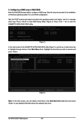
... choices in the Main Menu block. Highlight the item that you can select a hard drive in RAID BIOS Enter the RAID BIOS setup utility to enter RAID Setup Utility" (Figure 2). Skip this step and proceed to the installation of the GIGABYTE SATA2 RAID BIOS utility (Figure 3), use the up or down arrow key to enter RAID Setup Utility ... Figure 2 In the main screen of Windows operating system for a message which says "Press to configure a RAID array. GA-EP35-DS3P Motherboard - 84 - C. After the POST memory test begins...
... choices in the Main Menu block. Highlight the item that you can select a hard drive in RAID BIOS Enter the RAID BIOS setup utility to enter RAID Setup Utility" (Figure 2). Skip this step and proceed to the installation of the GIGABYTE SATA2 RAID BIOS utility (Figure 3), use the up or down arrow key to enter RAID Setup Utility ... Figure 2 In the main screen of Windows operating system for a message which says "Press to configure a RAID array. GA-EP35-DS3P Motherboard - 84 - C. After the POST memory test begins...
Manual
Page 89
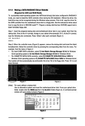
...). Appendix 5-1-3 Making a SATA RAID/AHCI Driver Diskette (Required for AHCI and RAID Mode) To successfully install operating system onto SATA hard drive(s) that is/are configured to RAID/AHCI mode, you need to install the SATA controller driver during the Windows setup process. Figure 1 Figure 2 (Note) For users without a startup disk: Use an alternative system and insert the motherboard driver disk. Press after each command (Figure 1): cd bootdrv menu Step 2: When the controller menu (Figure 2) appears, remove the startup disk and insert...
...). Appendix 5-1-3 Making a SATA RAID/AHCI Driver Diskette (Required for AHCI and RAID Mode) To successfully install operating system onto SATA hard drive(s) that is/are configured to RAID/AHCI mode, you need to install the SATA controller driver during the Windows setup process. Figure 1 Figure 2 (Note) For users without a startup disk: Use an alternative system and insert the motherboard driver disk. Press after each command (Figure 1): cd bootdrv menu Step 2: When the controller menu (Figure 2) appears, remove the startup disk and insert...
Manual
Page 90
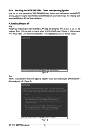
...-ROM drives, or special disk controllers for use with Windows, including those for use with Windows, press ENTER. Windows Setup Press F6 if you see the next screen. S=Specify Additional Device ENTER=Continue F3=Exit Figure 2 GA-EP35-DS3P Motherboard - 90 - Figure 1 Step 2: When a screen similar to that you have prepared the SATA RAID/AHCI driver diskette and configured the required BIOS settings, you are ready to install Windows Vista/XP/2000 onto your system to boot from a mass storage device...
...-ROM drives, or special disk controllers for use with Windows, including those for use with Windows, press ENTER. Windows Setup Press F6 if you see the next screen. S=Specify Additional Device ENTER=Continue F3=Exit Figure 2 GA-EP35-DS3P Motherboard - 90 - Figure 1 Step 2: When a screen similar to that you have prepared the SATA RAID/AHCI driver diskette and configured the required BIOS settings, you are ready to install Windows Vista/XP/2000 onto your system to boot from a mass storage device...
Manual
Page 92
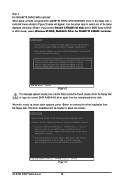
... press . The driver installation will appear. S=Specify Additional Device ENTER=Continue F3=Exit Figure 6 GA-EP35-DS3P Motherboard - 92 - Use the arrow keys to select one or some file(s) cannot be finished in the floppy disk, a controller menu similar to the previous screen. (Windows XP/2003) RAID/AHCI Driver for GIGABYTE GBB36X Controller (Windows 2000) RAID Driver for GIGABYTE GBB363 Controller (Windows 2000) AHCI Driver for GIGABYTE GBB363 Controller (Windows 2000) RAID Driver for which you have any device support disks from a mass storage device manufacturer, or do...
... press . The driver installation will appear. S=Specify Additional Device ENTER=Continue F3=Exit Figure 6 GA-EP35-DS3P Motherboard - 92 - Use the arrow keys to select one or some file(s) cannot be finished in the floppy disk, a controller menu similar to the previous screen. (Windows XP/2003) RAID/AHCI Driver for GIGABYTE GBB36X Controller (Windows 2000) RAID Driver for GIGABYTE GBB363 Controller (Windows 2000) AHCI Driver for GIGABYTE GBB363 Controller (Windows 2000) RAID Driver for which you have any device support disks from a mass storage device manufacturer, or do...


