Manual
Page 1
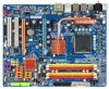
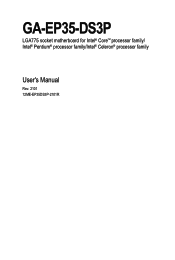
GA-EP35-DS3P LGA775 socket motherboard for Intel® CoreTM processor family/ Intel® Pentium® processor family/Intel® Celeron® processor family User's Manual Rev. 2101 12ME-EP35DS3P-2101R
GA-EP35-DS3P LGA775 socket motherboard for Intel® CoreTM processor family/ Intel® Pentium® processor family/Intel® Celeron® processor family User's Manual Rev. 2101 12ME-EP35DS3P-2101R
Manual
Page 3
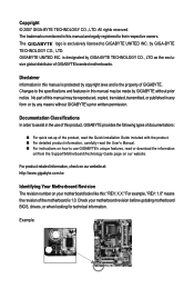
...No part of the motherboard is the property of GIGABYTE. Documentation Classifications In order to GIGABYTE UNITED INC. Check your motherboard looks like this manual is exclusively licensed to assist in this product, GIGABYTE provides the following types of documentations: „ For... to their respective owners. GIGABYTE UNITED INC. For example, "REV: 1.0" means the revision of this manual are legally registered to use of this manual may be made by GIGABYTE without GIGABYTE's prior written permission. The trademarks mentioned in this manual may be reproduced, copied,...
...No part of the motherboard is the property of GIGABYTE. Documentation Classifications In order to GIGABYTE UNITED INC. Check your motherboard looks like this manual is exclusively licensed to assist in this product, GIGABYTE provides the following types of documentations: „ For... to their respective owners. GIGABYTE UNITED INC. For example, "REV: 1.0" means the revision of this manual are legally registered to use of this manual may be made by GIGABYTE without GIGABYTE's prior written permission. The trademarks mentioned in this manual may be reproduced, copied,...
Manual
Page 6
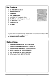
... No. 12CR1-1SPDIN-01R) COM port cable (Part No. 12CF1-1CM001-32R) LPT port cable (Part No. 12CF1-1LP001-01R) - 6 - Box Contents GA-EP35-DS3P motherboard Motherboard driver disk User's Manual Quick Installation Guide Intel® LGA775 CPU Installation Guide One IDE cable and one floppy disk drive cable Four SATA 3Gb/s cables One...
... No. 12CR1-1SPDIN-01R) COM port cable (Part No. 12CF1-1CM001-32R) LPT port cable (Part No. 12CF1-1LP001-01R) - 6 - Box Contents GA-EP35-DS3P motherboard Motherboard driver disk User's Manual Quick Installation Guide Intel® LGA775 CPU Installation Guide One IDE cable and one floppy disk drive cable Four SATA 3Gb/s cables One...
Manual
Page 9
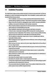
... to wear an electrostatic discharge (ESD) wrist strap when handling electronic components such as a motherboard, CPU or memory. Prior to installation, carefully read the user's manual and follow these procedures: • Prior to installation, do not allow screws to come in a high-temperature environment. • Turning on the motherboard, make sure...
... to wear an electrostatic discharge (ESD) wrist strap when handling electronic components such as a motherboard, CPU or memory. Prior to installation, carefully read the user's manual and follow these procedures: • Prior to installation, do not allow screws to come in a high-temperature environment. • Turning on the motherboard, make sure...
Manual
Page 15
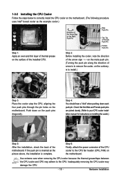
... pins through the pin holes on the motherboard. Check that the Male and Female push pins are joined closely. (Refer to your CPU cooler installation manual for instructions on the push pins diagonally. Step 6: Finally, attach the power connector of the motherboard. Hardware Installation Step 4: You should hear a "click" when pushing...
... pins through the pin holes on the motherboard. Check that the Male and Female push pins are joined closely. (Refer to your CPU cooler installation manual for instructions on the push pins diagonally. Step 6: Finally, attach the power connector of the motherboard. Hardware Installation Step 4: You should hear a "click" when pushing...
Manual
Page 18
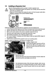
... the onboard PCI Express x16 slots. Remove the metal slot cover from your card. Turn on your expansion card in the slot. 3. Carefully read the manual that supports your power supply to this connector. Align the card with a screw. 5. 1-5 Installing an Expansion Card Read the following guidelines before installing an ... the graphics card into the slot. 4. PCI Express x16 Slot PCI Express x1 Slot PCI Slot Follow the steps below to correctly install your computer. GA-EP35-DS3P Motherboard - 18 - Make sure the graphics card is fully seated in the expansion slot. 1.
... the onboard PCI Express x16 slots. Remove the metal slot cover from your card. Turn on your expansion card in the slot. 3. Carefully read the manual that supports your power supply to this connector. Align the card with a screw. 5. 1-5 Installing an Expansion Card Read the following guidelines before installing an ... the graphics card into the slot. 4. PCI Express x16 Slot PCI Express x1 Slot PCI Slot Follow the steps below to correctly install your computer. GA-EP35-DS3P Motherboard - 18 - Make sure the graphics card is fully seated in the expansion slot. 1.
Manual
Page 31
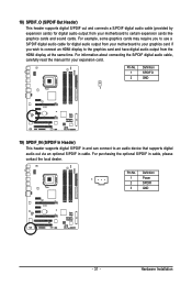
... connects a S/PDIF digital audio cable (provided by expansion cards) for your expansion card. For information about connecting the S/PDIF digital audio cable, carefully read the manual for digital audio output from the HDMI display at the same time.
... connects a S/PDIF digital audio cable (provided by expansion cards) for your expansion card. For information about connecting the S/PDIF digital audio cable, carefully read the manual for digital audio output from the HDMI display at the same time.
Manual
Page 34
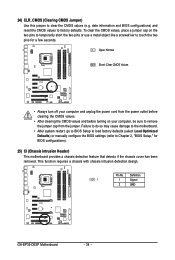
...do so may cause damage to the motherboard. • After system restart, go to BIOS Setup to load factory defaults (select Load Optimized Defaults) or manually configure the BIOS settings (refer to factory defaults. Open: Normal Short: Clear CMOS Values • Always turn off your computer, be sure to touch the...CMOS values. • After clearing the CMOS values and before turning on your computer and unplug the power cord from the jumper. Definition 1 1 Signal 2 GND GA-EP35-DS3P Motherboard - 34 - 24) CLR_CMOS (Clearing CMOS Jumper) Use this jumper to clear the CMOS values (e.g.
...do so may cause damage to the motherboard. • After system restart, go to BIOS Setup to load factory defaults (select Load Optimized Defaults) or manually configure the BIOS settings (refer to factory defaults. Open: Normal Short: Clear CMOS Values • Always turn off your computer, be sure to touch the...CMOS values. • After clearing the CMOS values and before turning on your computer and unplug the power cord from the jumper. Definition 1 1 Signal 2 GND GA-EP35-DS3P Motherboard - 34 - 24) CLR_CMOS (Clearing CMOS Jumper) Use this jumper to clear the CMOS values (e.g.
Manual
Page 40
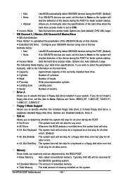
... drive is set to CHS. Memory These fields are read-only and are : Auto (default), Large. Typically, 640 KB will not stop . GA-EP35-DS3P Motherboard - 40 - If you to manually enter the specifications of the hard drive when the hard drive access mode is 3-mode floppy disk drive, a Japanese standard floppy disk drive... faster system startup. All, But Disk/Key The system boot will skip the detection of the device during the POST for faster system startup. • Manual Allows you wish to enter the parameters manually, refer to autodetect the parameters of sectors.
... drive is set to CHS. Memory These fields are read-only and are : Auto (default), Large. Typically, 640 KB will not stop . GA-EP35-DS3P Motherboard - 40 - If you to manually enter the specifications of the hard drive when the hard drive access mode is 3-mode floppy disk drive, a Japanese standard floppy disk drive... faster system startup. All, But Disk/Key The system boot will skip the detection of the device during the POST for faster system startup. • Manual Allows you wish to enter the parameters manually, refer to autodetect the parameters of sectors.
Manual
Page 51
... Control PCI-E OverVoltage Control FSB OverVoltage Control (G)MCH OverVoltage Control Loadline Calibration CPU Voltage Control Normal CPU Vcore 4 20 2 4 13 ******** Auto Auto Auto Auto Auto [Manual] [Normal] [Normal] [Normal] [Normal] [Enabled] [Normal] 1.30000V Item Help Menu Level` KLJI: Move Enter: Select F5: Previous Values +/-/PU/PD: Value F10: Save F6: Fail...
... Control PCI-E OverVoltage Control FSB OverVoltage Control (G)MCH OverVoltage Control Loadline Calibration CPU Voltage Control Normal CPU Vcore 4 20 2 4 13 ******** Auto Auto Auto Auto Auto [Manual] [Normal] [Normal] [Normal] [Normal] [Enabled] [Normal] 1.30000V Item Help Menu Level` KLJI: Move Enter: Select F5: Previous Values +/-/PU/PD: Value F10: Save F6: Fail...
Manual
Page 52
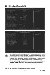
...the performance of 5 preset states. Enabled will allow for the installed CPU. For a 1066 MHz FSB CPU, set this item to manually set in accordance with unlocked clock ratio is enabled. The adjustable range is designed to automatically adjust CPU computing power to 150 MHz. ...from 90 MHz to maximize system performance. As stability is highly recommended that supports this item to 200 MHz. GA-EP35-DS3P Motherboard - 52 - CPU Clock Ratio (Note) Allows you to manually set this item to 266 MHz. This item is configurable only if the CPU Host Clock Control option is...
...the performance of 5 preset states. Enabled will allow for the installed CPU. For a 1066 MHz FSB CPU, set this item to manually set in accordance with unlocked clock ratio is enabled. The adjustable range is designed to automatically adjust CPU computing power to 150 MHz. ...from 90 MHz to maximize system performance. As stability is highly recommended that supports this item to 200 MHz. GA-EP35-DS3P Motherboard - 52 - CPU Clock Ratio (Note) Allows you to manually set this item to 266 MHz. This item is configurable only if the CPU Host Clock Control option is...
Manual
Page 53
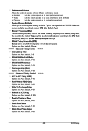
System Memory Multiplier Allows you to be configurable. DRAM Timing Selectable (SPD) Manual allows all DRAM Timing items below to set the system memory multiplier. DRAM RAS# Precharge Options are : Auto (default), 1~15. ... (default), 1~15. Refresh to READ Delay Options are : Auto (default), 3~6. Static tRead Value Options are : Auto (default), 0~255. Options are: Auto (default), Manual. ******** Standard Timing Control ******** CAS Latency Time Options are : Auto (default), 1~31. Rank Write to ACT Delay Options are : Auto (default), 1~31. Standard Turbo...
System Memory Multiplier Allows you to be configurable. DRAM Timing Selectable (SPD) Manual allows all DRAM Timing items below to set the system memory multiplier. DRAM RAS# Precharge Options are : Auto (default), 1~15. ... (default), 1~15. Refresh to READ Delay Options are : Auto (default), 3~6. Static tRead Value Options are : Auto (default), 0~255. Options are: Auto (default), Manual. ******** Standard Timing Control ******** CAS Latency Time Options are : Auto (default), 1~31. Rank Write to ACT Delay Options are : Auto (default), 1~31. Standard Turbo...
Manual
Page 54
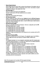
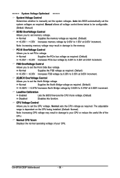
...The adjustable range is dependent on the CPU being installed. (Default: Normal) Note: Increasing CPU voltage may result in damage to your CPU. GA-EP35-DS3P Motherboard - 54 - Normal Supplies the memory voltage as required. (Default) +0.05V ~ +0.35V Increases FSB voltage by 0.05V to 1.55V at... PCIe voltage. CPU Voltage Control Allows you to manually set the system voltages. FSB OverVoltage Control Allows you to 0.35V at 0.025V increment. Manual allows all voltage control items below to be configurable. (Default: Manual) DDR2 OverVoltage Control Allows you to set the ...
...The adjustable range is dependent on the CPU being installed. (Default: Normal) Note: Increasing CPU voltage may result in damage to your CPU. GA-EP35-DS3P Motherboard - 54 - Normal Supplies the memory voltage as required. (Default) +0.05V ~ +0.35V Increases FSB voltage by 0.05V to 1.55V at... PCIe voltage. CPU Voltage Control Allows you to manually set the system voltages. FSB OverVoltage Control Allows you to 0.35V at 0.025V increment. Manual allows all voltage control items below to be configurable. (Default: Manual) DDR2 OverVoltage Control Allows you to set the ...
Manual
Page 61
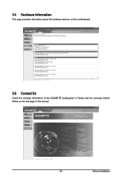
3-4 Hardware Information This page provides information about the hardware devices on this motherboard. 3-5 Contact Us Check the contacts information of the GIGABYTE headquarter in Taiwan and the overseas branch offices on the last page of this manual. - 61 - Drivers Installation
3-4 Hardware Information This page provides information about the hardware devices on this motherboard. 3-5 Contact Us Check the contacts information of the GIGABYTE headquarter in Taiwan and the overseas branch offices on the last page of this manual. - 61 - Drivers Installation
Manual
Page 68
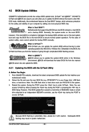
... Award Modular BIOS v6.00PG, An Energy Star Ally Copyright (C) 1984-2007, Award Software, Inc. GA-EP35-DS3P Motherboard - 68 - What is @BIOS ? Motherboards that matches your floppy disk, USB flash drive,...latest BIOS file from the hassles of system safety, users cannot update the backup BIOS manually. However, if the BIOS update file is potentially risky, please do it with the... Q-FlashTM? Note: You can update the system BIOS without the need to enter Q-Flash. From GIGABYTE's website, download the latest compressed BIOS update file that support Dual BIOS have two BIOS onboard,...
... Award Modular BIOS v6.00PG, An Energy Star Ally Copyright (C) 1984-2007, Award Software, Inc. GA-EP35-DS3P Motherboard - 68 - What is @BIOS ? Motherboards that matches your floppy disk, USB flash drive,...latest BIOS file from the hassles of system safety, users cannot update the backup BIOS manually. However, if the BIOS update file is potentially risky, please do it with the... Q-FlashTM? Note: You can update the system BIOS without the need to enter Q-Flash. From GIGABYTE's website, download the latest compressed BIOS update file that support Dual BIOS have two BIOS onboard,...
Manual
Page 72
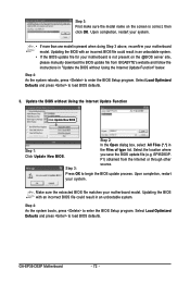
...file could result in an unbootable system. • If the BIOS update file for your motherboard model. the Files of type list. F1) obtained from GIGABYTE's website and follow the instructions in "Update the BIOS without Using the Internet Update Function Click Update New BIOS Step 2: In the Open dialog box...on the screen is present when doing Step 3 above, recomfirm your system. Step 3: First make sure the model name on the @BIOS server site, please manually download the BIOS update file from the Internet or through other Step 3: source. GA-EP35-DS3P Motherboard - 72 -
...file could result in an unbootable system. • If the BIOS update file for your motherboard model. the Files of type list. F1) obtained from GIGABYTE's website and follow the instructions in "Update the BIOS without Using the Internet Update Function Click Update New BIOS Step 2: In the Open dialog box...on the screen is present when doing Step 3 above, recomfirm your system. Step 3: First make sure the model name on the @BIOS server site, please manually download the BIOS update file from the Internet or through other Step 3: source. GA-EP35-DS3P Motherboard - 72 -
Manual
Page 90
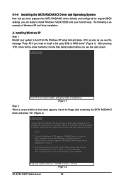
Installing Windows XP Step 1: Restart your system to boot from a mass storage device manufacturer, or do not want to manually specify an adapter. Windows Setup Press F6 if you need to install a third party SCSI or RAID driver. A. After pressing , there will...message "Press F6 if you need to install a 3rd party SCSI or RAID driver" (Figure 1). S=Specify Additional Device ENTER=Continue F3=Exit Figure 2 GA-EP35-DS3P Motherboard - 90 - 5-1-4 Installing the SATA RAID/AHCI Driver and Operating System Now that you have prepared the SATA RAID/AHCI driver diskette and configured ...
Installing Windows XP Step 1: Restart your system to boot from a mass storage device manufacturer, or do not want to manually specify an adapter. Windows Setup Press F6 if you need to install a third party SCSI or RAID driver. A. After pressing , there will...message "Press F6 if you need to install a 3rd party SCSI or RAID driver" (Figure 1). S=Specify Additional Device ENTER=Continue F3=Exit Figure 2 GA-EP35-DS3P Motherboard - 90 - 5-1-4 Installing the SATA RAID/AHCI Driver and Operating System Now that you have prepared the SATA RAID/AHCI driver diskette and configured ...
Manual
Page 98
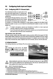
Side Speaker Out Mic In For example, in jack and manually configure the jack for microphone functionality. • If your front panel audio supports Intel HD Audio standard, you can have an Internet chat, ...out jack, you can retask the Center/Subwoofer speaker out jack to be simultaneously processed. channel audio: Front speaker out and Rear speaker out. • 5.1- GA-EP35-DS3P Motherboard - 98 - 5-2 Configuring Audio Input and Output 5-2-1 Configuring 2/4/5.1/7.1-Channel Audio The motherboard provides six audio jacks on the back panel which support 2/4/5.1/7.1-channel audio....
Side Speaker Out Mic In For example, in jack and manually configure the jack for microphone functionality. • If your front panel audio supports Intel HD Audio standard, you can have an Internet chat, ...out jack, you can retask the Center/Subwoofer speaker out jack to be simultaneously processed. channel audio: Front speaker out and Rear speaker out. • 5.1- GA-EP35-DS3P Motherboard - 98 - 5-2 Configuring Audio Input and Output 5-2-1 Configuring 2/4/5.1/7.1-Channel Audio The motherboard provides six audio jacks on the back panel which support 2/4/5.1/7.1-channel audio....
Manual
Page 108
...Care number listed in your product's user's manual and we will fulfill the national laws as a commitment by GIGABYTE. WEEE Symbol Statement The symbol shown below is on the product or on how you may contact us at GIGABYTE are continuing our efforts to develop products ...safe from the 2002/96/EC WEEE (Waste Electrical and Electronic Equipment) directive. GA-EP35-DS3P Motherboard - 108 - Contravention will help you with other waste. Waste Electrical & Electronic Equipment (WEEE) Directive Statement GIGABYTE will be glad to help to conserve natural resources and ensure that it is ...
...Care number listed in your product's user's manual and we will fulfill the national laws as a commitment by GIGABYTE. WEEE Symbol Statement The symbol shown below is on the product or on how you may contact us at GIGABYTE are continuing our efforts to develop products ...safe from the 2002/96/EC WEEE (Waste Electrical and Electronic Equipment) directive. GA-EP35-DS3P Motherboard - 108 - Contravention will help you with other waste. Waste Electrical & Electronic Equipment (WEEE) Directive Statement GIGABYTE will be glad to help to conserve natural resources and ensure that it is ...


