Manual
Page 1
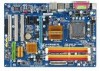
GA-EP31-DS3L LGA775 socket motherboard for Intel® CoreTM processor family/ Intel® Pentium® processor family/Intel® Celeron® processor family User's Manual Rev. 2102 12ME-EP31DS3L-2102R
GA-EP31-DS3L LGA775 socket motherboard for Intel® CoreTM processor family/ Intel® Pentium® processor family/Intel® Celeron® processor family User's Manual Rev. 2102 12ME-EP31DS3L-2102R

Manual
Page 2
Motherboard GA-EP31-DS3L Aug. 4, 2008 Motherboard GA-EP31-DS3L Aug. 4, 2008
Motherboard GA-EP31-DS3L Aug. 4, 2008 Motherboard GA-EP31-DS3L Aug. 4, 2008
Manual
Page 3
... Example: For product-related information, check on our website at: http://www.gigabyte.com.tw Identifying Your Motherboard Revision The revision number on your motherboard revision before updating motherboard BIOS, drivers, or when looking for technical information. Disclaimer Information in this...GIGA-BYTE TECHNOLOGY CO., LTD. Documentation Classifications In order to their respective owners. Check your motherboard looks like this manual may be made by GIGABYTE without GIGABYTE's prior written permission. All rights reserved. The trademarks mentioned in this manual may be ...
... Example: For product-related information, check on our website at: http://www.gigabyte.com.tw Identifying Your Motherboard Revision The revision number on your motherboard revision before updating motherboard BIOS, drivers, or when looking for technical information. Disclaimer Information in this...GIGA-BYTE TECHNOLOGY CO., LTD. Documentation Classifications In order to their respective owners. Check your motherboard looks like this manual may be made by GIGABYTE without GIGABYTE's prior written permission. All rights reserved. The trademarks mentioned in this manual may be ...
Manual
Page 4
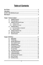
Table of Contents Box Contents ...6 OptionalItems...6 GA-EP31-DS3L Motherboard Layout 7 Block Diagram...8 Chapter 1 Hardware Installation 9 1-1 Installation Precautions 9 1-2 Product Specifications 10 1-3 Installing the CPU and CPU Cooler 13 1-3-1 Installing the CPU 13 1-3-2 Installing the CPU ...
Table of Contents Box Contents ...6 OptionalItems...6 GA-EP31-DS3L Motherboard Layout 7 Block Diagram...8 Chapter 1 Hardware Installation 9 1-1 Installation Precautions 9 1-2 Product Specifications 10 1-3 Installing the CPU and CPU Cooler 13 1-3-1 Installing the CPU 13 1-3-2 Installing the CPU ...
Manual
Page 6
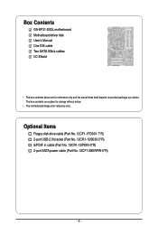
Box Contents GA-EP31-DS3L motherboard Motherboard driver disk User's Manual One IDE cable Two SATA 3Gb/s cables I/O Shield • The box contents above are subject to change without notice. • The motherboard image is for reference only and the actual items shall depend on product package you obtain. The box contents are for reference only. Optional Items Floppy disk drive cable (Part No. 12CF1-1FD001-7*R) 2-port USB 2.0 bracket (Part No. 12CR1-1UB030-5*R) S/PDIF in cable (Part No. 12CR1-1SPDIN-0*R) 2-port SATA power cable (Part No. 12CF1-2SERPW-0*R) - 6 -
Box Contents GA-EP31-DS3L motherboard Motherboard driver disk User's Manual One IDE cable Two SATA 3Gb/s cables I/O Shield • The box contents above are subject to change without notice. • The motherboard image is for reference only and the actual items shall depend on product package you obtain. The box contents are for reference only. Optional Items Floppy disk drive cable (Part No. 12CF1-1FD001-7*R) 2-port USB 2.0 bracket (Part No. 12CR1-1UB030-5*R) S/PDIF in cable (Part No. 12CR1-1SPDIN-0*R) 2-port SATA power cable (Part No. 12CF1-2SERPW-0*R) - 6 -
Manual
Page 7
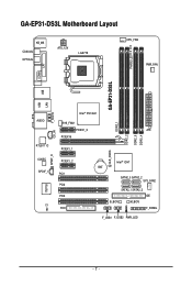
GA-EP31-DS3L Motherboard Layout KB_MS COAXIAL OPTICAL ATX_12V LGA775 CPU_FAN PWR_FAN PHASE LED COMA LPT GA-EP31-DS3L USB USB LAN AUDIO RTL8111C CODEC SPDIF_I CI IT8718 SPDIF_O CD_IN F_AUDIO Intel® P31/G31 DDR2_1 SYS_FAN1 PCIEX1_3 ATX PCIEX16 DDR2_2 DDR2_3 DDR2_4 PCIEX1_1 CLR_CMOS PCIEX1_2 PCI1 PCI2 PCI3 FDD Intel® ICH7 BAT SATA2_0 SATA2_2 SYS_FAN2 SATA2_1 SATA2_3 IDE B_BIOS M_BIOS F_PANEL F_USB1 F_USB2 PWR_LED - 7 -
GA-EP31-DS3L Motherboard Layout KB_MS COAXIAL OPTICAL ATX_12V LGA775 CPU_FAN PWR_FAN PHASE LED COMA LPT GA-EP31-DS3L USB USB LAN AUDIO RTL8111C CODEC SPDIF_I CI IT8718 SPDIF_O CD_IN F_AUDIO Intel® P31/G31 DDR2_1 SYS_FAN1 PCIEX1_3 ATX PCIEX16 DDR2_2 DDR2_3 DDR2_4 PCIEX1_1 CLR_CMOS PCIEX1_2 PCI1 PCI2 PCI3 FDD Intel® ICH7 BAT SATA2_0 SATA2_2 SYS_FAN2 SATA2_1 SATA2_3 IDE B_BIOS M_BIOS F_PANEL F_USB1 F_USB2 PWR_LED - 7 -
Manual
Page 9
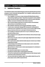
...; To prevent damage to the use of electrostatic discharge (ESD). These stickers are connected tightly and securely. • When handling the motherboard, avoid touching any installation steps or have it on top of an antistatic pad or within the computer casing. • Do not... dry and first touch a metal object to eliminate static electricity. • Prior to installing the motherboard, please have a problem related to the motherboard, do not remove or break motherboard S/N (Serial Number) sticker or warranty sticker provided by unplugging the power cord from the power outlet...
...; To prevent damage to the use of electrostatic discharge (ESD). These stickers are connected tightly and securely. • When handling the motherboard, avoid touching any installation steps or have it on top of an antistatic pad or within the computer casing. • Do not... dry and first touch a metal object to eliminate static electricity. • Prior to installing the motherboard, please have a problem related to the motherboard, do not remove or break motherboard S/N (Serial Number) sticker or warranty sticker provided by unplugging the power cord from the power outlet...

Manual
Page 10
...Extreme Edition/Intel® Pentium® 4 processor/ Intel® Celeron® processor in the LGA 775 package (Go to GIGABYTE's website for the latest CPU support list.) Š L2 cache varies with CPU Š 1333/1066/800 MHz FSB ... (Note 1) Š Dual channel memory architecture Š Support for DDR2 1066/800/667 MHz memory modules (Go to GIGABYTE's website for the latest memory support list.) Š Realtek ALC888 codec Š High Definition Audio Š 2/4/5.1/7.1-channel ...the back panel, 4 via the USB brackets connected to the internal USB headers) GA-EP31-DS3L Motherboard - 10 -
...Extreme Edition/Intel® Pentium® 4 processor/ Intel® Celeron® processor in the LGA 775 package (Go to GIGABYTE's website for the latest CPU support list.) Š L2 cache varies with CPU Š 1333/1066/800 MHz FSB ... (Note 1) Š Dual channel memory architecture Š Support for DDR2 1066/800/667 MHz memory modules (Go to GIGABYTE's website for the latest memory support list.) Š Realtek ALC888 codec Š High Definition Audio Š 2/4/5.1/7.1-channel ...the back panel, 4 via the USB brackets connected to the internal USB headers) GA-EP31-DS3L Motherboard - 10 -

Manual
Page 12
GA-EP31-DS3L Motherboard - 12 - For example, 4 GB of memory size will instead be shown as 3.xx GB during system startup. (Note 2) Whether the CPU/system fan speed control ... Š ATX Form Factor; 30.5cm x 21.0cm (Note 1) Based on the CPU/ system cooler you install. (Note 3) Available functions in EasyTune may differ by motherboard model. (Note 4) Due to the hardware limitation, you must install the Intel® CoreTM 2 Extreme/ CoreTM 2 Quad/ CoreTM 2 Duo/ Pentium Dual-Core/ Celeron Dual-Core...
GA-EP31-DS3L Motherboard - 12 - For example, 4 GB of memory size will instead be shown as 3.xx GB during system startup. (Note 2) Whether the CPU/system fan speed control ... Š ATX Form Factor; 30.5cm x 21.0cm (Note 1) Based on the CPU/ system cooler you install. (Note 3) Available functions in EasyTune may differ by motherboard model. (Note 4) Due to the hardware limitation, you must install the Intel® CoreTM 2 Extreme/ CoreTM 2 Quad/ CoreTM 2 Duo/ Pentium Dual-Core/ Celeron Dual-Core...

Manual
Page 13
...standard requirements for the latest CPU support list.) • Always turn on the surface of the CPU. Locate the alignment keys on the motherboard CPU socket and the notches on the CPU - 13 - 1-3 Installing the CPU and CPU Cooler Read the following guidelines before installing the...CPU host frequency in accordance with the CPU specifications. If you wish to set beyond the standard specifications, please do so according to GIGABYTE's website for the peripherals. Hardware Installation It is not installed, otherwise overheating and damage of the CPU Socket Notch Notch Triangle Pin...
...standard requirements for the latest CPU support list.) • Always turn on the surface of the CPU. Locate the alignment keys on the motherboard CPU socket and the notches on the CPU - 13 - 1-3 Installing the CPU and CPU Cooler Read the following guidelines before installing the...CPU host frequency in accordance with the CPU specifications. If you wish to set beyond the standard specifications, please do so according to GIGABYTE's website for the peripherals. Hardware Installation It is not installed, otherwise overheating and damage of the CPU Socket Notch Notch Triangle Pin...

Manual
Page 14
..., always replace the protective socket cover when the CPU is properly inserted, replace the load plate and push the CPU socket lever back into the motherboard CPU socket. Align the CPU pin one marking (triangle) with the pin one corner of the CPU socket (or you may align the CPU notches... the CPU. Step 5: Once the CPU is not installed.) Step 4: Hold the CPU with the socket alignment keys) and gently insert the CPU into position. GA-EP31-DS3L Motherboard - 14 -
..., always replace the protective socket cover when the CPU is properly inserted, replace the load plate and push the CPU socket lever back into the motherboard CPU socket. Align the CPU pin one marking (triangle) with the pin one corner of the CPU socket (or you may align the CPU notches... the CPU. Step 5: Once the CPU is not installed.) Step 4: Hold the CPU with the socket alignment keys) and gently insert the CPU into position. GA-EP31-DS3L Motherboard - 14 -

Manual
Page 15
... may damage the CPU. - 15 - 1-3-2 Installing the CPU Cooler Follow the steps below to correctly install the CPU cooler on the motherboard. (The following procedure uses Intel® boxed cooler as the picture above, the installation is to your CPU cooler installation manual for instructions...joined closely. (Refer to install.) Step 3: Place the cooler atop the CPU, aligning the four push pins through the pin holes on the motherboard. Hardware Installation Step 6: Finally, attach the power connector of arrow is to remove the cooler, on the contrary, is complete. Inadequately removing...
... may damage the CPU. - 15 - 1-3-2 Installing the CPU Cooler Follow the steps below to correctly install the CPU cooler on the motherboard. (The following procedure uses Intel® boxed cooler as the picture above, the installation is to your CPU cooler installation manual for instructions...joined closely. (Refer to install.) Step 3: Place the cooler atop the CPU, aligning the four push pins through the pin holes on the motherboard. Hardware Installation Step 6: Finally, attach the power connector of arrow is to remove the cooler, on the contrary, is complete. Inadequately removing...
Manual
Page 16
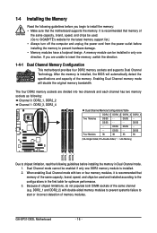
A memory module can be used . (Go to GIGABYTE's website for optimum performance. 3. Enabling Dual Channel memory..., brand, speed, and chips be installed in only one DDR2 memory module is recommended that memory of memory modules. GA-EP31-DS3L Motherboard - 16 - DS/SS - - DS/SS DS/SS - - - - When enabling Dual Channel mode with ...before installing the memory to insert the memory, switch the direction. 1-4-1 Dual Channel Memory Configuration This motherboard provides four DDR2 memory sockets and supports Dual Channel Technology. The four DDR2 memory sockets are unable to...
A memory module can be used . (Go to GIGABYTE's website for optimum performance. 3. Enabling Dual Channel memory..., brand, speed, and chips be installed in only one DDR2 memory module is recommended that memory of memory modules. GA-EP31-DS3L Motherboard - 16 - DS/SS - - DS/SS DS/SS - - - - When enabling Dual Channel mode with ...before installing the memory to insert the memory, switch the direction. 1-4-1 Dual Channel Memory Configuration This motherboard provides four DDR2 memory sockets and supports Dual Channel Technology. The four DDR2 memory sockets are unable to...

Manual
Page 17
... , make sure to turn off the computer and unplug the power cord from the power outlet to prevent damage to install DDR2 DIMMs on this motherboard. Follow the steps below to correctly install your fingers on the socket.
... , make sure to turn off the computer and unplug the power cord from the power outlet to prevent damage to install DDR2 DIMMs on this motherboard. Follow the steps below to correctly install your fingers on the socket.
Manual
Page 18
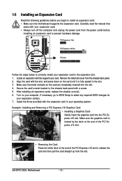
... 6. Example: Installing and Removing a PCI Express x16 Graphics Card: • Installing a Graphics Card: Gently insert the graphics card into the slot. 4. GA-EP31-DS3L Motherboard - 18 - Locate an expansion slot that came with the slot, and press down on the card until it is locked by the latch at the...Card: Press the white latch at the end of the PCI Express x16 slot to install an expansion card: • Make sure the motherboard supports the expansion card. Make sure the metal contacts on your operating system. Align the card with your expansion card. • Always turn...
... 6. Example: Installing and Removing a PCI Express x16 Graphics Card: • Installing a Graphics Card: Gently insert the graphics card into the slot. 4. GA-EP31-DS3L Motherboard - 18 - Locate an expansion slot that came with the slot, and press down on the card until it is locked by the latch at the...Card: Press the white latch at the end of the PCI Express x16 slot to install an expansion card: • Make sure the motherboard supports the expansion card. Make sure the metal contacts on your operating system. Align the card with your expansion card. • Always turn...

Manual
Page 19
...) to 1 Gbps data rate. The parallel port is occurring • When removing the cable connected to a back panel connector, first remove the cable from the motherboard. • When removing the cable, pull it side to side to an external audio system that your device and then remove it from your audio...
...) to 1 Gbps data rate. The parallel port is occurring • When removing the cable connected to a back panel connector, first remove the cable from the motherboard. • When removing the cable, pull it side to side to an external audio system that your device and then remove it from your audio...

Manual
Page 20
... Out Jack (Gray) Use this audio jack for a headphone or 2-channel speaker. Use this audio jack to connect center/subwoofer speakers in a 5.1/7.1-channel audio configuration. GA-EP31-DS3L Motherboard - 20 -
... Out Jack (Gray) Use this audio jack for a headphone or 2-channel speaker. Use this audio jack to connect center/subwoofer speakers in a 5.1/7.1-channel audio configuration. GA-EP31-DS3L Motherboard - 20 -

Manual
Page 21
..., make sure your devices are compliant with the connectors you wish to connect. • Before installing the devices, be sure to the connector on the motherboard. - 21 -
..., make sure your devices are compliant with the connectors you wish to connect. • Before installing the devices, be sure to the connector on the motherboard. - 21 -

Manual
Page 22
... 3.3V -12V GND PS_ON(soft On/Off) GND GND GND -5V +5V +5V +5V (Only for 2x12-pinATX) GND (Only for 2x12-pin ATX) GA-EP31-DS3L Motherboard - 22 - The 12V power connector mainly supplies power to the power connector in the correct orientation. Do not insert the power supply cable into pins... under the protective cover when using a 2x12 power supply, remove the protective cover from the main power connector on the motherboard. If a power supply is used that can lead to an unstable or unbootable system. • The main power connector is turned off and all...
... 3.3V -12V GND PS_ON(soft On/Off) GND GND GND -5V +5V +5V +5V (Only for 2x12-pinATX) GND (Only for 2x12-pin ATX) GA-EP31-DS3L Motherboard - 22 - The 12V power connector mainly supplies power to the power connector in the correct orientation. Do not insert the power supply cable into pins... under the protective cover when using a 2x12 power supply, remove the protective cover from the main power connector on the motherboard. If a power supply is used that can lead to an unstable or unbootable system. • The main power connector is turned off and all...

Manual
Page 23
...Speed Control SYS_FAN1 / PWR_FAN : Pin No. The types of the cable is used to connect a floppy disk drive. Hardware Installation The motherboard supports CPU fan speed control, which requires the use of the connector and the floppy disk drive cable. For optimum heat dissipation, it ... fan with fan speed control design. Most fan headers possess a foolproof insertion design. 3/4/5/6) CPU_FAN/SYS_FAN1/SYS_FAN2/PWR_FAN (Fan Headers) The motherboard has a 4-pin CPU fan header (CPU_FAN), a 4-pin system fan header (SYS_FAN2), a 3-pin system fan header (SYS_FAN1), and a 3-pin ...
...Speed Control SYS_FAN1 / PWR_FAN : Pin No. The types of the cable is used to connect a floppy disk drive. Hardware Installation The motherboard supports CPU fan speed control, which requires the use of the connector and the floppy disk drive cable. For optimum heat dissipation, it ... fan with fan speed control design. Most fan headers possess a foolproof insertion design. 3/4/5/6) CPU_FAN/SYS_FAN1/SYS_FAN2/PWR_FAN (Fan Headers) The motherboard has a 4-pin CPU fan header (CPU_FAN), a 4-pin system fan header (SYS_FAN2), a 3-pin system fan header (SYS_FAN1), and a 3-pin ...


