Manual
Page 1
GA-EP31-DS3L LGA775 socket motherboard for Intel® CoreTM processor family/ Intel® Pentium® processor family/Intel® Celeron® processor family User's Manual Rev. 2102 12ME-EP31DS3L-2102R
GA-EP31-DS3L LGA775 socket motherboard for Intel® CoreTM processor family/ Intel® Pentium® processor family/Intel® Celeron® processor family User's Manual Rev. 2102 12ME-EP31DS3L-2102R

Manual
Page 2
Motherboard GA-EP31-DS3L Aug. 4, 2008 Motherboard GA-EP31-DS3L Aug. 4, 2008
Motherboard GA-EP31-DS3L Aug. 4, 2008 Motherboard GA-EP31-DS3L Aug. 4, 2008
Manual
Page 3
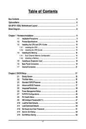
... For instructions on how to assist in the use of GIGABYTE. For product-related information, check on our website at: http://www.gigabyte.com.tw Identifying Your Motherboard Revision The revision number on our website. The trademarks mentioned in any... means without prior notice. Documentation Classifications In order to use GIGABYTE's unique features, read or download the information on/from the Support&Downloads\Motherboard\Technology Guide page on your motherboard revision before updating motherboard BIOS, drivers, or when looking for technical information. For ...
... For instructions on how to assist in the use of GIGABYTE. For product-related information, check on our website at: http://www.gigabyte.com.tw Identifying Your Motherboard Revision The revision number on our website. The trademarks mentioned in any... means without prior notice. Documentation Classifications In order to use GIGABYTE's unique features, read or download the information on/from the Support&Downloads\Motherboard\Technology Guide page on your motherboard revision before updating motherboard BIOS, drivers, or when looking for technical information. For ...
Manual
Page 4
Table of Contents Box Contents ...6 OptionalItems...6 GA-EP31-DS3L Motherboard Layout 7 Block Diagram...8 Chapter 1 Hardware Installation 9 1-1 Installation Precautions 9 1-2 Product Specifications 10 1-3 Installing the CPU and CPU Cooler 13 1-3-1 Installing the CPU 13 1-3-2 Installing the CPU ...
Table of Contents Box Contents ...6 OptionalItems...6 GA-EP31-DS3L Motherboard Layout 7 Block Diagram...8 Chapter 1 Hardware Installation 9 1-1 Installation Precautions 9 1-2 Product Specifications 10 1-3 Installing the CPU and CPU Cooler 13 1-3-1 Installing the CPU 13 1-3-2 Installing the CPU ...
Manual
Page 6
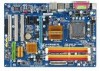
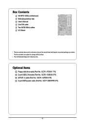
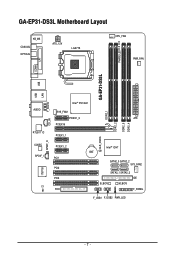
Optional Items Floppy disk drive cable (Part No. 12CF1-1FD001-7*R) 2-port USB 2.0 bracket (Part No. 12CR1-1UB030-5*R) S/PDIF in cable (Part No. 12CR1-1SPDIN-0*R) 2-port SATA power cable (Part No. 12CF1-2SERPW-0*R) - 6 - Box Contents GA-EP31-DS3L motherboard Motherboard driver disk User's Manual One IDE cable Two SATA 3Gb/s cables I/O Shield • The box contents above are subject to change without notice. • The motherboard image is for reference only and the actual items shall depend on product package you obtain. The box contents are for reference only.
Optional Items Floppy disk drive cable (Part No. 12CF1-1FD001-7*R) 2-port USB 2.0 bracket (Part No. 12CR1-1UB030-5*R) S/PDIF in cable (Part No. 12CR1-1SPDIN-0*R) 2-port SATA power cable (Part No. 12CF1-2SERPW-0*R) - 6 - Box Contents GA-EP31-DS3L motherboard Motherboard driver disk User's Manual One IDE cable Two SATA 3Gb/s cables I/O Shield • The box contents above are subject to change without notice. • The motherboard image is for reference only and the actual items shall depend on product package you obtain. The box contents are for reference only.
Manual
Page 7
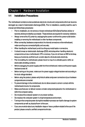
GA-EP31-DS3L Motherboard Layout KB_MS COAXIAL OPTICAL ATX_12V LGA775 CPU_FAN PWR_FAN PHASE LED COMA LPT GA-EP31-DS3L USB USB LAN AUDIO RTL8111C CODEC SPDIF_I CI IT8718 SPDIF_O CD_IN F_AUDIO Intel® P31/G31 DDR2_1 SYS_FAN1 PCIEX1_3 ATX PCIEX16 DDR2_2 DDR2_3 DDR2_4 PCIEX1_1 CLR_CMOS PCIEX1_2 PCI1 PCI2 PCI3 FDD Intel® ICH7 BAT SATA2_0 SATA2_2 SYS_FAN2 SATA2_1 SATA2_3 IDE B_BIOS M_BIOS F_PANEL F_USB1 F_USB2 PWR_LED - 7 -
GA-EP31-DS3L Motherboard Layout KB_MS COAXIAL OPTICAL ATX_12V LGA775 CPU_FAN PWR_FAN PHASE LED COMA LPT GA-EP31-DS3L USB USB LAN AUDIO RTL8111C CODEC SPDIF_I CI IT8718 SPDIF_O CD_IN F_AUDIO Intel® P31/G31 DDR2_1 SYS_FAN1 PCIEX1_3 ATX PCIEX16 DDR2_2 DDR2_3 DDR2_4 PCIEX1_1 CLR_CMOS PCIEX1_2 PCI1 PCI2 PCI3 FDD Intel® ICH7 BAT SATA2_0 SATA2_2 SYS_FAN2 SATA2_1 SATA2_3 IDE B_BIOS M_BIOS F_PANEL F_USB1 F_USB2 PWR_LED - 7 -
Manual
Page 9
... has been turned off. • Before turning on the power, make sure they are connected tightly and securely. • When handling the motherboard, avoid touching any metal leads or connectors. • It is best to wear an electrostatic discharge (ESD) wrist strap when handling electronic components...are required for warranty validation. • Always remove the AC power by your hardware components are connected. • To prevent damage to the motherboard, do not have an ESD wrist strap, keep your hands dry and first touch a metal object to eliminate static electricity. • Prior to...
... has been turned off. • Before turning on the power, make sure they are connected tightly and securely. • When handling the motherboard, avoid touching any metal leads or connectors. • It is best to wear an electrostatic discharge (ESD) wrist strap when handling electronic components...are required for warranty validation. • Always remove the AC power by your hardware components are connected. • To prevent damage to the motherboard, do not have an ESD wrist strap, keep your hands dry and first touch a metal object to eliminate static electricity. • Prior to...

Manual
Page 10
...Extreme Edition/Intel® Pentium® 4 processor/ Intel® Celeron® processor in the LGA 775 package (Go to GIGABYTE's website for the latest CPU support list.) Š L2 cache varies with CPU Š 1333/1066/800 MHz FSB ... (Note 1) Š Dual channel memory architecture Š Support for DDR2 1066/800/667 MHz memory modules (Go to GIGABYTE's website for the latest memory support list.) Š Realtek ALC888 codec Š High Definition Audio Š 2/4/5.1/7.1-channel ...the back panel, 4 via the USB brackets connected to the internal USB headers) GA-EP31-DS3L Motherboard - 10 -
...Extreme Edition/Intel® Pentium® 4 processor/ Intel® Celeron® processor in the LGA 775 package (Go to GIGABYTE's website for the latest CPU support list.) Š L2 cache varies with CPU Š 1333/1066/800 MHz FSB ... (Note 1) Š Dual channel memory architecture Š Support for DDR2 1066/800/667 MHz memory modules (Go to GIGABYTE's website for the latest memory support list.) Š Realtek ALC888 codec Š High Definition Audio Š 2/4/5.1/7.1-channel ...the back panel, 4 via the USB brackets connected to the internal USB headers) GA-EP31-DS3L Motherboard - 10 -

Manual
Page 12
...system fan speed control function is supported will depend on standard PC architecture, a certain amount of memory is less than the stated amount. GA-EP31-DS3L Motherboard - 12 - Unique Features Bundled Software Operating System Form Factor Š Support for @BIOS Š Support for Download Center Š ...Factor; 30.5cm x 21.0cm (Note 1) Based on the CPU/ system cooler you install. (Note 3) Available functions in EasyTune may differ by motherboard model. (Note 4) Due to the hardware limitation, you must install the Intel® CoreTM 2 Extreme/ CoreTM 2 Quad/ CoreTM 2 Duo/ Pentium ...
...system fan speed control function is supported will depend on standard PC architecture, a certain amount of memory is less than the stated amount. GA-EP31-DS3L Motherboard - 12 - Unique Features Bundled Software Operating System Form Factor Š Support for @BIOS Š Support for Download Center Š ...Factor; 30.5cm x 21.0cm (Note 1) Based on the CPU/ system cooler you install. (Note 3) Available functions in EasyTune may differ by motherboard model. (Note 4) Due to the hardware limitation, you must install the Intel® CoreTM 2 Extreme/ CoreTM 2 Quad/ CoreTM 2 Duo/ Pentium ...

Manual
Page 13
... Notch Triangle Pin One Marking on the CPU. It is not installed, otherwise overheating and damage of the CPU. Locate the alignment keys on the motherboard CPU socket and the notches on the CPU - 13 - The CPU cannot be set the frequency beyond hardware specifications since it does not meet the.... • Locate the pin one of the CPU may occur. • Set the CPU host frequency in accordance with the CPU specifications. mended that the motherboard supports the CPU. (Go to GIGABYTE's website for the peripherals.
... Notch Triangle Pin One Marking on the CPU. It is not installed, otherwise overheating and damage of the CPU. Locate the alignment keys on the motherboard CPU socket and the notches on the CPU - 13 - The CPU cannot be set the frequency beyond hardware specifications since it does not meet the.... • Locate the pin one of the CPU may occur. • Set the CPU host frequency in accordance with the CPU specifications. mended that the motherboard supports the CPU. (Go to GIGABYTE's website for the peripherals.

Manual
Page 14
... Hold the CPU with the socket alignment keys) and gently insert the CPU into position. CPU Socket Lever Step 1: Completely raise the CPU socket lever. GA-EP31-DS3L Motherboard - 14 - Follow the steps below to turn off the computer and unplug the power cord from the load plate. (To protect the CPU socket, always... replace the protective socket cover when the CPU is properly inserted, replace the load plate and push the CPU socket lever back into the motherboard CPU socket. Before installing the CPU, make sure to correctly install the CPU into its locked position. B.
... Hold the CPU with the socket alignment keys) and gently insert the CPU into position. CPU Socket Lever Step 1: Completely raise the CPU socket lever. GA-EP31-DS3L Motherboard - 14 - Follow the steps below to turn off the computer and unplug the power cord from the load plate. (To protect the CPU socket, always... replace the protective socket cover when the CPU is properly inserted, replace the load plate and push the CPU socket lever back into the motherboard CPU socket. Before installing the CPU, make sure to correctly install the CPU into its locked position. B.

Manual
Page 15
...of the CPU cooler to your CPU cooler installation manual for instructions on installing the cooler.) Step 5: After the installation, check the back of the motherboard. 1-3-2 Installing the CPU Cooler Follow the steps below to install.) Step 3: Place the cooler atop the CPU, aligning the four push pins through... the pin holes on the motherboard. Inadequately removing the CPU cooler may adhere to the CPU. Hardware Installation Direction of the Arrow Sign on the Male Push Pin Male Push ...
...of the CPU cooler to your CPU cooler installation manual for instructions on installing the cooler.) Step 5: After the installation, check the back of the motherboard. 1-3-2 Installing the CPU Cooler Follow the steps below to install.) Step 3: Place the cooler atop the CPU, aligning the four push pins through... the pin holes on the motherboard. Inadequately removing the CPU cooler may adhere to the CPU. Hardware Installation Direction of the Arrow Sign on the Male Push Pin Male Push ...
Manual
Page 16
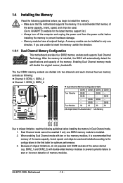
... the power cord from the power outlet before installing the memory in only one DDR2 memory module is recommended that the motherboard supports the memory. DS/SS Four Modules SS SS SS SS (SS=Single-Sided, DS=Double-Sided, "- -"=No...GIGABYTE's website for optimum performance. 3. Dual Channel mode cannot be installed in Dual Channel mode. 1. The four DDR2 memory sockets are unable to insert the memory, switch the direction. 1-4-1 Dual Channel Memory Configuration This motherboard provides four DDR2 memory sockets and supports Dual Channel Technology. GA-EP31-DS3L Motherboard...
... the power cord from the power outlet before installing the memory in only one DDR2 memory module is recommended that the motherboard supports the memory. DS/SS Four Modules SS SS SS SS (SS=Single-Sided, DS=Double-Sided, "- -"=No...GIGABYTE's website for optimum performance. 3. Dual Channel mode cannot be installed in Dual Channel mode. 1. The four DDR2 memory sockets are unable to insert the memory, switch the direction. 1-4-1 Dual Channel Memory Configuration This motherboard provides four DDR2 memory sockets and supports Dual Channel Technology. GA-EP31-DS3L Motherboard...

Manual
Page 17
... fingers on the top edge of the memory socket. Step 2: The clips at both ends of the memory module. Place the memory module on this motherboard. DDR2 DIMMs are not compatible to DDR DIMMs. Be sure to the memory module. Hardware Installation As indicated in the picture on the memory and...
... fingers on the top edge of the memory socket. Step 2: The clips at both ends of the memory module. Place the memory module on this motherboard. DDR2 DIMMs are not compatible to DDR DIMMs. Be sure to the memory module. Hardware Installation As indicated in the picture on the memory and...
Manual
Page 18
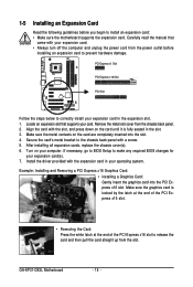
...computer and unplug the power cord from the power outlet before you begin to install an expansion card: • Make sure the motherboard supports the expansion card. Install the driver provided with your computer. PCI Express x1 Slot PCI Express x16 Slot PCI Slot Follow ... Express x16 slot. • Removing the Card: Press the white latch at the end of the PCI Express x16 slot to correctly install your card. GA-EP31-DS3L Motherboard - 18 - Example: Installing and Removing a PCI Express x16 Graphics Card: • Installing a Graphics Card: Gently insert the graphics card into the ...
...computer and unplug the power cord from the power outlet before you begin to install an expansion card: • Make sure the motherboard supports the expansion card. Install the driver provided with your computer. PCI Express x1 Slot PCI Express x16 Slot PCI Slot Follow ... Express x16 slot. • Removing the Card: Press the white latch at the end of the PCI Express x16 slot to correctly install your card. GA-EP31-DS3L Motherboard - 18 - Example: Installing and Removing a PCI Express x16 Graphics Card: • Installing a Graphics Card: Gently insert the graphics card into the ...

Manual
Page 19
... LAN port LEDs. Coaxial S/PDIF Out Connector This connector provides digital audio out to 1 Gbps data rate. Do not rock it straight out from the motherboard. • When removing the cable, pull it side to side to connect a PS/2 keyboard. Use this feature, ensure that supports digital coaxial audio. The parallel...
... LAN port LEDs. Coaxial S/PDIF Out Connector This connector provides digital audio out to 1 Gbps data rate. Do not rock it straight out from the motherboard. • When removing the cable, pull it side to side to connect a PS/2 keyboard. Use this feature, ensure that supports digital coaxial audio. The parallel...

Manual
Page 20
... drive, walkman, etc. Mic In Jack (Pink) The default Mic in jack ( ). Microphones must be used to connect front speakers in Chapter 5, "Configuring 2/4/5.1/7.1-Channel Audio." GA-EP31-DS3L Motherboard - 20 - Rear Speaker Out Jack (Black) Use this jack. Only microphones still MUST be reconfigured to perform different functions via the audio software. Refer to...
... drive, walkman, etc. Mic In Jack (Pink) The default Mic in jack ( ). Microphones must be used to connect front speakers in Chapter 5, "Configuring 2/4/5.1/7.1-Channel Audio." GA-EP31-DS3L Motherboard - 20 - Rear Speaker Out Jack (Black) Use this jack. Only microphones still MUST be reconfigured to perform different functions via the audio software. Refer to...

Manual
Page 21
...) CD_IN 14) SPDIF_I 15) SPDIF_O 16) F_USB1/F_USB2 17) CI 18) CLR_CMOS 19) BAT 20) PHASE LED Read the following guidelines before turning on the motherboard. - 21 - Hardware Installation Unplug the power cord from the power outlet to prevent damage to the devices. • After installing the device and before connecting...
...) CD_IN 14) SPDIF_I 15) SPDIF_O 16) F_USB1/F_USB2 17) CI 18) CLR_CMOS 19) BAT 20) PHASE LED Read the following guidelines before turning on the motherboard. - 21 - Hardware Installation Unplug the power cord from the power outlet to prevent damage to the devices. • After installing the device and before connecting...

Manual
Page 22
...3V -12V GND PS_ON(soft On/Off) GND GND GND -5V +5V +5V +5V (Only for 2x12-pinATX) GND (Only for 2x12-pin ATX) GA-EP31-DS3L Motherboard - 22 - Do not insert the power supply cable into pins under the protective cover when using a 2x12 power supply, remove the protective cover from the... main power connector on the motherboard. The 12V power connector mainly supplies power to the power connector in the correct orientation. If a power supply is used (500W or greater)....
...3V -12V GND PS_ON(soft On/Off) GND GND GND -5V +5V +5V +5V (Only for 2x12-pinATX) GND (Only for 2x12-pin ATX) GA-EP31-DS3L Motherboard - 22 - Do not insert the power supply cable into pins under the protective cover when using a 2x12 power supply, remove the protective cover from the... main power connector on the motherboard. The 12V power connector mainly supplies power to the power connector in the correct orientation. If a power supply is used (500W or greater)....

Manual
Page 23
For optimum heat dissipation, it in damage to locate pin 1 of a CPU fan with fan speed control design. The motherboard supports CPU fan speed control, which requires the use of the connector and the floppy disk drive cable. Definition 1 GND 2 +12V 3 ... Sense 4 +5V • Be sure to connect fan cables to the fan headers to connect a floppy disk drive. 3/4/5/6) CPU_FAN/SYS_FAN1/SYS_FAN2/PWR_FAN (Fan Headers) The motherboard has a 4-pin CPU fan header (CPU_FAN), a 4-pin system fan header (SYS_FAN2), a 3-pin system fan header (SYS_FAN1), and a 3-pin power fan header (PWR_FAN...
For optimum heat dissipation, it in damage to locate pin 1 of a CPU fan with fan speed control design. The motherboard supports CPU fan speed control, which requires the use of the connector and the floppy disk drive cable. Definition 1 GND 2 +12V 3 ... Sense 4 +5V • Be sure to connect fan cables to the fan headers to connect a floppy disk drive. 3/4/5/6) CPU_FAN/SYS_FAN1/SYS_FAN2/PWR_FAN (Fan Headers) The motherboard has a 4-pin CPU fan header (CPU_FAN), a 4-pin system fan header (SYS_FAN2), a 3-pin system fan header (SYS_FAN1), and a 3-pin power fan header (PWR_FAN...


