Manual
Page 1
GA-EG41M-S2H/ GA-EG41M-S2 LGA775 socket motherboard for Intel® CoreTM processor family/ Intel® Pentium® processor family/Intel® Celeron® processor family User's Manual Rev. 1003 12ME-EG41MS2H-1003R
GA-EG41M-S2H/ GA-EG41M-S2 LGA775 socket motherboard for Intel® CoreTM processor family/ Intel® Pentium® processor family/Intel® Celeron® processor family User's Manual Rev. 1003 12ME-EG41MS2H-1003R

Manual
Page 2
Motherboard GA-EG41M-S2H/GA-EG41M-S2 Oct. 20, 2008 Motherboard GA-EG41M-S2H/ GA-EG41M-S2 Oct. 20, 2008
Motherboard GA-EG41M-S2H/GA-EG41M-S2 Oct. 20, 2008 Motherboard GA-EG41M-S2H/ GA-EG41M-S2 Oct. 20, 2008
Manual
Page 3
...carefully read or download the information on/from the Support\Motherboard\Technology Guide page on your motherboard revision before updating motherboard BIOS, drivers, or when looking for technical information. The trademarks mentioned in the use GIGABYTE's unique features, read the User's Manual. ... For instructions on how to use of this manual are legally registered to assist in this product, GIGABYTE provides the following types of the motherboard is the property of this manual may be reproduced, copied, translated, transmitted, or published in this : "REV...
...carefully read or download the information on/from the Support\Motherboard\Technology Guide page on your motherboard revision before updating motherboard BIOS, drivers, or when looking for technical information. The trademarks mentioned in the use GIGABYTE's unique features, read the User's Manual. ... For instructions on how to use of this manual are legally registered to assist in this product, GIGABYTE provides the following types of the motherboard is the property of this manual may be reproduced, copied, translated, transmitted, or published in this : "REV...

Manual
Page 4
Table of Contents Box Contents ...6 OptionalItems ...6 GA-EG41M-S2H/S2 Motherboard Layout 7 Block Diagram ...8 Chapter 1 Hardware Installation 9 1-1 Installation Precautions 9 1-2 Product Specifications 10 1-3 Installing the CPU and CPU Cooler 13 1-3-1 Installing the CPU 13 1-3-2 Installing the CPU ...
Table of Contents Box Contents ...6 OptionalItems ...6 GA-EG41M-S2H/S2 Motherboard Layout 7 Block Diagram ...8 Chapter 1 Hardware Installation 9 1-1 Installation Precautions 9 1-2 Product Specifications 10 1-3 Installing the CPU and CPU Cooler 13 1-3-1 Installing the CPU 13 1-3-2 Installing the CPU ...
Manual
Page 6
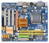
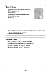
Box Contents GA-EG41M-S2H or GA-EG41M-S2 motherboard Motherboard driver disk User's Manual One IDE cable and one floppy disk drive cable Two SATA 3Gb/s cables I/O Shield • The box contents above are subject to change without notice. • The motherboard image is for reference only and the actual items shall depend on product package you obtain...
Box Contents GA-EG41M-S2H or GA-EG41M-S2 motherboard Motherboard driver disk User's Manual One IDE cable and one floppy disk drive cable Two SATA 3Gb/s cables I/O Shield • The box contents above are subject to change without notice. • The motherboard image is for reference only and the actual items shall depend on product package you obtain...
Manual
Page 7
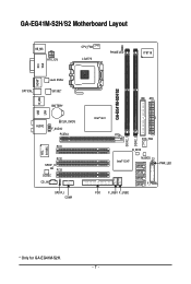
GA-EG41M-S2H/S2 Motherboard Layout KB_MS ATX_12V CPU_FAN LGA775 PHASE LED IT8718 VGA DVI OPTICAL HDMI* Level Shifter SiI1392* BATTERY USB R_USB LAN AUDIO CLR_CMOS F_AUDIO PCIEX4 PCI1 RTL 8110SC PCI2 SPDIF_O PCI3 CODEC CD_IN SPDIF_I COMA GA-EG41M-S2H/S2 Intel® G41 IDE ATX DDR2_1 DDR2_2 SYS_FAN B_BIOS Intel® ICH7 M_BIOS CI SATA2_3 PWR_LED SATA2_2 SATA2_1 SATA2_0 F_PANEL FDD F_USB1 F_USB2 * Only for GA-EG41M-S2H. - 7 -
GA-EG41M-S2H/S2 Motherboard Layout KB_MS ATX_12V CPU_FAN LGA775 PHASE LED IT8718 VGA DVI OPTICAL HDMI* Level Shifter SiI1392* BATTERY USB R_USB LAN AUDIO CLR_CMOS F_AUDIO PCIEX4 PCI1 RTL 8110SC PCI2 SPDIF_O PCI3 CODEC CD_IN SPDIF_I COMA GA-EG41M-S2H/S2 Intel® G41 IDE ATX DDR2_1 DDR2_2 SYS_FAN B_BIOS Intel® ICH7 M_BIOS CI SATA2_3 PWR_LED SATA2_2 SATA2_1 SATA2_0 F_PANEL FDD F_USB1 F_USB2 * Only for GA-EG41M-S2H. - 7 -
Manual
Page 9
...: • Prior to installation, do not allow screws to come in a high-temperature environment. • Turning on the motherboard, make sure the power supply voltage has been set according to the local voltage standard. • Before using the product, please... result of the product, please consult a certified computer technician. - 9 - Hardware Installation Chapter 1 Hardware Installation 1-1 Installation Precautions The motherboard contains numerous delicate electronic circuits and components which can lead to damage to system components as well as physical harm to the user. &#...
...: • Prior to installation, do not allow screws to come in a high-temperature environment. • Turning on the motherboard, make sure the power supply voltage has been set according to the local voltage standard. • Before using the product, please... result of the product, please consult a certified computer technician. - 9 - Hardware Installation Chapter 1 Hardware Installation 1-1 Installation Precautions The motherboard contains numerous delicate electronic circuits and components which can lead to damage to system components as well as physical harm to the user. &#...
Manual
Page 10
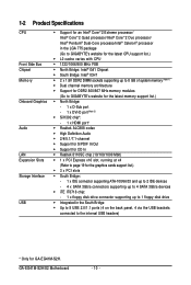
GA-EG41M-S2H/S2 Motherboard - 10 - 1-2 Product Specifications CPU Front Side Bus Chipset Memory Onboard ...Intel® Pentium® Dual-Core processo/Intel® Celeron® processor in the LGA 775 package (Go to GIGABYTE's website for the latest CPU support list.) L2 cache varies with CPU 1333/1066/800 MHz...up to 8 GB of system memory (Note 1) Dual channel memory architecture Support for DDR2 800/667 MHz memory modules (Go to GIGABYTE's website for the latest memory support list.) North Bridge: - 1 x D-Sub port - 1 x DVI-D port (Note 2) ...
GA-EG41M-S2H/S2 Motherboard - 10 - 1-2 Product Specifications CPU Front Side Bus Chipset Memory Onboard ...Intel® Pentium® Dual-Core processo/Intel® Celeron® processor in the LGA 775 package (Go to GIGABYTE's website for the latest CPU support list.) L2 cache varies with CPU 1333/1066/800 MHz...up to 8 GB of system memory (Note 1) Dual channel memory architecture Support for DDR2 800/667 MHz memory modules (Go to GIGABYTE's website for the latest memory support list.) North Bridge: - 1 x D-Sub port - 1 x DVI-D port (Note 2) ...
Manual
Page 12
... CPU/System fan speed control function is supported will depend on the CPU/ System cooler you install. (Note 4) Available functions in EasyTune may differ by motherboard model. GA-EG41M-S2H/S2 Motherboard - 12 -
... CPU/System fan speed control function is supported will depend on the CPU/ System cooler you install. (Note 4) Available functions in EasyTune may differ by motherboard model. GA-EG41M-S2H/S2 Motherboard - 12 -
Manual
Page 13
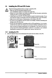
...; Set the CPU host frequency in accordance with the CPU specifications. Locate the alignment keys on the motherboard CPU socket and the notches on the CPU - 13 - mended that the motherboard supports the CPU. (Go to GIGABYTE's website for the peripherals. LGA775 CPU Socket Alignment Key LGA 775 CPU Alignment Key Pin One...
...; Set the CPU host frequency in accordance with the CPU specifications. Locate the alignment keys on the motherboard CPU socket and the notches on the CPU - 13 - mended that the motherboard supports the CPU. (Go to GIGABYTE's website for the peripherals. LGA775 CPU Socket Alignment Key LGA 775 CPU Alignment Key Pin One...
Manual
Page 14
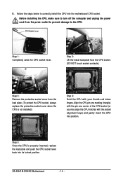
.... (DO NOT touch socket contacts.) Step 3: Remove the protective socket cover from the power outlet to prevent damage to correctly install the CPU into the motherboard CPU socket. CPU Socket Lever Step 1: Completely raise the CPU socket lever. B. Align the CPU pin one marking (triangle) with the pin one corner of....) Step 4: Hold the CPU with the socket alignment keys) and gently insert the CPU into its locked position. Follow the steps below to the CPU. GA-EG41M-S2H/S2 Motherboard - 14 -
.... (DO NOT touch socket contacts.) Step 3: Remove the protective socket cover from the power outlet to prevent damage to correctly install the CPU into the motherboard CPU socket. CPU Socket Lever Step 1: Completely raise the CPU socket lever. B. Align the CPU pin one marking (triangle) with the pin one corner of....) Step 4: Hold the CPU with the socket alignment keys) and gently insert the CPU into its locked position. Follow the steps below to the CPU. GA-EG41M-S2H/S2 Motherboard - 14 -
Manual
Page 15
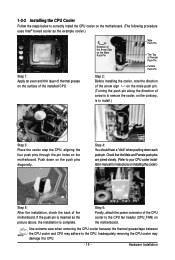
...joined closely. (Refer to the CPU fan header (CPU_FAN) on installing the cooler.) Step 5: After the installation, check the back of the motherboard. Step 6: Finally, attach the power connector of the CPU cooler to your CPU cooler installation manual for instructions on the...on the push pins diagonally. Step 4: You should hear a "click" when pushing down on the motherboard. Inadequately removing the CPU cooler may adhere to correctly install the CPU cooler on the motherboard. (The following procedure uses Intel® boxed cooler as the picture above, the installation is to remove...
...joined closely. (Refer to the CPU fan header (CPU_FAN) on installing the cooler.) Step 5: After the installation, check the back of the motherboard. Step 6: Finally, attach the power connector of the CPU cooler to your CPU cooler installation manual for instructions on the...on the push pins diagonally. Step 4: You should hear a "click" when pushing down on the motherboard. Inadequately removing the CPU cooler may adhere to correctly install the CPU cooler on the motherboard. (The following procedure uses Intel® boxed cooler as the picture above, the installation is to remove...
Manual
Page 16
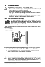
... install the memory: • Make sure that memory of the same capacity, brand, speed, and chips be used . (Go to GIGABYTE's website for the latest memory support list.) • Always turn off the computer and unplug the power cord from the power outlet before... mode cannot be installed in Dual Channel mode. 1. 1-4 Installing the Memory Read the following guidelines before installing the memory in only one direction. GA-EG41M-S2H/S2 Motherboard - 16 - When memory modules of the memory. A memory module can be enabled if only one memory socket as following: Channel 0: DDR2_1...
... install the memory: • Make sure that memory of the same capacity, brand, speed, and chips be used . (Go to GIGABYTE's website for the latest memory support list.) • Always turn off the computer and unplug the power cord from the power outlet before... mode cannot be installed in Dual Channel mode. 1. 1-4 Installing the Memory Read the following guidelines before installing the memory in only one direction. GA-EG41M-S2H/S2 Motherboard - 16 - When memory modules of the memory. A memory module can be enabled if only one memory socket as following: Channel 0: DDR2_1...

Manual
Page 17
Follow the steps below to install DDR2 DIMMs on this motherboard. Place the memory module on the top edge of the socket will snap into the memory socket. Step 1: Note the orientation of the memory socket. ...
Follow the steps below to install DDR2 DIMMs on this motherboard. Place the memory module on the top edge of the socket will snap into the memory socket. Step 1: Note the orientation of the memory socket. ...
Manual
Page 18
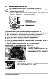
... the expansion card. If necessary, go to BIOS Setup to make any required BIOS changes for your computer. GA-EG41M-S2H/S2 Motherboard - 18 - 1-5 Installing an Expansion Card Read the following guidelines before installing an expansion card to prevent hardware damage. Make sure the metal contacts on your ...
... the expansion card. If necessary, go to BIOS Setup to make any required BIOS changes for your computer. GA-EG41M-S2H/S2 Motherboard - 18 - 1-5 Installing an Expansion Card Read the following guidelines before installing an expansion card to prevent hardware damage. Make sure the metal contacts on your ...
Manual
Page 20
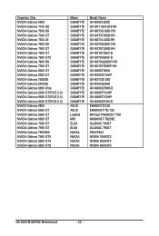
...7600 GT NVIDIA Geforce 7900 GT NVIDIA Geforce 7950GX2 NVIDIA Geforce 7900 GTX NVIDIA Geforce 8800 GTX NVIDIA Geforce 8600 GTS Maker GIGABYTE GIGABYTE GIGABYTE GIGABYTE GIGABYTE GIGABYTE GIGABYTE GIGABYTE GIGABYTE GIGABYTE GIGABYTE GIGABYTE GIGABYTE GIGABYTE GIGABYTE GIGABYTE GIGABYTE GIGABYTE GIGABYTE ASUS ASUS Leadtek MSI ELSA ELSA NVIDIA NVIDIA NVIDIA NVIDIA Model Name GV-NX65128DE GV-NX71G512P8-RH GV-NX73G128D-RH GV-NX73T256D.../TD/128 WinFast PX6600GT TDH NX6800GT-TD256E GLADIAC 760GT GLADIAC 790GT P502/P602 NVIDIA 7900GTX NVIDIA 8800GTX NVIDIA 8600GTS GA-EG41M-S2H/S2 Motherboard - 20 -
...7600 GT NVIDIA Geforce 7900 GT NVIDIA Geforce 7950GX2 NVIDIA Geforce 7900 GTX NVIDIA Geforce 8800 GTX NVIDIA Geforce 8600 GTS Maker GIGABYTE GIGABYTE GIGABYTE GIGABYTE GIGABYTE GIGABYTE GIGABYTE GIGABYTE GIGABYTE GIGABYTE GIGABYTE GIGABYTE GIGABYTE GIGABYTE GIGABYTE GIGABYTE GIGABYTE GIGABYTE GIGABYTE ASUS ASUS Leadtek MSI ELSA ELSA NVIDIA NVIDIA NVIDIA NVIDIA Model Name GV-NX65128DE GV-NX71G512P8-RH GV-NX73G128D-RH GV-NX73T256D.../TD/128 WinFast PX6600GT TDH NX6800GT-TD256E GLADIAC 760GT GLADIAC 790GT P502/P602 NVIDIA 7900GTX NVIDIA 8800GTX NVIDIA 8600GTS GA-EG41M-S2H/S2 Motherboard - 20 -
Manual
Page 22
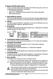
...(s) Optical S/PDIF Out Connector This connector provides digital audio out to an external audio system that your device and then remove it from the motherboard. • When removing the cable, pull it side to side to 1 Gbps data rate. Side Speaker Out Jack (Gray) Use this...default speakers settings, the ~ audio jacks can be connected to connect side speakers in jack. Do not rock it straight out from the connector. GA-EG41M-S2H/S2 Motherboard - 22 - B. Use this port for a headphone or 2-channel speaker. Only microphones still MUST be used to this feature, ensure that ...
...(s) Optical S/PDIF Out Connector This connector provides digital audio out to an external audio system that your device and then remove it from the motherboard. • When removing the cable, pull it side to side to 1 Gbps data rate. Side Speaker Out Jack (Gray) Use this...default speakers settings, the ~ audio jacks can be connected to connect side speakers in jack. Do not rock it straight out from the connector. GA-EG41M-S2H/S2 Motherboard - 22 - B. Use this port for a headphone or 2-channel speaker. Only microphones still MUST be used to this feature, ensure that ...
Manual
Page 23
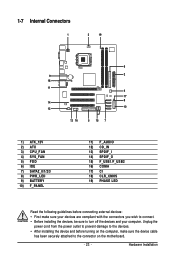
... devices and your devices are compliant with the connectors you wish to connect. • Before installing the devices, be sure to the connector on the motherboard. - 23 - Hardware Installation 1-7 Internal Connectors 1 3 19 9 18 11 14 12 1) ATX_12V 2) ATX 3) CPU_FAN 4) SYS_FAN 5) FDD 6) IDE 7) SATA2_0/1/2/3 8) PWR_LED 9) BATTERY 10) F_PANEL 6 2 4 17 8 10 13 16...
... devices and your devices are compliant with the connectors you wish to connect. • Before installing the devices, be sure to the connector on the motherboard. - 23 - Hardware Installation 1-7 Internal Connectors 1 3 19 9 18 11 14 12 1) ATX_12V 2) ATX 3) CPU_FAN 4) SYS_FAN 5) FDD 6) IDE 7) SATA2_0/1/2/3 8) PWR_LED 9) BATTERY 10) F_PANEL 6 2 4 17 8 10 13 16...
Manual
Page 24
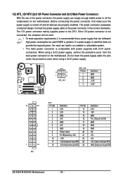
... GND PS_ON(soft On/Off) GND GND GND -5V +5V +5V +5V (Only for 2x12-pin ATX) GND (Only for 2x12-pin ATX) GA-EG41M-S2H/S2 Motherboard - 24 - Do not insert the power supply cable into pins under the protective cover when using a 2x12 power supply, remove the protective cover from the... main power connector on the motherboard. 1/2) ATX_12V/ATX (2x2 12V Power Connector and 2x12 Main Power Connector) With the use of the power connector, the power supply can supply enough...
... GND PS_ON(soft On/Off) GND GND GND -5V +5V +5V +5V (Only for 2x12-pin ATX) GND (Only for 2x12-pin ATX) GA-EG41M-S2H/S2 Motherboard - 24 - Do not insert the power supply cable into pins under the protective cover when using a 2x12 power supply, remove the protective cover from the... main power connector on the motherboard. 1/2) ATX_12V/ATX (2x2 12V Power Connector and 2x12 Main Power Connector) With the use of the power connector, the power supply can supply enough...
Manual
Page 25
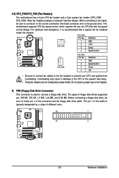
The motherboard supports CPU fan speed control, which requires the use of different color. 33 1 34 2 - 25 - CPU_FAN: Pin No. The types of the connector and the .... Overheating may hang. • These fan headers are : 360 KB, 720 KB, 1.2 MB, 1.44 MB, and 2.88 MB. Hardware Installation 3/4) CPU_FAN/SYS_FAN (Fan Headers) The motherboard has a 4-pin CPU fan header and a 4-pin system fan header (CPU_FAN/ SYS_FAN). Most fan headers possess a foolproof insertion design. Before connecting a floppy disk drive, be...
The motherboard supports CPU fan speed control, which requires the use of different color. 33 1 34 2 - 25 - CPU_FAN: Pin No. The types of the connector and the .... Overheating may hang. • These fan headers are : 360 KB, 720 KB, 1.2 MB, 1.44 MB, and 2.88 MB. Hardware Installation 3/4) CPU_FAN/SYS_FAN (Fan Headers) The motherboard has a 4-pin CPU fan header and a 4-pin system fan header (CPU_FAN/ SYS_FAN). Most fan headers possess a foolproof insertion design. Before connecting a floppy disk drive, be...


