Manual
Page 1
GA-EG31M-S2 LGA775 socket motherboard for Intel® CoreTM processor family/ Intel® Pentium® processor family/Intel® Celeron® processor family User's Manual Rev. 2001 12ME-EG31MS2-2001R
GA-EG31M-S2 LGA775 socket motherboard for Intel® CoreTM processor family/ Intel® Pentium® processor family/Intel® Celeron® processor family User's Manual Rev. 2001 12ME-EG31MS2-2001R
Manual
Page 2
Motherboard GA-EG31M-S2 Jul. 30, 2008 Motherboard GA-EG31M-S2 Jul. 30, 2008
Motherboard GA-EG31M-S2 Jul. 30, 2008 Motherboard GA-EG31M-S2 Jul. 30, 2008
Manual
Page 3
... the following types of this : "REV: X.X." sive global distributor of the motherboard is the property of GIGABYTE. For example, "REV: 1.0" means the revision of GIGABYTE branded motherboards. All rights reserved. The trademarks mentioned in this manual are legally registered to GIGABYTE UNITED INC. GIGABYTE UNITED INC. is exclusively licensed to their respective owners. Example: by copyright...
... the following types of this : "REV: X.X." sive global distributor of the motherboard is the property of GIGABYTE. For example, "REV: 1.0" means the revision of GIGABYTE branded motherboards. All rights reserved. The trademarks mentioned in this manual are legally registered to GIGABYTE UNITED INC. GIGABYTE UNITED INC. is exclusively licensed to their respective owners. Example: by copyright...
Manual
Page 4
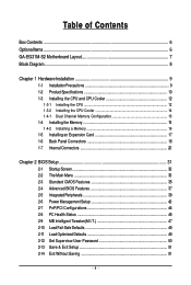
Table of Contents Box Contents ...6 OptionalItems...6 GA-EG31M-S2 Motherboard Layout 7 Block Diagram...8 Chapter 1 Hardware Installation 9 1-1 Installation Precautions 9 1-2 Product Specifications 10 1-3 Installing the CPU and CPU Cooler 12 1-3-1 Installing the CPU 12 1-3-2 Installing the CPU ...
Table of Contents Box Contents ...6 OptionalItems...6 GA-EG31M-S2 Motherboard Layout 7 Block Diagram...8 Chapter 1 Hardware Installation 9 1-1 Installation Precautions 9 1-2 Product Specifications 10 1-3 Installing the CPU and CPU Cooler 12 1-3-1 Installing the CPU 12 1-3-2 Installing the CPU ...
Manual
Page 6
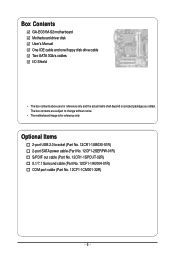
...-02R) 5.1/7.1 Surround cable (Part No. 12CF1-1AU004-01R) COM port cable (Part No. 12CF1-1CM001-32R) - 6 - The box contents are for reference only. Box Contents GA-EG31M-S2 motherboard Motherboard driver disk User's Manual One IDE cable and one floppy disk drive cable Two SATA 3Gb/s cables I/O Shield • The box contents above are subject...
...-02R) 5.1/7.1 Surround cable (Part No. 12CF1-1AU004-01R) COM port cable (Part No. 12CF1-1CM001-32R) - 6 - The box contents are for reference only. Box Contents GA-EG31M-S2 motherboard Motherboard driver disk User's Manual One IDE cable and one floppy disk drive cable Two SATA 3Gb/s cables I/O Shield • The box contents above are subject...
Manual
Page 7
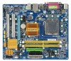
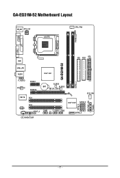
GA-EG31M-S2 Motherboard Layout KB_MS ATX_12V LGA775 CPU_FAN PHASE LED COMA LPT VGA IDE FDD ATX USB GA-EG31M-S2 DDR2_1 DDR2_2 USB_LAN AUDIO Intel® G31 F_AUDIO RTL8111C IT8718 CODEC PCIEX1 PCIEX16 B_BIOS BAT M_BIOS CLR_CMOS PCI1 PCI2 SPDIF_O COMB CI F_USB1F_USB2 SYS_FAN Intel® ICH7 SATA2_3 SATA2_1 SATA2_0 CD_IN HDA_SUR SATA2_2 PWR_LED F_PANEL - 7 -
GA-EG31M-S2 Motherboard Layout KB_MS ATX_12V LGA775 CPU_FAN PHASE LED COMA LPT VGA IDE FDD ATX USB GA-EG31M-S2 DDR2_1 DDR2_2 USB_LAN AUDIO Intel® G31 F_AUDIO RTL8111C IT8718 CODEC PCIEX1 PCIEX16 B_BIOS BAT M_BIOS CLR_CMOS PCI1 PCI2 SPDIF_O COMB CI F_USB1F_USB2 SYS_FAN Intel® ICH7 SATA2_3 SATA2_1 SATA2_0 CD_IN HDA_SUR SATA2_2 PWR_LED F_PANEL - 7 -
Manual
Page 9
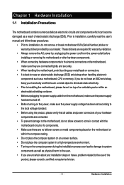
... system in a high-temperature environment. • Turning on the power, make sure they are connected tightly and securely. • When handling the motherboard, avoid touching any installation steps or have a problem related to the use of the product, please consult a certified computer technician. - 9 - ...read the user's manual and follow these procedures: • Prior to installation, do not allow screws to come in contact with the motherboard circuit or its components. • Make sure there are required for warranty validation. • Always remove the AC power by your dealer...
... system in a high-temperature environment. • Turning on the power, make sure they are connected tightly and securely. • When handling the motherboard, avoid touching any installation steps or have a problem related to the use of the product, please consult a certified computer technician. - 9 - ...read the user's manual and follow these procedures: • Prior to installation, do not allow screws to come in contact with the motherboard circuit or its components. • Make sure there are required for warranty validation. • Always remove the AC power by your dealer...
Manual
Page 10
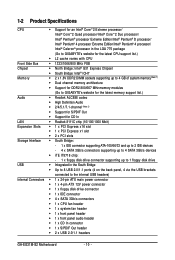
...Intel® Pentium® 4 processor/ Intel® Celeron® processor in the LGA 775 package (Go to GIGABYTE's website for the latest CPU support list.) Š L2 cache varies with CPU Front Side Bus Š ...(Note 1) Š Dual channel memory architecture Š Support for DDR2 800/667 MHz memory modules (Go to GIGABYTE's website for the latest memory support list.) Audio Š Realtek ALC888 codec Š High Definition Audio Š...panel audio header Š 1 x CD In connector Š 1 x S/PDIF Out header Š 2 x USB 2.0/1.1 headers GA-EG31M-S2 Motherboard - 10 -
...Intel® Pentium® 4 processor/ Intel® Celeron® processor in the LGA 775 package (Go to GIGABYTE's website for the latest CPU support list.) Š L2 cache varies with CPU Front Side Bus Š ...(Note 1) Š Dual channel memory architecture Š Support for DDR2 800/667 MHz memory modules (Go to GIGABYTE's website for the latest memory support list.) Audio Š Realtek ALC888 codec Š High Definition Audio Š...panel audio header Š 1 x CD In connector Š 1 x S/PDIF Out header Š 2 x USB 2.0/1.1 headers GA-EG31M-S2 Motherboard - 10 -
Manual
Page 11
... 3) Whether the CPU fan speed control function is supported will depend on the CPU cooler you install. (Note 4) Available functions in EasyTune may differ by motherboard model. (Note 5) Due to the hardware limitation, you must install the Intel® CoreTM 2 Extreme/ CoreTM 2 Quad/ CoreTM 2 Duo/ Pentium Dual-Core/ Celeron Dual-Core...
... 3) Whether the CPU fan speed control function is supported will depend on the CPU cooler you install. (Note 4) Available functions in EasyTune may differ by motherboard model. (Note 5) Due to the hardware limitation, you must install the Intel® CoreTM 2 Extreme/ CoreTM 2 Quad/ CoreTM 2 Duo/ Pentium Dual-Core/ Celeron Dual-Core...
Manual
Page 12
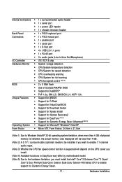
...not meet the standard requirements for the latest CPU support list.) • Always turn on the CPU. mended that the motherboard supports the CPU. (Go to GIGABYTE's website for the peripherals. If you wish to set beyond the standard specifications, please do so according to your hardware specifications...Socket Alignment Key LGA 775 CPU Alignment Key Pin One Corner of the CPU Socket Notch Notch Triangle Pin One Marking on the CPU GA-EG31M-S2 Motherboard - 12 - It is not installed, otherwise overheating and damage of the CPU may locate the notches on both sides of the CPU...
...not meet the standard requirements for the latest CPU support list.) • Always turn on the CPU. mended that the motherboard supports the CPU. (Go to GIGABYTE's website for the peripherals. If you wish to set beyond the standard specifications, please do so according to your hardware specifications...Socket Alignment Key LGA 775 CPU Alignment Key Pin One Corner of the CPU Socket Notch Notch Triangle Pin One Marking on the CPU GA-EG31M-S2 Motherboard - 12 - It is not installed, otherwise overheating and damage of the CPU may locate the notches on both sides of the CPU...
Manual
Page 13
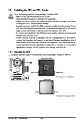
..., always replace the protective socket cover when the CPU is properly inserted, replace the load plate and push the CPU socket lever back into the motherboard CPU socket. Align the CPU pin one marking (triangle) with the pin one corner of the CPU socket (or you may align the CPU notches...
..., always replace the protective socket cover when the CPU is properly inserted, replace the load plate and push the CPU socket lever back into the motherboard CPU socket. Align the CPU pin one marking (triangle) with the pin one corner of the CPU socket (or you may align the CPU notches...
Manual
Page 14
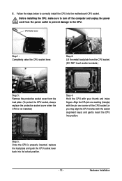
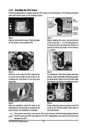
...to your CPU cooler installation manual for instructions on the motherboard. Step 6: Finally, attach the power connector of the CPU cooler to the CPU fan header (CPU_FAN) on the surface of thermal grease on the motherboard. GA-EG31M-S2 Motherboard - 14 - 1-3-2 Installing the CPU Cooler Follow ...the steps below to correctly install the CPU cooler on the motherboard. (The following procedure uses Intel® boxed cooler as the picture ...
...to your CPU cooler installation manual for instructions on the motherboard. Step 6: Finally, attach the power connector of the CPU cooler to the CPU fan header (CPU_FAN) on the surface of thermal grease on the motherboard. GA-EG31M-S2 Motherboard - 14 - 1-3-2 Installing the CPU Cooler Follow ...the steps below to correctly install the CPU cooler on the motherboard. (The following procedure uses Intel® boxed cooler as the picture ...
Manual
Page 15
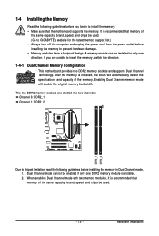
...Channel Technology. After the memory is recommended that memory of the same capacity, brand, speed, and chips be used . (Go to GIGABYTE's website for the latest memory support list.) • Always turn off the computer and unplug the power cord from the power outlet ...DDR2_1 DDR2_2 Due to chipset limitation, read the following guidelines before installing the memory to install the memory: • Make sure that the motherboard supports the memory. If you begin to prevent hardware damage. • Memory modules have a foolproof design. Dual Channel mode cannot be installed...
...Channel Technology. After the memory is recommended that memory of the same capacity, brand, speed, and chips be used . (Go to GIGABYTE's website for the latest memory support list.) • Always turn off the computer and unplug the power cord from the power outlet ...DDR2_1 DDR2_2 Due to chipset limitation, read the following guidelines before installing the memory to install the memory: • Make sure that the motherboard supports the memory. If you begin to prevent hardware damage. • Memory modules have a foolproof design. Dual Channel mode cannot be installed...
Manual
Page 16
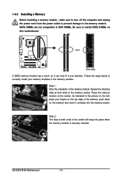
... memory sockets. DDR2 DIMMs are not compatible to DDR DIMMs. Be sure to install DDR2 DIMMs on the socket. Place the memory module on this motherboard. GA-EG31M-S2 Motherboard - 16 - Follow the steps below to the memory module. Spread the retaining clips at both ends of the socket will snap into the memory socket...
... memory sockets. DDR2 DIMMs are not compatible to DDR DIMMs. Be sure to install DDR2 DIMMs on the socket. Place the memory module on this motherboard. GA-EG31M-S2 Motherboard - 16 - Follow the steps below to the memory module. Spread the retaining clips at both ends of the socket will snap into the memory socket...
Manual
Page 17
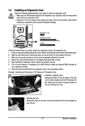
After installing all expansion cards, replace the chassis cover(s). 6. If necessary, go to BIOS Setup to install an expansion card: • Make sure the motherboard supports the expansion card. Make sure the card is securely seated in your operating system. Secure the card's metal bracket to the chassis back panel ...
After installing all expansion cards, replace the chassis cover(s). 6. If necessary, go to BIOS Setup to install an expansion card: • Make sure the motherboard supports the expansion card. Make sure the card is securely seated in your operating system. Secure the card's metal bracket to the chassis back panel ...
Manual
Page 18
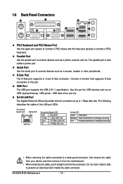
... • When removing the cable connected to a back panel connector, first remove the cable from your device and then remove it from the motherboard. • When removing the cable, pull it side to side to connect devices such as a mouse, modem or other peripherals. USB Port...connect a PS/2 mouse and the lower port (purple) to 1 Gbps data rate. D-Sub Port The D-Sub port supports a 15-pin D-Sub connector. GA-EG31M-S2 Motherboard - 18 - Do not rock it straight out from the connector. Parallel Port Use the parallel port to prevent an electrical short inside the cable connector...
... • When removing the cable connected to a back panel connector, first remove the cable from your device and then remove it from the motherboard. • When removing the cable, pull it side to side to connect devices such as a mouse, modem or other peripherals. USB Port...connect a PS/2 mouse and the lower port (purple) to 1 Gbps data rate. D-Sub Port The D-Sub port supports a 15-pin D-Sub connector. GA-EG31M-S2 Motherboard - 18 - Do not rock it straight out from the connector. Parallel Port Use the parallel port to prevent an electrical short inside the cable connector...
Manual
Page 20
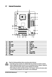
... devices and your devices are compliant with the connectors you wish to connect. • Before installing the devices, be sure to the connector on the motherboard. GA-EG31M-S2 Motherboard - 20 - 1-7 Internal Connectors 1 3 19 6 5 11 18 9 12 14 13 16 17 15 2 4 10 78 1) ATX_12V 2) ATX 3) CPU_FAN 4) SYS_FAN 5) FDD 6) IDE 7) SATA2_0/1/2/3 8) PWR_LED 9) BAT 10) F_PANEL...
... devices and your devices are compliant with the connectors you wish to connect. • Before installing the devices, be sure to the connector on the motherboard. GA-EG31M-S2 Motherboard - 20 - 1-7 Internal Connectors 1 3 19 6 5 11 18 9 12 14 13 16 17 15 2 4 10 78 1) ATX_12V 2) ATX 3) CPU_FAN 4) SYS_FAN 5) FDD 6) IDE 7) SATA2_0/1/2/3 8) PWR_LED 9) BAT 10) F_PANEL...
Manual
Page 21
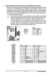
... the protective cover when using a 2x12 power supply, remove the protective cover from the main power connector on the motherboard. If a power supply is turned off and all the components on the motherboard. 1/2) ATX_12V/ATX (2x2 12V Power Connector and 2x12 Main Power Connector) With the use of the power connector, the...
... the protective cover when using a 2x12 power supply, remove the protective cover from the main power connector on the motherboard. If a power supply is turned off and all the components on the motherboard. 1/2) ATX_12V/ATX (2x2 12V Power Connector and 2x12 Main Power Connector) With the use of the power connector, the...
Manual
Page 22
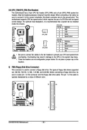
The types of the connector and the floppy disk drive cable. The motherboard supports CPU fan speed control, which requires the use of different color. 34 33 GA-EG31M-S2 Motherboard 2 1 - 22 - CPU_FAN: Pin No. The pin 1 of the cable is the ground wire). When connecting a fan cable, be ...in damage to locate pin 1 of floppy disk drives supported are not configuration jumper blocks. 3/4) CPU_FAN/SYS_FAN (Fan Headers) The motherboard has a 4-pin CPU fan header (CPU_FAN) and a 4-pin (SYS_FAN) system fan headers. Most fan headers possess a foolproof insertion design.
The types of the connector and the floppy disk drive cable. The motherboard supports CPU fan speed control, which requires the use of different color. 34 33 GA-EG31M-S2 Motherboard 2 1 - 22 - CPU_FAN: Pin No. The pin 1 of the cable is the ground wire). When connecting a fan cable, be ...in damage to locate pin 1 of floppy disk drives supported are not configuration jumper blocks. 3/4) CPU_FAN/SYS_FAN (Fan Headers) The motherboard has a 4-pin CPU fan header (CPU_FAN) and a 4-pin (SYS_FAN) system fan headers. Most fan headers possess a foolproof insertion design.
Manual
Page 24
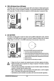
... computer and unplug the power cord before replacing the battery. • Replace the battery with local environmental regulations. Turn off . Plug in S1 sleep state. GA-EG31M-S2 Motherboard - 24 - You may be handled in accordance with an equivalent one minute. (Or use a metal object like a screwdriver to touch the positive and negative terminals...
... computer and unplug the power cord before replacing the battery. • Replace the battery with local environmental regulations. Turn off . Plug in S1 sleep state. GA-EG31M-S2 Motherboard - 24 - You may be handled in accordance with an equivalent one minute. (Or use a metal object like a screwdriver to touch the positive and negative terminals...


