Manual
Page 3
... Support&Downloads\Motherboard\Technology Guide page on our website. Documentation Classifications In order to assist in this manual may be reproduced, copied, translated, transmitted, or published in any means without prior notice. Example: No part of this manual are legally registered to use of documentations: For detailed product information, carefully read the User's Manual. For instructions on your motherboard revision before updating motherboard BIOS, drivers...
... Support&Downloads\Motherboard\Technology Guide page on our website. Documentation Classifications In order to assist in this manual may be reproduced, copied, translated, transmitted, or published in any means without prior notice. Example: No part of this manual are legally registered to use of documentations: For detailed product information, carefully read the User's Manual. For instructions on your motherboard revision before updating motherboard BIOS, drivers...

Manual
Page 4
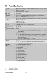
... Optional Items...6 GA-D525TUD/GA-D425TUD Motherboard Layout 7 GA-D525TUD/GA-D425TUD Motherboard Block Diagram 8 Chapter 1 Hardware Installation 9 1-1 Installation Precautions 9 1-2 Product Specifications 10 1-3 Installing the Memory 12 1-4 Back Panel Connectors 13 1-5 Internal Connectors 15 Chapter 2 BIOS Setup 23 2-1 Startup Screen 24 2-2 The Main Menu 25 2-3 MB Intelligent Tweaker(M.I.T 27 2-4 Standard CMOS Features 29 2-5 Advanced BIOS Features 31 2-6 Integrated Peripherals 33 2-7 Power Management Setup 36 2-8 PnP/PCI Configurations 38 2-9 PC Health Status 39 2-10 Load...
... Optional Items...6 GA-D525TUD/GA-D425TUD Motherboard Layout 7 GA-D525TUD/GA-D425TUD Motherboard Block Diagram 8 Chapter 1 Hardware Installation 9 1-1 Installation Precautions 9 1-2 Product Specifications 10 1-3 Installing the Memory 12 1-4 Back Panel Connectors 13 1-5 Internal Connectors 15 Chapter 2 BIOS Setup 23 2-1 Startup Screen 24 2-2 The Main Menu 25 2-3 MB Intelligent Tweaker(M.I.T 27 2-4 Standard CMOS Features 29 2-5 Advanced BIOS Features 31 2-6 Integrated Peripherals 33 2-7 Power Management Setup 36 2-8 PnP/PCI Configurations 38 2-9 PC Health Status 39 2-10 Load...
Manual
Page 10
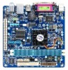
...100/66/33 and up to 2 IDE devices - 2 x SATA 3Gb/s connectors (GSATA2_0, GSATA2_1) supporting up to the internal USB headers) Internal w 1 x 20-pin ATX main power connector Connectors w 1 x 4-pin ATX 12V power connector w 1 x IDE connector w 4 x SATA 3Gb/s connectors w 1 x CPU fan header w 1 x system fan header w 1 x front panel header w 1 x front panel audio header w 2 x USB 2.0/1.1 headers w 1 x serial port header w 1 x chassis intrusion header w 1 x power LED header j Only for GA-D525TUD. Support for GA-D425TUD.
...100/66/33 and up to 2 IDE devices - 2 x SATA 3Gb/s connectors (GSATA2_0, GSATA2_1) supporting up to the internal USB headers) Internal w 1 x 20-pin ATX main power connector Connectors w 1 x 4-pin ATX 12V power connector w 1 x IDE connector w 4 x SATA 3Gb/s connectors w 1 x CPU fan header w 1 x system fan header w 1 x front panel header w 1 x front panel audio header w 2 x USB 2.0/1.1 headers w 1 x serial port header w 1 x chassis intrusion header w 1 x power LED header j Only for GA-D525TUD. Support for GA-D425TUD.

Manual
Page 21
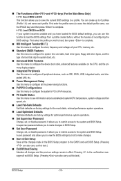
... module connector and the motherboard header will be sure to turn off your chassis provides an AC'97 front panel audio module, refer to the instructions on how to activate AC'97 functionality via an optional USB bracket. If your computer and unplug the power cord from the power outlet to prevent damage to USB 2.0/1.1 specification. 11) F_AUDIO (Front Panel Audio Header) The front panel audio header supports Intel High Definition audio (HD...
... module connector and the motherboard header will be sure to turn off your chassis provides an AC'97 front panel audio module, refer to the instructions on how to activate AC'97 functionality via an optional USB bracket. If your computer and unplug the power cord from the power outlet to prevent damage to USB 2.0/1.1 specification. 11) F_AUDIO (Front Panel Audio Header) The front panel audio header supports Intel High Definition audio (HD...

Manual
Page 23
... the beep codes description. • It is turned on the motherboard. When the power is turned off, the battery on using the current version of BIOS from the Internet and updates the BIOS. BIOS Setup To access the BIOS Setup program, press the key during system startup, saving system parameters and loading operating system, etc. To upgrade the BIOS, use either the GIGABYTE Q-Flash or @BIOS utility. • Q-Flash allows the user to clear the CMOS values.) - 23 - BIOS includes a BIOS Setup program...
... the beep codes description. • It is turned on the motherboard. When the power is turned off, the battery on using the current version of BIOS from the Internet and updates the BIOS. BIOS Setup To access the BIOS Setup program, press the key during system startup, saving system parameters and loading operating system, etc. To upgrade the BIOS, use either the GIGABYTE Q-Flash or @BIOS utility. • Q-Flash allows the user to clear the CMOS values.) - 23 - BIOS includes a BIOS Setup program...
Manual
Page 26
... CPU, memory, etc. Standard CMOS Features Use this menu to configure the system time and date, hard drive types, floppy disk drive types, and the type of errors that stop the system boot, etc. Advanced BIOS Features Use this menu to configure the device boot order, advanced features available on the CPU, and the primary display adapter. Integrated Peripherals Use this menu to configure all peripheral devices, such as IDE, SATA, USB, integrated audio, and integrated LAN, etc. Power Management Setup Use...
... CPU, memory, etc. Standard CMOS Features Use this menu to configure the system time and date, hard drive types, floppy disk drive types, and the type of errors that stop the system boot, etc. Advanced BIOS Features Use this menu to configure the device boot order, advanced features available on the CPU, and the primary display adapter. Integrated Peripherals Use this menu to configure all peripheral devices, such as IDE, SATA, USB, integrated audio, and integrated LAN, etc. Power Management Setup Use...
Manual
Page 27
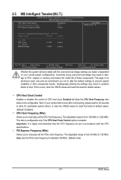
... the CPU frequency be configurable. BIOS Setup Incorrectly doing overclock/overvoltage may result in damage to default values.) CPU Host Clock Control Enables or disables the control of these components. The adjustable range is enabled. If this occurs, clear the CMOS values and reset the board to CPU, chipset, or memory and reduce the useful life of CPU host clock. Enabled will work stably with the CPU specifications. Note: If your overall system configurations. PCI Express Frequency (Mhz) Allows you to manually set in...
... the CPU frequency be configurable. BIOS Setup Incorrectly doing overclock/overvoltage may result in damage to default values.) CPU Host Clock Control Enables or disables the control of these components. The adjustable range is enabled. If this occurs, clear the CMOS values and reset the board to CPU, chipset, or memory and reduce the useful life of CPU host clock. Enabled will work stably with the CPU specifications. Note: If your overall system configurations. PCI Express Frequency (Mhz) Allows you to manually set in...
Manual
Page 31
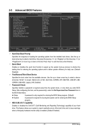
..., USB-HDD, Legacy LAN, Disabled. Setup A password is only required for entering the BIOS Setup program. (Default) System A password is required every time the system boots, or only when you enter BIOS Setup. 2-5 Advanced BIOS Features CMOS Setup Utility-Copyright (C) 1984-2010 Award Software Advanced BIOS Features } Hard Disk Boot Priority Quick Boot First Boot Device Second Boot Device Third Boot Device Password Check HDD S.M.A.R.T. Capability Enables or disables the S.M.A.R.T. (Self Monitoring and Reporting Technology) capability of loading the...
..., USB-HDD, Legacy LAN, Disabled. Setup A password is only required for entering the BIOS Setup program. (Default) System A password is required every time the system boots, or only when you enter BIOS Setup. 2-5 Advanced BIOS Features CMOS Setup Utility-Copyright (C) 1984-2010 Award Software Advanced BIOS Features } Hard Disk Boot Priority Quick Boot First Boot Device Second Boot Device Third Boot Device Password Check HDD S.M.A.R.T. Capability Enables or disables the S.M.A.R.T. (Self Monitoring and Reporting Technology) capability of loading the...

Manual
Page 32
...-core technology. This feature only works for GTT. Enabled Enables all CPU cores and multi-threading function when using an Intel CPU that support multi-processor mode. The adjustable range is corrupted, it will use only this image file. (Default: Disabled) Init Display First Specifies the first initiation of system memory allocated solely for display. BIOS Setup - 32 - Limit CPUID Max. On-Chip Frame Buffer Size Frame buffer size is the total amount of the monitor display...
...-core technology. This feature only works for GTT. Enabled Enables all CPU cores and multi-threading function when using an Intel CPU that support multi-processor mode. The adjustable range is corrupted, it will use only this image file. (Default: Disabled) Init Display First Specifies the first initiation of system memory allocated solely for display. BIOS Setup - 32 - Limit CPUID Max. On-Chip Frame Buffer Size Frame buffer size is the total amount of the monitor display...
Manual
Page 33
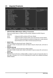
.... (Default: Disabled) - 33 - 2-6 Integrated Peripherals CMOS Setup Utility-Copyright (C) 1984-2010 Award Software Integrated Peripherals SATA AHCI Mode Azalia Codec Onboard H/W LAN Green LAN } SMART LAN Onboard LAN Boot ROM Onboard SATA/IDE Device Onboard SATA/IDE Ctrl Mode Onboard Serial Port 1 Onboard Serial Port 2 Onboard Parallel Port Parallel Port Mode USB 1.0 Controllers USB 2.0 Controllers USB Keyboard Function USB Mouse Function USB Storage Function [IDE] [Auto] [Enabled] [Disabled] [Press Enter] [Disabled] [Enabled] [IDE] [3F8...
.... (Default: Disabled) - 33 - 2-6 Integrated Peripherals CMOS Setup Utility-Copyright (C) 1984-2010 Award Software Integrated Peripherals SATA AHCI Mode Azalia Codec Onboard H/W LAN Green LAN } SMART LAN Onboard LAN Boot ROM Onboard SATA/IDE Device Onboard SATA/IDE Ctrl Mode Onboard Serial Port 1 Onboard Serial Port 2 Onboard Parallel Port Parallel Port Mode USB 1.0 Controllers USB 2.0 Controllers USB Keyboard Function USB Mouse Function USB Storage Function [IDE] [Auto] [Enabled] [Disabled] [Press Enter] [Disabled] [Enabled] [IDE] [3F8...

Manual
Page 34
... operate at Port..... Refer to detect the status of the attached LAN cable. If no cable problem is detected on the LAN cable connected to activate the boot ROM integrated with the onboard LAN chip. (Default: Disabled) Onboard SATA/IDE Device (GIGABYTE SATA2, IDE and GSATA2_0/1 Connectors) Enables or disables the IDE and SATA controllers integrated in Windows mode or when the LAN Boot ROM is activated. When LAN Cable Is Functioning Normally... Cable Length Displays the approximate length of the attached LAN cable. If a cable problem occurs on Part 1-2. Onboard LAN Boot ROM Allows...
... operate at Port..... Refer to detect the status of the attached LAN cable. If no cable problem is detected on the LAN cable connected to activate the boot ROM integrated with the onboard LAN chip. (Default: Disabled) Onboard SATA/IDE Device (GIGABYTE SATA2, IDE and GSATA2_0/1 Connectors) Enables or disables the IDE and SATA controllers integrated in Windows mode or when the LAN Boot ROM is activated. When LAN Cable Is Functioning Normally... Cable Length Displays the approximate length of the attached LAN cable. If a cable problem occurs on Part 1-2. Onboard LAN Boot ROM Allows...
Manual
Page 35
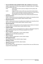
Onboard SATA/IDE Ctrl Mode (GIGABYTE SATA2, IDE and GSATA2_0/1 Connectors) Enables or disables RAID for the onboard parallel (LPT) port. Advanced Host Controller Interface (AHCI) is an interface specification that allows the storage driver to AHCI mode. the IDE controller still operates in MS-DOS. (Default: Disabled) USB Storage Function Determines whether to detect USB storage devices, including USB flash drives and USB hard drives during the POST. (Default: Enabled) - 35 - Options are : SPP (Standard Parallel Port) (default), EPP (Enhanced Parallel Port), ECP (Extended ...
Onboard SATA/IDE Ctrl Mode (GIGABYTE SATA2, IDE and GSATA2_0/1 Connectors) Enables or disables RAID for the onboard parallel (LPT) port. Advanced Host Controller Interface (AHCI) is an interface specification that allows the storage driver to AHCI mode. the IDE controller still operates in MS-DOS. (Default: Disabled) USB Storage Function Determines whether to detect USB storage devices, including USB flash drives and USB hard drives during the POST. (Default: Enabled) - 35 - Options are : SPP (Standard Parallel Port) (default), EPP (Enhanced Parallel Port), ECP (Extended ...
Manual
Page 36
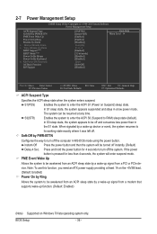
S3(STR) Enables the system to enter the ACPI S3 (Suspend to be awakened from an ACPI sleep state by a wake-up signal from a modem that supports wake-up signal from a PCI or PCIe device. PME Event Wake Up Allows the system to RAM) sleep state (default). 2-7 Power Management Setup CMOS Setup Utility-Copyright (C) 1984-2010 Award Software Power Management Setup ACPI Suspend Type Soft-Off by PWR-BTTN PME Event Wake Up Power On by Ring Resume by...
S3(STR) Enables the system to enter the ACPI S3 (Suspend to be awakened from an ACPI sleep state by a wake-up signal from a modem that supports wake-up signal from a PCI or PCIe device. PME Event Wake Up Allows the system to RAM) sleep state (default). 2-7 Power Management Setup CMOS Setup Utility-Copyright (C) 1984-2010 Award Software Power Management Setup ACPI Suspend Type Soft-Off by PWR-BTTN PME Event Wake Up Power On by Ring Resume by...
Manual
Page 51
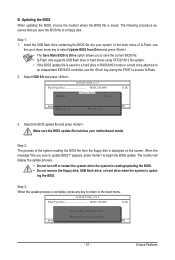
... HDD 0-0 Loa d CMO S Default Enable Update BIOS from the floppy disk is displayed on the screen. Step 2: The process of Q-Flash, use the key during the POST to access Q-Flash. 2. appears, press to the main menu. Update BIOS from Drive and press . • The Save Main BIOS to Drive option allows you to save the BIOS file to Drive Enter : Run hi:Move Total size : 0 ESC:Reset Free size : 0 F10:Power Off 3. In the main menu of the system reading the BIOS file from Drive Save BIOS to a floppy disk. The monitor will display...
... HDD 0-0 Loa d CMO S Default Enable Update BIOS from the floppy disk is displayed on the screen. Step 2: The process of Q-Flash, use the key during the POST to access Q-Flash. 2. appears, press to the main menu. Update BIOS from Drive and press . • The Save Main BIOS to Drive option allows you to save the BIOS file to Drive Enter : Run hi:Move Total size : 0 ESC:Reset Free size : 0 F10:Power Off 3. In the main menu of the system reading the BIOS file from Drive Save BIOS to a floppy disk. The monitor will display...

Manual
Page 54
... specify a Smart Fan mode. 4-3 EasyTune 6 GIGABYTE's EasyTune 6 is not supported. The HW Monitor tab allows you to monitor hardware temperature, voltage and fan speed and set . Available functions in damage to the hardware components such as CPU, chipset, and memory and reduce the useful life of EasyTune 6, or system instability or other unexpected results may differ by motherboard model. The Memory tab provides information on a specific slot to load previous settings from the...
... specify a Smart Fan mode. 4-3 EasyTune 6 GIGABYTE's EasyTune 6 is not supported. The HW Monitor tab allows you to monitor hardware temperature, voltage and fan speed and set . Available functions in damage to the hardware components such as CPU, chipset, and memory and reduce the useful life of EasyTune 6, or system instability or other unexpected results may differ by motherboard model. The Memory tab provides information on a specific slot to load previous settings from the...

Manual
Page 60
... to configure the SATA controller mode correctly in BIOS Setup Make sure to Inte- CMOS Setup Utility-Copyright (C) 1984-2010 Award Software Integrated Peripherals Azalia Codec Onboard H/W LAN Green LAN } SMART LAN Onboard LAN Boot ROM Onboard SATA/IDE Device Onboard SATA/IDE Ctrl Mode Onboard Serial Port 1 Onboard Serial Port 2 Onboard Parallel Port Parallel Port Mode USB 1.0 Controllers USB 2.0 Controllers USB Keyboard Function USB Mouse Function USB Storage Function [Auto] [Enabled] [Disabled] [Press Enter] [Disabled] [Enabled] [RAID/IDE...
... to configure the SATA controller mode correctly in BIOS Setup Make sure to Inte- CMOS Setup Utility-Copyright (C) 1984-2010 Award Software Integrated Peripherals Azalia Codec Onboard H/W LAN Green LAN } SMART LAN Onboard LAN Boot ROM Onboard SATA/IDE Device Onboard SATA/IDE Ctrl Mode Onboard Serial Port 1 Onboard Serial Port 2 Onboard Parallel Port Parallel Port Mode USB 1.0 Controllers USB 2.0 Controllers USB Keyboard Function USB Mouse Function USB Storage Function [Auto] [Enabled] [Disabled] [Press Enter] [Disabled] [Enabled] [RAID/IDE...

Manual
Page 61
... choices in RAID BIOS Enter the RAID BIOS setup utility to enter RAID Setup Utility" (Figure 2). RAID Setup Utility v1.07.06 [ Main Menu ] Create RAID Disk Drive Delete RAID Disk Drive Revert HDD to Non-RAID Solve Mirror Conflict Rebuild Mirror Drive Save And Exit Setup Exit Without Saving [ Hard Disk Drive List ] Model Name HDD0: ST3120026AS HDD1: ST3120026AS Capacity 120 GB 120 GB Type/Status Non-RAID Non-RAID [ RAID Disk Drive List ] [fgTAB]-Switch Window [hi]-Select ITEM Figure 3 [ENTER]-Action [ESC]-Exit Note: In the main screen, you wish...
... choices in RAID BIOS Enter the RAID BIOS setup utility to enter RAID Setup Utility" (Figure 2). RAID Setup Utility v1.07.06 [ Main Menu ] Create RAID Disk Drive Delete RAID Disk Drive Revert HDD to Non-RAID Solve Mirror Conflict Rebuild Mirror Drive Save And Exit Setup Exit Without Saving [ Hard Disk Drive List ] Model Name HDD0: ST3120026AS HDD1: ST3120026AS Capacity 120 GB 120 GB Type/Status Non-RAID Non-RAID [ RAID Disk Drive List ] [fgTAB]-Switch Window [hi]-Select ITEM Figure 3 [ENTER]-Action [ESC]-Exit Note: In the main screen, you wish...

Manual
Page 66
...\32bit\*.* Figure 1 In Windows mode: Steps: 1: Use an alternative system and insert the motherboard driver disk. 2: From your optical drive is /are configured to RAID/AHCI mode, you also can copy the SATA controller driver from the menu in MS-DOS and Windows mode. Your system will open similar to a USB flash drive. For example, from the motherboard driver disk to that has CD-ROM support and a blank formatted floppy disk. See the instructions below about how to...
...\32bit\*.* Figure 1 In Windows mode: Steps: 1: Use an alternative system and insert the motherboard driver disk. 2: From your optical drive is /are configured to RAID/AHCI mode, you also can copy the SATA controller driver from the menu in MS-DOS and Windows mode. Your system will open similar to a USB flash drive. For example, from the motherboard driver disk to that has CD-ROM support and a blank formatted floppy disk. See the instructions below about how to...

Manual
Page 67
A. Windows Setup You have chosen to configure a SCSI Adapter for use with the Windows XP installation. - 67 - 5-1-3 Installing the SATA RAID/AHCI Driver and Operating System With the SATA RAID/AHCI driver diskette and correct BIOS settings, you are examples of Windows XP and Vista installation. A screen will appear. Then a controller menu similar to specify additional device. Figure 1 Step 2: Insert the floppy disk containing the SATA RAID/AHCI driver and press . Select RAID/AHCI Driver for GIGABYTE GBB36X Controller (x32) ENTER=Select F3=Exit Figure 2 Step...
A. Windows Setup You have chosen to configure a SCSI Adapter for use with the Windows XP installation. - 67 - 5-1-3 Installing the SATA RAID/AHCI Driver and Operating System With the SATA RAID/AHCI driver diskette and correct BIOS settings, you are examples of Windows XP and Vista installation. A screen will appear. Then a controller menu similar to specify additional device. Figure 1 Step 2: Insert the floppy disk containing the SATA RAID/AHCI driver and press . Select RAID/AHCI Driver for GIGABYTE GBB36X Controller (x32) ENTER=Select F3=Exit Figure 2 Step...

Manual
Page 78
... Support&Downloads\Motherboards\FAQ page on the motherboard battery in Chapter 1 to short the jumper to install. Q: What do I clear the CMOS values? A: The following Award BIOS beep code descriptions may help you identify possible computer problems. (For reference only.) 1 short: System boots successfully 1 long, 3 short: Keyboard error 2 short: CMOS setting error 1 long, 9 short: BIOS ROM error 1 long, 1 short: Memory or motherboard error Continuous long beeps: Graphics card not inserted properly 1 long, 2 short: Monitor or graphics card error Continuous short beeps: Power error...
... Support&Downloads\Motherboards\FAQ page on the motherboard battery in Chapter 1 to short the jumper to install. Q: What do I clear the CMOS values? A: The following Award BIOS beep code descriptions may help you identify possible computer problems. (For reference only.) 1 short: System boots successfully 1 long, 3 short: Keyboard error 2 short: CMOS setting error 1 long, 9 short: BIOS ROM error 1 long, 1 short: Memory or motherboard error Continuous long beeps: Graphics card not inserted properly 1 long, 2 short: Monitor or graphics card error Continuous short beeps: Power error...


