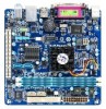
Gigabyte GA-D525TUD Support Question
Gigabyte GA-D525TUD Support Question
Find answers below for this question about Gigabyte GA-D525TUD.Need a Gigabyte GA-D525TUD manual? We have 1 online manual for this item!
Question posted by peter26516 on February 5th, 2015
No 5v Power For Mic On Rear Jack
Hi, I can't get my microphone working on this board. I've narrowed it down to the fact that the board doesn't supply the standard 5V that those standard electret microphones require. There is no hint in the manual, i.e. there doesn't appear to be a jumper on the board that can be used to configure that. Can I switch that on somehow? For this particular mic I'll need it on the tip of the connector. Thanks kindly for your help! Peter
Current Answers
Related Gigabyte GA-D525TUD Manual Pages
Manual - Page 4

...GA-D525TUD/GA-D425TUD Motherboard Layout 7 GA-D525TUD/GA-D425TUD Motherboard Block Diagram 8
Chapter 1 Hardware Installation 9 1-1 Installation Precautions 9 1-2 Product Specifications 10 1-3 Installing the Memory 12 1-4 Back Panel Connectors 13 1-5 Internal Connectors 15
Chapter 2 BIOS Setup 23 2-1 Startup Screen 24 2-2 The Main Menu 25 2-3 MB Intelligent Tweaker(M.I.T 27 2-4 Standard...
Manual - Page 6

Optional Items
2-port USB 2.0 bracket (Part No. 12CR1-1UB030-5*R) 2-port SATA power cable (Part No. 12CF1-2SERPW-0*R) COM port cable (Part No. 12CF1-1CM001-3*R)
- 6 - The box contents are for reference only. Box Contents
GA-D525TUD or GA-D425TUD motherboard Motherboard driver disk User's Manual One IDE cable One SATA cable I/O Shield
• The box contents above are subject...
Manual - Page 7
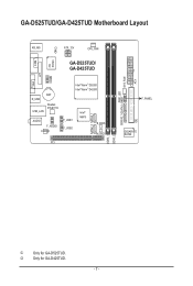
GA-D525TUD/GA-D425TUD Motherboard Layout
COM
KB_MS
iTE IT8720
CI
ATX_12V
CPU_FAN
GA-D525TUD/ GA-D425TUD
LPT
COMB
VGA
BAT R_USB
Realtek RTL8111E USB_LAN
AUDIO F_AUDIO
CODEC
Intel® Atom™ D525j Intel® Atom™ D425k
F_USB1 F_USB2
Intel&#...
Manual - Page 8

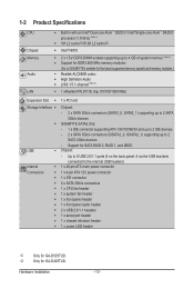
GA-D525TUD/GA-D425TUD Motherboard Block Diagram
D-Sub
Intel® Atom™
CPU
CPU CLK+/- (200 MHz)
DDR3 800 MHz Memory
DMI Interface
LAN
RJ45
PCIe CLK... SATA2
PCI Bus
Dual BIOS 2 SATA 3Gb/s 8 USB 2.0/1.1
iTE LPC Bus IT8720
LPT Port COM Ports
CODEC
PS/2 KB/Mouse
MIC (Center/Subwoofer Speaker Out) Line-Out (Front Speaker Out) Line-In (Rear Speaker Out)
1 PCI
PCI CLK (33 MHz)
- 8 -
Manual - Page 9

... prevent damage to the motherboard, do not remove or break motherboard S/N (Serial Number) sticker or warranty sticker provided by unplugging the power cord from the motherboard, make sure the power supply has been turned off. • Before turning on the motherboard, make sure the power supply voltage has been set according to the local voltage standard. • Before using the...
Manual - Page 10
...; NM10
2 x 1.5V DDR3 DIMM sockets supporting ...power connector w 1 x IDE connector w 4 x SATA 3Gb/s connectors w 1 x CPU fan header w 1 x system fan header w 1 x front panel header w 1 x front panel audio header w 2 x USB 2.0/1.1 headers w 1 x serial port header w 1 x chassis intrusion header w 1 x power LED header
j Only for GA-D525TUD...
Manual - Page 11

...port w 1 x serial port w 1 x D-Sub port w 4 x USB 2.0/1.1 ports w 1 x RJ-45 port w 3 x audio jacks (Line In/Line Out/Microphone)
w iTE IT8720 chip
Hardware Monitor w w w w
BIOS w w w w
Unique Features w w w w w w w
w w ... driver. (Note 4) Available functions in EasyTune may differ by motherboard model.
- 11 -
Manual - Page 12
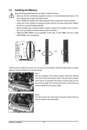
...supported memory speeds and memory modules.) • Always turn off the computer and unplug the power cord from the power outlet before you are unable to insert the memory, switch the direction. • DDR3 ... top edge of the memory module.
Follow the steps below to install DDR3 DIMMs on this motherboard.
Step 1: Note the orientation of the memory, push down on the memory and insert it...
Manual - Page 14

...) The default line in jack.
This jack can be connected to this jack. To configure 7.1-channel audio, you need connect with the port of HD Audio standard via front panel and enable the multi-channel audio feature through the audio driver. Refer to connect front speakers in a 4/5.1/7.1-channel audio configuration. Microphones must be used to...
Manual - Page 15

Unplug the
power cord from the power outlet to prevent damage to the devices. • After installing the device and before connecting external devices: • First make sure the device cable ...4) SYS_FAN 5) IDE 6) SATA2_0/1 7) GSATA2_0/1
8) PWR_LED 9) BAT 10) F_PANEL 11) F_AUDIO 12) F_USB1/F_USB2 13) COMB 14) CI
Read the following guidelines before turning on the motherboard.
- 15 -
Manual - Page 16

... connector is turned off and all the components on the motherboard. The 12V power connector mainly supplies power to the power connector in the correct orientation. Connect the power supply cable to the CPU. Before connecting the power connector, first make sure the power supply is not connected, the computer will not start.
3
4
1
2
ATX_12V
ATX_12V: Pin No. 1 2 3 4
Definition GND...
Manual - Page 21

... default. If your computer and unplug the power
cord from the power outlet to prevent damage to work or even damage it.
Definition
For AC'97 Front Panel Audio: Pin No. For purchasing the optional USB bracket, please contact the local dealer.
10
9
2
1
Pin No. 1 2 3 4 5 6 7 8 9 10
Definition Power (5V) Power (5V) USB DXUSB DYUSB DX+ USB DY...
Manual - Page 23

...board to default values. (Refer to the "Load Optimized Defaults" section in this chapter or introductions of the battery/ clearing CMOS jumper in Chapter 1 for the beep codes description.
• It is turned on the motherboard. To access the BIOS Setup program, press the key during the POST when the power... For instructions on the motherboard supplies the necessary power to the CMOS to ...
Manual - Page 25

... the items and press to accept or enter a sub-menu. (Sample BIOS Version: GA-D525TUD E10c)
CMOS Setup Utility-Copyright (C) 1984-2010 Award Software
MB Intelligent Tweaker(M.I.T.) Standard CMOS Features Advanced BIOS Features Integrated Peripherals Power Management Setup PnP/PCI Configurations PC Health Status
Load Fail-Safe...
Manual - Page 60

...the rear of the SATA hard drive and the other end to available SATA port on your computer and press to RAID/IDE (Figure 1).
Step 1:
Turn on the motherboard....motherboard, the GSATA2_0 and GSATA2_1 ports are supported by the GIGABYTE SATA2 SATA controller.
Then set this item to the hard drive. Then connect the power connector from the exact settings for your power supply...
Manual - Page 72

... In Front Speaker Out Mic In
• To install a microphone, connect your microphone to the right shows the default audio jack assignments. High Definition Audio (HD Audio) HD Audio includes multiple high quality digital-to change the function for microphone functionality.
• Audio signals will appear in jack and manually configure the jack for each jack through the audio...
Manual - Page 73

..., 5.1 Speaker, or 7.1 Speaker according to the type of device you wish to an audio jack. The The current connected device is completed. The pictures to the right show the 7.1-channel speaker configurations.
7.1-Channel Speakers:
Front Speaker Out
Rear Speaker Out
Center/Subwoofer Speaker Out
Step 2: Connect an audio device to set up...
Manual - Page 74

Appendix
- 74 - Select the Mute the rear output device, when a front headphone plugged in check box. Click OK to complete. Click OK to... audio module, to open the Device advanced settings dialog box. On the Connector Settings dialog box, select the Disable front panel jack detection check box. C. D. Muting the Back Panel Audio (For HD Audio Only) Click Device advanced settings on the top ...
Manual - Page 75

... during the recording process, do not mute the playback volume.
Step 3: Go to the Mic in jack (pink) on Microphone and select Set Default Device.
- 75 - Double-click the icon to microphone, right-click on the back panel or the Mic in the notification area. If you 'll not be used at a middle level. It...
Manual - Page 79
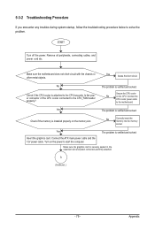
... and solved. Insert the graphics card.
No Check if the CPU cooler is securely seated in the expansion slot and power connectors are firmly attached. START
Turn off the power. Make sure the motherboard does not short-circuit with the chassis or other metal objects. Yes
The problem is verified and solved.
A (Continued...
Similar Questions

How To Manually Overclock Gigabyte Motherboard Ga-970a-ud3
(Posted by mk45Snowfl 9 years ago)


Gigabyte Motherboard Ga-h55-usb3 (rev. 2.0)
what is the price in INR and from where purchase in india local or online.
what is the price in INR and from where purchase in india local or online.
(Posted by shailkam2001 11 years ago)
Pls. Send Me A Pdf Wiring Installation Guide For My Motherboard Ga-h61m-ds2..thn
(Posted by DAVIDJR1261 11 years ago)
Why My Motherboard Ga-g31m-es2l Not Sporting Any Game
(Posted by camonurai 12 years ago)