Manual
Page 1
GA-965P-DS3P Intel® CoreTM 2 Extreme quad-core / CoreTM 2 Quad / Intel® CoreTM 2 Extreme dual-core / CoreTM 2 Duo / Intel® Pentium® Processor Extreme Edition / Intel® Pentium® D / Pentium® 4 LGA775 Processor Motherboard User's Manual Rev. 3301 12ME-965PDS3P-3301R * The WEEE marking on the product indicates this product must not be disposed...
GA-965P-DS3P Intel® CoreTM 2 Extreme quad-core / CoreTM 2 Quad / Intel® CoreTM 2 Extreme dual-core / CoreTM 2 Duo / Intel® Pentium® Processor Extreme Edition / Intel® Pentium® D / Pentium® 4 LGA775 Processor Motherboard User's Manual Rev. 3301 12ME-965PDS3P-3301R * The WEEE marking on the product indicates this product must not be disposed...
Manual
Page 2
Motherboard GA-965P-DS3P Nov. 10, 2006 Motherboard GA-965P-DS3P Nov. 10, 2006
Motherboard GA-965P-DS3P Nov. 10, 2006 Motherboard GA-965P-DS3P Nov. 10, 2006
Manual
Page 4
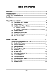
Table of Contents ItemChecklist ...6 OptionalAccessories ...6 GA-965P-DS3P Motherboard Layout 7 Block Diagram ...8 Chapter 1 Hardware Installation 9 1-1 Considerations Prior to Installation 9 1-2 Feature Summary 10 1-3 Installation of the CPU and CPU Cooler 13 1-3-1 Installation of the CPU ...
Table of Contents ItemChecklist ...6 OptionalAccessories ...6 GA-965P-DS3P Motherboard Layout 7 Block Diagram ...8 Chapter 1 Hardware Installation 9 1-1 Considerations Prior to Installation 9 1-2 Feature Summary 10 1-3 Installation of the CPU and CPU Cooler 13 1-3-1 Installation of the CPU ...
Manual
Page 7
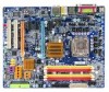
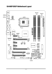
GA-965P-DS3P Motherboard Layout KB_MS COAXIAL OPTICAL ATX_12V_2X LGA775 PWR_FAN PCIE_12V ATX COM LPT 1394 USB GA-965P-DS3P LAN USB AUDIO BATTERY CPU_FAN CLR_CMOS Intel® P965 F_AUDIO PCIE_1 FDD Marvell 8053 PCIE_16_1 NB_FAN DDRII1 DDRII2 DDRII3 DDRII4 PCIE_2 CODEC PCIE_3 CD_IN PCIE_16_2 PCI1 IT8718 PCI2 SPDIF_IN BACKUP MAIN BIOS BIOS CI TSB43AB23 SYS_FAN F1_1394 SATAII0 Intel® ICH8R SATAII4 SATAII1 SATAII2 SATAII5 SATAII3 GIGABYTE SATA2 IDE GSATAII1 GSATAII0 F_USB1 F_USB2 F_USB3 PWR_LED F_PANEL F2_1394 - 7 -
GA-965P-DS3P Motherboard Layout KB_MS COAXIAL OPTICAL ATX_12V_2X LGA775 PWR_FAN PCIE_12V ATX COM LPT 1394 USB GA-965P-DS3P LAN USB AUDIO BATTERY CPU_FAN CLR_CMOS Intel® P965 F_AUDIO PCIE_1 FDD Marvell 8053 PCIE_16_1 NB_FAN DDRII1 DDRII2 DDRII3 DDRII4 PCIE_2 CODEC PCIE_3 CD_IN PCIE_16_2 PCI1 IT8718 PCI2 SPDIF_IN BACKUP MAIN BIOS BIOS CI TSB43AB23 SYS_FAN F1_1394 SATAII0 Intel® ICH8R SATAII4 SATAII1 SATAII2 SATAII5 SATAII3 GIGABYTE SATA2 IDE GSATAII1 GSATAII0 F_USB1 F_USB2 F_USB3 PWR_LED F_PANEL F2_1394 - 7 -
Manual
Page 8
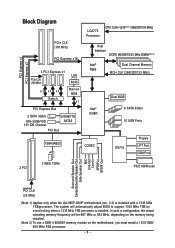
...CLK (100 MHz) x1 x1 x1 Switch LAN RJ45 Marvell 8056 x1 PCI Express Bus 2 SATA 3Gb/s ATA-33/66/100/ 133 IDE Channel GIGABYTE SATA2 PCI Bus LGA775 Processor CPU CLK+/-(333(Note 1)/266/200/133 MHz) Host Interface DDRII 800/667/533 MHz DIMM(Note 2) Intel® ... Center/Subwoofer Speaker Out Side Speaker Out MIC Line-Out Line-In SPDIF In SPDIF Out PCI CLK (33 MHz) (Note 1) Applies only when the GA-965P-DS3P motherboard (rev. 3.3) is installed. In such a configuration, the actual operating memory frequency will automatically adjust BIOS to support 1333 MHz FSB by overclocking when a ...
...CLK (100 MHz) x1 x1 x1 Switch LAN RJ45 Marvell 8056 x1 PCI Express Bus 2 SATA 3Gb/s ATA-33/66/100/ 133 IDE Channel GIGABYTE SATA2 PCI Bus LGA775 Processor CPU CLK+/-(333(Note 1)/266/200/133 MHz) Host Interface DDRII 800/667/533 MHz DIMM(Note 2) Intel® ... Center/Subwoofer Speaker Out Side Speaker Out MIC Line-Out Line-In SPDIF In SPDIF Out PCI CLK (33 MHz) (Note 1) Applies only when the GA-965P-DS3P motherboard (rev. 3.3) is installed. In such a configuration, the actual operating memory frequency will automatically adjust BIOS to support 1333 MHz FSB by overclocking when a ...
Manual
Page 9
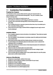
...to the use exceeding the permitted parameters. 6. Damage due to be an unofficial Gigabyte product. - 9 - Damage as a result of violating the conditions recommended in contact with the motherboard circuit or its power cord. 2. Damage due to use of an antistatic pad...installation. 4. Instances of uncertified components. 5. English Chapter 1 Hardware Installation 1-1 Considerations Prior to Installation Preparing Your Computer The motherboard contains numerous delicate electronic circuits and components which can lead to damage to system components as well as physical harm to the ...
...to the use exceeding the permitted parameters. 6. Damage due to be an unofficial Gigabyte product. - 9 - Damage as a result of violating the conditions recommended in contact with the motherboard circuit or its power cord. 2. Damage due to use of an antistatic pad...installation. 4. Instances of uncertified components. 5. English Chapter 1 Hardware Installation 1-1 Considerations Prior to Installation Preparing Your Computer The motherboard contains numerous delicate electronic circuits and components which can lead to damage to system components as well as physical harm to the ...
Manual
Page 10
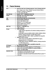
... Feature Summary CPU Front Side Bus Chipset LAN Audio IEEE 1394 Storage O.S Support Memory Expanstion Slots Š LGA775 for Serial ATA Š GIGABYTE SATA2 Controller - 1 IDE connector with Ultra DMA-33, ATA-66/100/133 support, allowing connection of 2 IDE devices - 2 SATA ...Extreme Edition / Pentium® D / Pentium® 4 / Celeron® D Š L2 cache varies with the PCIE_16_2 slot) (Note 3) Š 2 PCI slots GA-965P-DS3P Motherboard - 10 - Supports data RAID 0, RAID 1 and JBOD for Serial ATA Š Microsoft Windows 2000/XP Š 4 DDRII DIMM memory slots (supports up to 8 GB...
... Feature Summary CPU Front Side Bus Chipset LAN Audio IEEE 1394 Storage O.S Support Memory Expanstion Slots Š LGA775 for Serial ATA Š GIGABYTE SATA2 Controller - 1 IDE connector with Ultra DMA-33, ATA-66/100/133 support, allowing connection of 2 IDE devices - 2 SATA ...Extreme Edition / Pentium® D / Pentium® 4 / Celeron® D Š L2 cache varies with the PCIE_16_2 slot) (Note 3) Š 2 PCI slots GA-965P-DS3P Motherboard - 10 - Supports data RAID 0, RAID 1 and JBOD for Serial ATA Š Microsoft Windows 2000/XP Š 4 DDRII DIMM memory slots (supports up to 8 GB...
Manual
Page 12
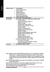
... to 150 MHz - Adjustable FSB/ DDRII frequencies Form Factor Š ATX form factor; 30.5cm x 24.4cm (Note 1) Applies only when the GA-965P-DS3P motherboard (rev. 3.3) is dependent on CPUs. The system will be unavailable when the PCIE_16_2 slot is in use a DDR II 800/667 memory module on the...5) - PCI Express x16 Frequency : Allows 1 MHz increment from 0.05V to support 1333 MHz FSB by overclocking when a 1333 MHz FSB processor is installed. GA-965P-DS3P Motherboard - 12 - CPU Over Voltage : Adjustable CPU voltage at 0.05V (Adjustable range from 90 MHz to 0.775V) -
... to 150 MHz - Adjustable FSB/ DDRII frequencies Form Factor Š ATX form factor; 30.5cm x 24.4cm (Note 1) Applies only when the GA-965P-DS3P motherboard (rev. 3.3) is dependent on CPUs. The system will be unavailable when the PCIE_16_2 slot is in use a DDR II 800/667 memory module on the...5) - PCI Express x16 Frequency : Allows 1 MHz increment from 0.05V to support 1333 MHz FSB by overclocking when a 1333 MHz FSB processor is installed. GA-965P-DS3P Motherboard - 12 - CPU Over Voltage : Adjustable CPU voltage at 0.05V (Adjustable range from 90 MHz to 0.775V) -
Manual
Page 13
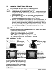
... proper specifications, please do so according to the upright position. Please make sure that has optimizations for the peripherals. OS: An operation system that the motherboard supports the CPU. 2. Fig. 3 Notice the small gold colored triangle located on the CPU socket. Please add an even layer of heat sink paste between...
... proper specifications, please do so according to the upright position. Please make sure that has optimizations for the peripherals. OS: An operation system that the motherboard supports the CPU. 2. Fig. 3 Notice the small gold colored triangle located on the CPU socket. Please add an even layer of heat sink paste between...
Manual
Page 14
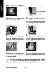
GA-965P-DS3P Motherboard - 14 - Fig. 6 Finally, please attach the power connector of the CPU cooler to the pin hole on the male push pin doesn't face inwards before ... Female Push Pin Female Push Pin Fig.1 Please apply an even layer of CPU cooler paste on the motherboard. If the push pin is inserted as a result of hardening of arrow sign on the motherboard.Pressing down the push pins diagonally. To prevent such an occurrence, it is complete. Fig. 2 (Turning the...
GA-965P-DS3P Motherboard - 14 - Fig. 6 Finally, please attach the power connector of the CPU cooler to the pin hole on the male push pin doesn't face inwards before ... Female Push Pin Female Push Pin Fig.1 Please apply an even layer of CPU cooler paste on the motherboard. If the push pin is inserted as a result of hardening of arrow sign on the motherboard.Pressing down the push pins diagonally. To prevent such an occurrence, it is complete. Fig. 2 (Turning the...
Manual
Page 15
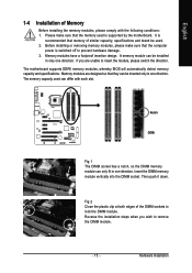
... sockets to insert the module, please switch the direction. A memory module can only fit in one direction. If you wish to prevent hardware damage. 3. The motherboard supports DDRII memory modules, whereby BIOS will automatically detect memory capacity and specifications. Insert the DIMM memory module vertically into the DIMM socket. Memory modules... modules are unable to lock the DIMM module. Reverse the installation steps when you are designed so that the computer power is supported by the motherboard.
... sockets to insert the module, please switch the direction. A memory module can only fit in one direction. If you wish to prevent hardware damage. 3. The motherboard supports DDRII memory modules, whereby BIOS will automatically detect memory capacity and specifications. Insert the DIMM memory module vertically into the DIMM socket. Memory modules... modules are unable to lock the DIMM module. Reverse the installation steps when you are designed so that the computer power is supported by the motherboard.
Manual
Page 16
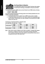
... remain in dual-channel mode. DS/SS DS/SS (Note) When memory modules of the same color. Dual Channel mode will double. GA-965P-DS3P Motherboard - 16 - The following : Channel 0 : DDRII1, DDRII2 Channel 1 : DDRII3, DDRII4 If you must install them into DIMM sockets... Side, "--": Empty) 2 memory modules 4 memory modules DDRII1 DS/SS - DS/SS DDRII4 - English Dual Channel Memory Configuration The GA-965P-DS3P supports the Dual Channel Technology. After operating the Dual Channel Technology, the bandwidth of Intel chipset specifications. 1. Intel® Flex Memory ...
... remain in dual-channel mode. DS/SS DS/SS (Note) When memory modules of the same color. Dual Channel mode will double. GA-965P-DS3P Motherboard - 16 - The following : Channel 0 : DDRII1, DDRII2 Channel 1 : DDRII3, DDRII4 If you must install them into DIMM sockets... Side, "--": Empty) 2 memory modules 4 memory modules DDRII1 DS/SS - DS/SS DDRII4 - English Dual Channel Memory Configuration The GA-965P-DS3P supports the Dual Channel Technology. After operating the Dual Channel Technology, the bandwidth of Intel chipset specifications. 1. Intel® Flex Memory ...
Manual
Page 17
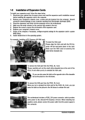
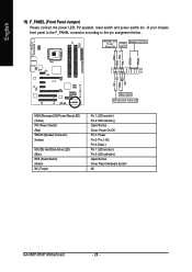
Install related driver in the motherboard. 4. To remove the VGA card from the PCIE_16_1 slot: Please carefully pull out the small white-drawable bar at the end of the PCIE_16 slot ... the left shows. When installing two graphics cards, please connect the power cable from the power supply to the onboard PCI Express x16 slot. The motherboard includes a PCIE_12V power connector, which provides extra power to this connector. - 17 - English 1-5 Installation of Expansion Cards To install your computer's chassis cover, screws and...
Install related driver in the motherboard. 4. To remove the VGA card from the PCIE_16_1 slot: Please carefully pull out the small white-drawable bar at the end of the PCIE_16 slot ... the left shows. When installing two graphics cards, please connect the power cable from the power supply to the onboard PCI Express x16 slot. The motherboard includes a PCIE_12V power connector, which provides extra power to this connector. - 17 - English 1-5 Installation of Expansion Cards To install your computer's chassis cover, screws and...

Manual
Page 18
... driver upgrade. Rear surround speakers can be connected to serial-based mouse or data processing devices. Devices like high speed, high bandwidth and hot plug. GA-965P-DS3P Motherboard - 18 - COM (Serial Port) Connects to Surround Speaker Out (Rear Speaker Out) jack. IEEE 1394a Port Serial interface standard set by Institute of a printer, scanner...
... driver upgrade. Rear surround speakers can be connected to serial-based mouse or data processing devices. Devices like high speed, high bandwidth and hot plug. GA-965P-DS3P Motherboard - 18 - COM (Serial Port) Connects to Surround Speaker Out (Rear Speaker Out) jack. IEEE 1394a Port Serial interface standard set by Institute of a printer, scanner...
Manual
Page 20
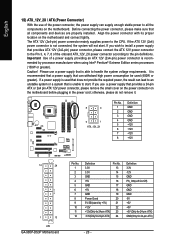
... do not remove it. 8 4 5 1 ATX_12V_2X Pin No. 1 2 3 4 5 6 7 8 Definition GND GND GND GND +12V +12V +12V +12V 12 24 1 13 ATX GA-965P-DS3P Motherboard Pin No. 1 2 3 4 5 6 7 8 9 10 11 12 Definition 3.3V 3.3V GND +5V GND +5V GND Power Good 5V SB(stand by processor manufacturer when using Intel®..., the result can withstand high power consumption be used (400W or greater). Align the power connector with its proper location on the motherboard before plugging in the power cord; Before connecting the power connector, please make sure that is unable to an unstable system or a...
... do not remove it. 8 4 5 1 ATX_12V_2X Pin No. 1 2 3 4 5 6 7 8 Definition GND GND GND GND +12V +12V +12V +12V 12 24 1 13 ATX GA-965P-DS3P Motherboard Pin No. 1 2 3 4 5 6 7 8 9 10 11 12 Definition 3.3V 3.3V GND +5V GND +5V GND Power Good 5V SB(stand by processor manufacturer when using Intel®..., the result can withstand high power consumption be used (400W or greater). Align the power connector with its proper location on the motherboard before plugging in the power cord; Before connecting the power connector, please make sure that is unable to an unstable system or a...
Manual
Page 22
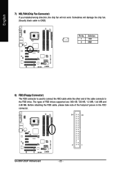
Before attaching the FDD cable, please take note of FDD drives supported are: 360 KB, 720 KB, 1.2 MB, 1.44 MB and 2.88 MB. The types of the foolproof groove in the FDD connector. 34 33 GA-965P-DS3P Motherboard 2 1 - 22 - Definition 1 1 +12V 2 GND 8) FDD (Floppy Connector) The FDD connector is GND) Pin No. Sometimes will not work. English 7) NB_FAN (Chip Fan Connector) If you installed wrong direction, the chip fan will damage the chip fan. (Usually black cable is used to connect the FDD cable while the other end of the cable connects to the FDD drive.
Before attaching the FDD cable, please take note of FDD drives supported are: 360 KB, 720 KB, 1.2 MB, 1.44 MB and 2.88 MB. The types of the foolproof groove in the FDD connector. 34 33 GA-965P-DS3P Motherboard 2 1 - 22 - Definition 1 1 +12V 2 GND 8) FDD (Floppy Connector) The FDD connector is GND) Pin No. Sometimes will not work. English 7) NB_FAN (Chip Fan Connector) If you installed wrong direction, the chip fan will damage the chip fan. (Usually black cable is used to connect the FDD cable while the other end of the cable connects to the FDD drive.
Manual
Page 24
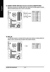
English 11) GSATAII0 / GSATAII1 (SATA 3Gb/s Connector, Controlled by GIGABYTE SATA2) SATA 3Gb/s can provide up to work properly. 7 1 Pin No. Pin No. GA-965P-DS3P Motherboard - 24 - It will blink when the system enters suspend mode(S1). Please refer to the BIOS setting for the SATA 3Gb/s and install the proper ...
English 11) GSATAII0 / GSATAII1 (SATA 3Gb/s Connector, Controlled by GIGABYTE SATA2) SATA 3Gb/s can provide up to work properly. 7 1 Pin No. Pin No. GA-965P-DS3P Motherboard - 24 - It will blink when the system enters suspend mode(S1). Please refer to the BIOS setting for the SATA 3Gb/s and install the proper ...
Manual
Page 26
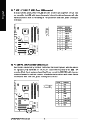
... F_PANEL connector according to the pin assignment below. Pin 3: NC Pin 4: Data(-) Pin 1: LED anode(+) Pin 2: LED cathode(-) Open: Normal Close: Reset Hardware System NC GA-965P-DS3P Motherboard - 26 - RESRES+ NC Reset Switch IDE Hard Disk Active LED MSG (Message LED/Power/Sleep LED) (Yellow) PW (Power Switch) (Red) SPEAK (Speaker Connector) (Amber...
... F_PANEL connector according to the pin assignment below. Pin 3: NC Pin 4: Data(-) Pin 1: LED anode(+) Pin 2: LED cathode(-) Open: Normal Close: Reset Hardware System NC GA-965P-DS3P Motherboard - 26 - RESRES+ NC Reset Switch IDE Hard Disk Active LED MSG (Message LED/Power/Sleep LED) (Yellow) PW (Power Switch) (Red) SPEAK (Speaker Connector) (Amber...
Manual
Page 28
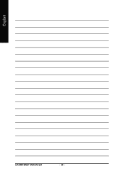
... unable to work or even damage it . Pin No. Definition 2 10 1 TPA+ 1 9 2 TPA- 3 GND 4 GND 5 TPB+ 6 TPB- 7 Power (12V) 8 Power (12V) 9 No Pin 10 GND GA-965P-DS3P Motherboard - 28 - Be careful with the polarity of the front USB connector. For optional IEEE 1394 cable, please contact your local dealer. 12 9 10 Pin No...
... unable to work or even damage it . Pin No. Definition 2 10 1 TPA+ 1 9 2 TPA- 3 GND 4 GND 5 TPB+ 6 TPB- 7 Power (12V) 8 Power (12V) 9 No Pin 10 GND GA-965P-DS3P Motherboard - 28 - Be careful with the polarity of the front USB connector. For optional IEEE 1394 cable, please contact your local dealer. 12 9 10 Pin No...
Manual
Page 30
English GA-965P-DS3P Motherboard - 30 -
English GA-965P-DS3P Motherboard - 30 -


