Manual
Page 4
...GA-965P-DS3P Motherboard Layout 7 Block Diagram ...8 Chapter 1 Hardware Installation 9 1-1 Considerations Prior to Installation 9 1-2 Feature Summary 10 1-3 Installation of the CPU and CPU Cooler 13 1-3-1 Installation of the CPU 13 1-3-2 Installation of the CPU Cooler 14 1-4 Installation of Memory 15 1-5 Installation of Expansion Cards 17 1-6 I/O Back Panel Introduction 18 1-7 Connectors Introduction 19 Chapter 2 BIOS... Setup 31 The Main Menu (For example: BIOS Ver. : F4a 32 2-1 Standard CMOS Features 34 2-2 Advanced BIOS Features 36 2-3 ...
...GA-965P-DS3P Motherboard Layout 7 Block Diagram ...8 Chapter 1 Hardware Installation 9 1-1 Considerations Prior to Installation 9 1-2 Feature Summary 10 1-3 Installation of the CPU and CPU Cooler 13 1-3-1 Installation of the CPU 13 1-3-2 Installation of the CPU Cooler 14 1-4 Installation of Memory 15 1-5 Installation of Expansion Cards 17 1-6 I/O Back Panel Introduction 18 1-7 Connectors Introduction 19 Chapter 2 BIOS... Setup 31 The Main Menu (For example: BIOS Ver. : F4a 32 2-1 Standard CMOS Features 34 2-2 Advanced BIOS Features 36 2-3 ...
Manual
Page 5
Channel Audio Function Introduction 88 4-2 Troubleshooting 93 - 5 - Intel® ICH8R Southbridge 65 B. GIGABYTE SATA2 Controller 76 4-1-5 2- / 4- / 6- / 8- Chapter 3 Drivers Installation 51 3-1 Install Chipset Drivers 51 3-2 SoftwareApplications 52 3-3 Driver CD Information 52 3-4 Hardware Information 53 3-5 Contact Us ...53 Chapter 4 Appendix 55 4-1 Unique Software Utilities 55 4-1-1 EasyTune 5 Introduction 55 4-1-2 Xpress Recovery2 Introduction 56 4-1-3 Flash BIOS Method Introduction 58 4-1-4 Configuring SATA Hard Drive(s 65 A.
Channel Audio Function Introduction 88 4-2 Troubleshooting 93 - 5 - Intel® ICH8R Southbridge 65 B. GIGABYTE SATA2 Controller 76 4-1-5 2- / 4- / 6- / 8- Chapter 3 Drivers Installation 51 3-1 Install Chipset Drivers 51 3-2 SoftwareApplications 52 3-3 Driver CD Information 52 3-4 Hardware Information 53 3-5 Contact Us ...53 Chapter 4 Appendix 55 4-1 Unique Software Utilities 55 4-1-1 EasyTune 5 Introduction 55 4-1-2 Xpress Recovery2 Introduction 56 4-1-3 Flash BIOS Method Introduction 58 4-1-4 Configuring SATA Hard Drive(s 65 A.
Manual
Page 7
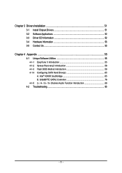
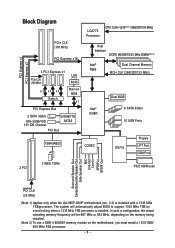
GA-965P-DS3P Motherboard Layout KB_MS COAXIAL OPTICAL ATX_12V_2X LGA775 PWR_FAN PCIE_12V ATX COM LPT 1394 USB GA-965P-DS3P LAN USB AUDIO BATTERY CPU_FAN CLR_CMOS Intel® P965 F_AUDIO PCIE_1 FDD Marvell 8053 PCIE_16_1 NB_FAN DDRII1 DDRII2 DDRII3 DDRII4 PCIE_2 CODEC PCIE_3 CD_IN PCIE_16_2 PCI1 IT8718 PCI2 SPDIF_IN BACKUP MAIN BIOS BIOS CI TSB43AB23 SYS_FAN F1_1394 SATAII0 Intel® ICH8R SATAII4 SATAII1 SATAII2 SATAII5 SATAII3 GIGABYTE SATA2 IDE GSATAII1 GSATAII0 F_USB1 F_USB2 F_USB3 PWR_LED F_PANEL F2_1394 - 7 -
GA-965P-DS3P Motherboard Layout KB_MS COAXIAL OPTICAL ATX_12V_2X LGA775 PWR_FAN PCIE_12V ATX COM LPT 1394 USB GA-965P-DS3P LAN USB AUDIO BATTERY CPU_FAN CLR_CMOS Intel® P965 F_AUDIO PCIE_1 FDD Marvell 8053 PCIE_16_1 NB_FAN DDRII1 DDRII2 DDRII3 DDRII4 PCIE_2 CODEC PCIE_3 CD_IN PCIE_16_2 PCI1 IT8718 PCI2 SPDIF_IN BACKUP MAIN BIOS BIOS CI TSB43AB23 SYS_FAN F1_1394 SATAII0 Intel® ICH8R SATAII4 SATAII1 SATAII2 SATAII5 SATAII3 GIGABYTE SATA2 IDE GSATAII1 GSATAII0 F_USB1 F_USB2 F_USB3 PWR_LED F_PANEL F2_1394 - 7 -
Manual
Page 8
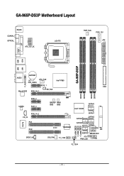
...CLK (100 MHz) x1 x1 x1 Switch LAN RJ45 Marvell 8056 x1 PCI Express Bus 2 SATA 3Gb/s ATA-33/66/100/ 133 IDE Channel GIGABYTE SATA2 PCI Bus LGA775 Processor CPU CLK+/-(333(Note 1)/266/200/133 MHz) Host Interface DDRII 800/667/533 MHz DIMM(Note 2) Intel® ...Line-Out Line-In SPDIF In SPDIF Out PCI CLK (33 MHz) (Note 1) Applies only when the GA-965P-DS3P motherboard (rev. 3.3) is installed. In such a configuration, the actual operating memory frequency will automatically adjust BIOS to support 1333 MHz FSB by overclocking when a 1333 MHz FSB processor is installed with a 1333 MHz...
...CLK (100 MHz) x1 x1 x1 Switch LAN RJ45 Marvell 8056 x1 PCI Express Bus 2 SATA 3Gb/s ATA-33/66/100/ 133 IDE Channel GIGABYTE SATA2 PCI Bus LGA775 Processor CPU CLK+/-(333(Note 1)/266/200/133 MHz) Host Interface DDRII 800/667/533 MHz DIMM(Note 2) Intel® ...Line-Out Line-In SPDIF In SPDIF Out PCI CLK (33 MHz) (Note 1) Applies only when the GA-965P-DS3P motherboard (rev. 3.3) is installed. In such a configuration, the actual operating memory frequency will automatically adjust BIOS to support 1333 MHz FSB by overclocking when a 1333 MHz FSB processor is installed with a 1333 MHz...

Manual
Page 11
... temperature detection Š CPU / System / Power fan speed detection Š CPU warning temperature Š CPU / System / Power fan failure warning Š CPU smart fan control BIOS Š 2 8 Mbit flash ROM Š Use of licensed AWARD...
... temperature detection Š CPU / System / Power fan speed detection Š CPU warning temperature Š CPU / System / Power fan failure warning Š CPU smart fan control BIOS Š 2 8 Mbit flash ROM Š Use of licensed AWARD...
Manual
Page 12
...- PCI Express x16 Frequency : Allows 1 MHz increment from 0.05V to 0.775V) - GA-965P-DS3P Motherboard - 12 - FSB Over Voltage : Adjustable FSB voltage at 0.05V (Adjustable range from 0.025V to 0.35V) Š Over Clock via BIOS (CPU / DDRII / PCI-E / (G)MCH / FSB) - In such a configuration,... Security (OEM revision) Overclocking Š Over Voltage via BIOS (CPU / DDR II / PCI-E) - Adjustable FSB/ DDRII frequencies Form Factor Š ATX form factor; 30.5cm x 24.4cm (Note 1) Applies only when the GA-965P-DS3P motherboard (rev. 3.3) is dependent on the motherboard, you...
...- PCI Express x16 Frequency : Allows 1 MHz increment from 0.05V to 0.775V) - GA-965P-DS3P Motherboard - 12 - FSB Over Voltage : Adjustable FSB voltage at 0.05V (Adjustable range from 0.025V to 0.35V) Š Over Clock via BIOS (CPU / DDRII / PCI-E / (G)MCH / FSB) - In such a configuration,... Security (OEM revision) Overclocking Š Over Voltage via BIOS (CPU / DDR II / PCI-E) - Adjustable FSB/ DDRII frequencies Form Factor Š ATX form factor; 30.5cm x 24.4cm (Note 1) Applies only when the GA-965P-DS3P motherboard (rev. 3.3) is dependent on the motherboard, you...
Manual
Page 13
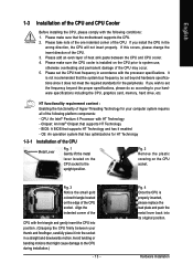
... drive, etc. If this occurs, please change the insert direction of the CPU. It is not recommended that might cause damage to the upright position. BIOS: A BIOS that has optimizations for your thumb and forefinger, carefully place it enabled - OS: An operation system that supports HT Technology and has it into the...
... drive, etc. If this occurs, please change the insert direction of the CPU. It is not recommended that might cause damage to the upright position. BIOS: A BIOS that has optimizations for your thumb and forefinger, carefully place it enabled - OS: An operation system that supports HT Technology and has it into the...
Manual
Page 15
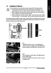
... is recommended that memory of similar capacity, specifications and brand be used can only fit in one direction. The motherboard supports DDRII memory modules, whereby BIOS will automatically detect memory capacity and specifications. Hardware Installation Memory modules have a foolproof insertion design. Reverse the installation steps when you are designed so that...
... is recommended that memory of similar capacity, specifications and brand be used can only fit in one direction. The motherboard supports DDRII memory modules, whereby BIOS will automatically detect memory capacity and specifications. Hardware Installation Memory modules have a foolproof insertion design. Reverse the installation steps when you are designed so that...
Manual
Page 17
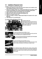
... drawable bar. To remove the VGA card from its power source and read the expansion card's installation manual before installing the expansion card in system BIOS Setup. 8.
... drawable bar. To remove the VGA card from its power source and read the expansion card's installation manual before installing the expansion card in system BIOS Setup. 8.
Manual
Page 23
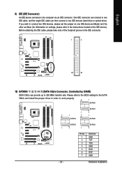
...) SATAII0 / 1 / 2 / 3 / 4 / 5 (SATA 3Gb/s Connector, Controlled by ICH8R) SATA 3Gb/s can then connect to two IDE devices (hard drive or optical drive). Please refer to the BIOS setting for information on settings, please refer to the instructions located on one IDE cable, and the single IDE cable can provide up to work...
...) SATAII0 / 1 / 2 / 3 / 4 / 5 (SATA 3Gb/s Connector, Controlled by ICH8R) SATA 3Gb/s can then connect to two IDE devices (hard drive or optical drive). Please refer to the BIOS setting for information on settings, please refer to the instructions located on one IDE cable, and the single IDE cable can provide up to work...
Manual
Page 24
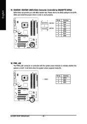
...). English 11) GSATAII0 / GSATAII1 (SATA 3Gb/s Connector, Controlled by GIGABYTE SATA2) SATA 3Gb/s can provide up to indicate whether the system is connected with the system power indicator to 300 MB/s transfer rate. GA-965P-DS3P Motherboard - 24 - Pin No. Please refer to the BIOS setting for the SATA 3Gb/s and install the proper driver...
...). English 11) GSATAII0 / GSATAII1 (SATA 3Gb/s Connector, Controlled by GIGABYTE SATA2) SATA 3Gb/s can provide up to indicate whether the system is connected with the system power indicator to 300 MB/s transfer rate. GA-965P-DS3P Motherboard - 24 - Pin No. Please refer to the BIOS setting for the SATA 3Gb/s and install the proper driver...
Manual
Page 29
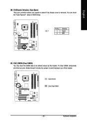
Pin No. Definition 1 1 Signal 2 GND 21) CLR_CMOS (Clear CMOS) You may clear the CMOS data to avoid improper use of this header. Open: Normal Short: Clear CMOS - 29 - Hardware Installation To clear CMOS, temporarily short the two pins. You can check the "Case Opened" status in BIOS Setup. Default doesn't include the jumper to its default values by this header. English 20) CI (Chassis Intrusion, Case Open) This 2-pin connector allows your system to detect if the chassis cover is removed.
Pin No. Definition 1 1 Signal 2 GND 21) CLR_CMOS (Clear CMOS) You may clear the CMOS data to avoid improper use of this header. Open: Normal Short: Clear CMOS - 29 - Hardware Installation To clear CMOS, temporarily short the two pins. You can check the "Case Opened" status in BIOS Setup. Default doesn't include the jumper to its default values by this header. English 20) CI (Chassis Intrusion, Case Open) This 2-pin connector allows your system to detect if the chassis cover is removed.
Manual
Page 31
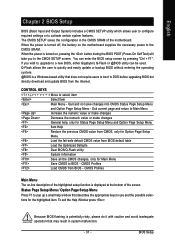
... Input and Output System) includes a CMOS SETUP utility which allows user to configure required settings or to a new BIOS, either Gigabyte's Q-Flash or @BIOS utility can enter the BIOS setup screen by pressing "Ctrl + F1". When the power is potentially risky, please do it with caution and avoid inadequate operation that may result in...
... Input and Output System) includes a CMOS SETUP utility which allows user to configure required settings or to a new BIOS, either Gigabyte's Q-Flash or @BIOS utility can enter the BIOS setup screen by pressing "Ctrl + F1". When the power is potentially risky, please do it with caution and avoid inadequate operation that may result in...
Manual
Page 32
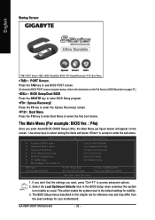
...among the items and press to BIOS F12: Load CMOS from the exact settings for stability. 3. GA-965P-DS3P Motherboard - 32 - Startup Screen: English :POST Screen :BIOS Setup/Dual BIOS :XpressRecovery2 :Boot Menu : POST Screen Press the TAB key to see BIOS POST screen. (To show the BIOS POST screen at system startup, ...refer to the instructions on the Full Screen LOGO Show item on the screen. If you don't find the settings you enter Award BIOS CMOS Setup Utility, the Main Menu (as usual. This action makes the system reset to the default settings for your motherboard. Select ...
...among the items and press to BIOS F12: Load CMOS from the exact settings for stability. 3. GA-965P-DS3P Motherboard - 32 - Startup Screen: English :POST Screen :BIOS Setup/Dual BIOS :XpressRecovery2 :Boot Menu : POST Screen Press the TAB key to see BIOS POST screen. (To show the BIOS POST screen at system startup, ...refer to the instructions on the Full Screen LOGO Show item on the screen. If you don't find the settings you enter Award BIOS CMOS Setup Utility, the Main Menu (as usual. This action makes the system reset to the default settings for your motherboard. Select ...
Manual
Page 33
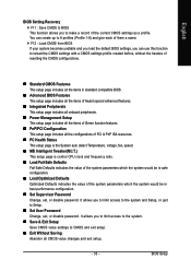
...profile. You can use this function to Setup. „ Set User Password Change, set , or disable password. BIOS Setup English BIOS Setting Recovery F11 : Save CMOS to BIOS This function allows you to limit access to the system. „ Save & Exit Setup Save CMOS value settings ...the hassles of resetting the CMOS configurations. „ Standard CMOS Features This setup page includes all the items in standard compatible BIOS. „ Advanced BIOS Features This setup page includes all the items of Award special enhanced features. „ Integrated Peripherals This setup page includes all ...
...profile. You can use this function to Setup. „ Set User Password Change, set , or disable password. BIOS Setup English BIOS Setting Recovery F11 : Save CMOS to BIOS This function allows you to limit access to the system. „ Save & Exit Setup Save CMOS value settings ...the hassles of resetting the CMOS configurations. „ Standard CMOS Features This setup page includes all the items in standard compatible BIOS. „ Advanced BIOS Features This setup page includes all the items of Award special enhanced features. „ Integrated Peripherals This setup page includes all ...

Manual
Page 34
time clock. You can use one of three methods: • Auto Allows BIOS to Sat, determined by the BIOS and is , , , . The time is 13:00:00. IDE Channel 0/1 Master, Slave IDE HDD Auto-Detection Press "Enter" to automatically detect IDE/SATA devices ...of two methods: • Auto Allows BIOS to select this if no IDE/SATA devices are : CHS/LBA/Large/Auto(default:Auto) IDE Channel 2/3 Master / IDE Channel 4/5 Master, Slave IDE HDD Auto-Detection Press "Enter" to set the access mode for faster system start up . GA-965P-DS3P Motherboard - 34 - is calculated base ...
time clock. You can use one of three methods: • Auto Allows BIOS to Sat, determined by the BIOS and is , , , . The time is 13:00:00. IDE Channel 0/1 Master, Slave IDE HDD Auto-Detection Press "Enter" to automatically detect IDE/SATA devices ...of two methods: • Auto Allows BIOS to select this if no IDE/SATA devices are : CHS/LBA/Large/Auto(default:Auto) IDE Channel 2/3 Master / IDE Channel 4/5 Master, Slave IDE HDD Auto-Detection Press "Enter" to set the access mode for faster system start up . GA-965P-DS3P Motherboard - 34 - is calculated base ...

Manual
Page 35
...capacity. 5.25 inch AT-type high-density drive; 1.2 M byte capacity. 720K, 3.5" (3.5 inch when 3 Mode is 3 mode Floppy Drive. All Errors Whenever the BIOS detects a non-fatal error the system will stop for systems with 640K or more memory installed on the motherboard. it will not stop if an... the types of memory located above 1 MB in the system. Halt on the motherboard, or 640K for a disk error; Extended Memory The BIOS determines how much extended memory is detected during the POST. This is determined by POST (Power On Self Test) of currectly installed hard drive....
...capacity. 5.25 inch AT-type high-density drive; 1.2 M byte capacity. 720K, 3.5" (3.5 inch when 3 Mode is 3 mode Floppy Drive. All Errors Whenever the BIOS detects a non-fatal error the system will stop for systems with 640K or more memory installed on the motherboard. it will not stop if an... the types of memory located above 1 MB in the system. Halt on the motherboard, or 640K for a disk error; Extended Memory The BIOS determines how much extended memory is detected during the POST. This is determined by POST (Power On Self Test) of currectly installed hard drive....
Manual
Page 36
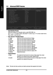
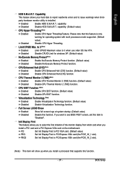
... CMOS Setup Utility-Copyright (C) 1984-2006 Award Software Advanced BIOS Features Hard Disk Boot Priority First Boot Device Second Boot Device Third Boot Device Password Check HDD S.M.A.R.T. Capability CPU Hyper-Threading (Note) Limit CPUID Max. ... your boot device priority by USB-CDROM. USB-HDD Select your boot device priority by USB-HDD. CDROM Select your boot device priority by CDROM. GA-965P-DS3P Motherboard - 36 - Press to Setup page if the correct password is not entered at the prompt. (Note) This item will show up , or to 3 (Note...
... CMOS Setup Utility-Copyright (C) 1984-2006 Award Software Advanced BIOS Features Hard Disk Boot Priority First Boot Device Second Boot Device Third Boot Device Password Check HDD S.M.A.R.T. Capability CPU Hyper-Threading (Note) Limit CPUID Max. ... your boot device priority by USB-CDROM. USB-HDD Select your boot device priority by USB-HDD. CDROM Select your boot device priority by CDROM. GA-965P-DS3P Motherboard - 36 - Press to Setup page if the correct password is not entered at the prompt. (Note) This item will show up , or to 3 (Note...
Manual
Page 37
...Disable CPU Thermal Monitor 2 (TM2) function. Init Display First This feature allows you install a processor that this function. - 37 - Disable HDD S.M.A.R.T. BIOS Setup Disable CPUID Limit for operating system with multi processors mode supported. (Default Disabled value) Disable CPU Hyper Threading. Virtualization Technology (Note) Enabled Enable Virtualization... Show Enabled Disabled Show full screen logo at system startup. (Default value) Disable this item to see BIOS POST screen, set this function. Enabled Disabled Enable HDD S.M.A.R.T. English HDD S.M.A.R.T.
...Disable CPU Thermal Monitor 2 (TM2) function. Init Display First This feature allows you install a processor that this function. - 37 - Disable HDD S.M.A.R.T. BIOS Setup Disable CPUID Limit for operating system with multi processors mode supported. (Default Disabled value) Disable CPU Hyper Threading. Virtualization Technology (Note) Enabled Enable Virtualization... Show Enabled Disabled Show full screen logo at system startup. (Default value) Disable this item to see BIOS POST screen, set this function. Enabled Disabled Enable HDD S.M.A.R.T. English HDD S.M.A.R.T.
Manual
Page 39
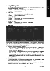
... value) Disable this function. For example, if it shows Pair1-2 Status = Short / Length = 1.6m, it means that a fault or short might occur at Port..... Enabled BIOS will show Normal and the Length fields will scan all USB storage devices. (Default value) Disabled Disable this function. Pair1-2 Status = Normal / Pair3-6 Status = Normal... hub, the Status fields of the attached LAN cable. If no cable problem is detected on the LAN cable connected to the fault or short. BIOS Setup
... value) Disable this function. For example, if it shows Pair1-2 Status = Short / Length = 1.6m, it means that a fault or short might occur at Port..... Enabled BIOS will show Normal and the Length fields will scan all USB storage devices. (Default value) Disabled Disable this function. Pair1-2 Status = Normal / Pair3-6 Status = Normal... hub, the Status fields of the attached LAN cable. If no cable problem is detected on the LAN cable connected to the fault or short. BIOS Setup


