Manual
Page 4
...GA-946GZ-DS3 (rev. 2.0) Motherboard Layout 7 Block Diagram ...8 Chapter 1 Hardware Installation 9 1-1 Considerations Prior to Installation 9 1-2 Feature Summary 10 1-3 Installation of the CPU and CPU Cooler 12 1-3-1 Installation of the CPU 12 1-3-2 Installation of the Cooler 13 1-4 Installation of Memory 14 1-5 Installation of Expansion Cards 16 1-6 I/O Back Panel Introduction 17 1-7 Connectors Introduction 18 Chapter 2 BIOS... Setup 29 The Main Menu (For example: BIOS Ver.: F1a 30 2-1 Standard CMOS Features 32 2-2 Advanced BIOS Features 34 2-3 ...
...GA-946GZ-DS3 (rev. 2.0) Motherboard Layout 7 Block Diagram ...8 Chapter 1 Hardware Installation 9 1-1 Considerations Prior to Installation 9 1-2 Feature Summary 10 1-3 Installation of the CPU and CPU Cooler 12 1-3-1 Installation of the CPU 12 1-3-2 Installation of the Cooler 13 1-4 Installation of Memory 14 1-5 Installation of Expansion Cards 16 1-6 I/O Back Panel Introduction 17 1-7 Connectors Introduction 18 Chapter 2 BIOS... Setup 29 The Main Menu (For example: BIOS Ver.: F1a 30 2-1 Standard CMOS Features 32 2-2 Advanced BIOS Features 34 2-3 ...

Manual
Page 5
Channel Audio Function Introduction 67 4-2 Troubleshooting 72 - 5 - Chapter 3 Install Drivers 51 3-1 Install Chipset Drivers 51 3-2 SoftwareApplications 52 3-3 Driver CD Information 52 3-4 Hardware Information 53 3-5 Contact Us ...53 Chapter 4 Appendix 55 4-1 Unique Software Utilities 55 4-1-1 EasyTune 5 Introduction 55 4-1-2 Xpress Recovery2 Introduction 56 4-1-3 Flash BIOS Method Introduction 58 4-1-4 2- / 4- / 6- / 8-
Channel Audio Function Introduction 67 4-2 Troubleshooting 72 - 5 - Chapter 3 Install Drivers 51 3-1 Install Chipset Drivers 51 3-2 SoftwareApplications 52 3-3 Driver CD Information 52 3-4 Hardware Information 53 3-5 Contact Us ...53 Chapter 4 Appendix 55 4-1 Unique Software Utilities 55 4-1-1 EasyTune 5 Introduction 55 4-1-2 Xpress Recovery2 Introduction 56 4-1-3 Flash BIOS Method Introduction 58 4-1-4 2- / 4- / 6- / 8-
Manual
Page 7
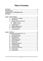
REV: 2.0 IT8718 GA-946GZ-DS3 (rev. 2.0) Motherboard Layout KB_MS ATX_12V LGA775 CPU_FAN COMA LPT VGA USB USB_LAN AUDIO1 AUDIO2 F_AUDIO NB_FAN RTL 8111B Intel® 946GZ PCIE_3 PCIE_16 GA-946GZ-DS3 PWR_FAN ATX DDRII1 DDRII2 DDRII3 DDRII4 CODEC PCIE_1 PCIE_2 CI CD_IN FDD SPDIF_IO CLR_CMOS BATTERY Intel® ICH7 SYS _FAN PCI1 PCI2 BIOS SATAII0 SATAII2 SATAII1 SATAII3 PCI3 IDE1 F_USB2 F_PANEL F_USB1 PWR_LED - 7 -
REV: 2.0 IT8718 GA-946GZ-DS3 (rev. 2.0) Motherboard Layout KB_MS ATX_12V LGA775 CPU_FAN COMA LPT VGA USB USB_LAN AUDIO1 AUDIO2 F_AUDIO NB_FAN RTL 8111B Intel® 946GZ PCIE_3 PCIE_16 GA-946GZ-DS3 PWR_FAN ATX DDRII1 DDRII2 DDRII3 DDRII4 CODEC PCIE_1 PCIE_2 CI CD_IN FDD SPDIF_IO CLR_CMOS BATTERY Intel® ICH7 SYS _FAN PCI1 PCI2 BIOS SATAII0 SATAII2 SATAII1 SATAII3 PCI3 IDE1 F_USB2 F_PANEL F_USB1 PWR_LED - 7 -

Manual
Page 8
... Express Bus x1 x1 x1 PCIe CLK (100 MHz) 3 PCI Express x1 PCI Bus Host Interface Intel® 946GZ DDRII 667(Note)/533 MHz DIMM Dual Channel Memory GMCH CLK (266/200/133 MHz) BIOS ATA33/66/100 IDE Channel Intel® ICH7 4 SATA 3Gb/s Floppy IT8718 LPT Port COM Port 3 PCI...
... Express Bus x1 x1 x1 PCIe CLK (100 MHz) 3 PCI Express x1 PCI Bus Host Interface Intel® 946GZ DDRII 667(Note)/533 MHz DIMM Dual Channel Memory GMCH CLK (266/200/133 MHz) BIOS ATA33/66/100 IDE Channel Intel® ICH7 4 SATA 3Gb/s Floppy IT8718 LPT Port COM Port 3 PCI...

Manual
Page 11
... temperature Š CPU / System / Power fan failure warning Š Supports CPU Smart Fan function BIOS Š 1 4 Mbit flash ROM Š Use of licensed AWARD BIOS Additional Features Š Supports @BIOS Š Supports Download Center Š Supports Q-Flash Š Supports EasyTune(Note 4) Š Supports... Xpress Install Š Supports Xpress Recovery2 Š Supports Xpress BIOS Rescue Bundle Software Š Norton Internet Security (OEM version) Form Factor Š ATX form factor; 30.5cm x 21.0cm (...
... temperature Š CPU / System / Power fan failure warning Š Supports CPU Smart Fan function BIOS Š 1 4 Mbit flash ROM Š Use of licensed AWARD BIOS Additional Features Š Supports @BIOS Š Supports Download Center Š Supports Q-Flash Š Supports EasyTune(Note 4) Š Supports... Xpress Install Š Supports Xpress Recovery2 Š Supports Xpress BIOS Rescue Bundle Software Š Norton Internet Security (OEM version) Form Factor Š ATX form factor; 30.5cm x 21.0cm (...

Manual
Page 12
... lever located on the CPU prior to the upright position. Please set beyond the proper specifications, please do so according to the CPU during installation.) GA-946GZ-DS3 (rev. 2.0) Motherboard - 12 - CPU: An Intel® Pentium 4 Processor with the following platform components: - Fig. 2 Remove the plastic covering on the edge ... of the CPU. 3. If you install the CPU in accordance with the triangle and gently insert the CPU into its original position. BIOS: A BIOS that supports HT Technology - Fig. 3 Notice the small gold colored triangle located on the CPU socket.
... lever located on the CPU prior to the upright position. Please set beyond the proper specifications, please do so according to the CPU during installation.) GA-946GZ-DS3 (rev. 2.0) Motherboard - 12 - CPU: An Intel® Pentium 4 Processor with the following platform components: - Fig. 2 Remove the plastic covering on the edge ... of the CPU. 3. If you install the CPU in accordance with the triangle and gently insert the CPU into its original position. BIOS: A BIOS that supports HT Technology - Fig. 3 Notice the small gold colored triangle located on the CPU socket.

Manual
Page 14
...have a foolproof insertion design. If you wish to prevent hardware damage. 3. The motherboard supports DDRII memory modules, whereby BIOS will automatically detect memory capacity and specifications. Notch DDRII Fig.1 The DIMM socket has a notch, so the DIMM ...the direction. It is recommended that the computer power is supported by the motherboard. Insert the DIMM memory module vertically into the DIMM socket. GA-946GZ-DS3 (rev. 2.0) Motherboard - 14 - A memory module can differ with the following conditions: 1. Memory modules are unable to lock the DIMM ...
...have a foolproof insertion design. If you wish to prevent hardware damage. 3. The motherboard supports DDRII memory modules, whereby BIOS will automatically detect memory capacity and specifications. Notch DDRII Fig.1 The DIMM socket has a notch, so the DIMM ...the direction. It is recommended that the computer power is supported by the motherboard. Insert the DIMM memory module vertically into the DIMM socket. GA-946GZ-DS3 (rev. 2.0) Motherboard - 14 - A memory module can differ with the following conditions: 1. Memory modules are unable to lock the DIMM ...
Manual
Page 16
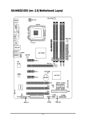
Be sure the metal contacts on the computer, if necessary, setup BIOS utility of expansion card from BIOS. 8. GA-946GZ-DS3 (rev. 2.0) Motherboard - 16 - Remove your computer's chassis cover. 7. Press the expansion card firmly into the computer. 2. Replace your computer's chassis cover, screws and slot bracket ...
Be sure the metal contacts on the computer, if necessary, setup BIOS utility of expansion card from BIOS. 8. GA-946GZ-DS3 (rev. 2.0) Motherboard - 16 - Remove your computer's chassis cover. 7. Press the expansion card firmly into the computer. 2. Replace your computer's chassis cover, screws and slot bracket ...
Manual
Page 22
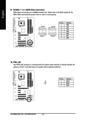
Please refer to the BIOS setting for the SATA 3Gb/s and install the proper driver in order to indicate whether the system is on/off. Pin No. It will blink ... Pin No. 1 2 3 4 5 6 7 Definition GND TXP TXN GND RXN RXP GND 10) PWR_LED The PWR_LED connector is connected with the system power indicator to work properly. GA-946GZ-DS3 (rev. 2.0) Motherboard - 22 - Definition 1 MPD+ 1 2 MPD- 3 MPD- English 9) SATAII0 / 1 / 2 / 3 (SATA 3Gb/s Connectors) SATA 3Gb/s can provide up to 300MB/s transfer rate...
Please refer to the BIOS setting for the SATA 3Gb/s and install the proper driver in order to indicate whether the system is on/off. Pin No. It will blink ... Pin No. 1 2 3 4 5 6 7 Definition GND TXP TXN GND RXN RXP GND 10) PWR_LED The PWR_LED connector is connected with the system power indicator to work properly. GA-946GZ-DS3 (rev. 2.0) Motherboard - 22 - Definition 1 MPD+ 1 2 MPD- 3 MPD- English 9) SATAII0 / 1 / 2 / 3 (SATA 3Gb/s Connectors) SATA 3Gb/s can provide up to 300MB/s transfer rate...
Manual
Page 26
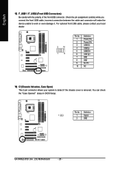
.... English 15) F_USB1 / F_USB2 (Front USB Connectors) Be careful with the polarity of the front USB connector. You can check the "Case Opened" status in BIOS Setup. Pin No. For optional front USB cable, please contact your local dealer. 2 10 1 9 Pin No. 1 2 3 4 5 6 7 8 9 10 Definition Power (5V) Power (5V) USB DXUSB DyUSB... GND No Pin NC 16) CI (Chassis Intrusion, Case Open) This 2-pin connector allows your system to work or even damage it. Definition 1 1 Signal 2 GND GA-946GZ-DS3 (rev. 2.0) Motherboard - 26 -
.... English 15) F_USB1 / F_USB2 (Front USB Connectors) Be careful with the polarity of the front USB connector. You can check the "Case Opened" status in BIOS Setup. Pin No. For optional front USB cable, please contact your local dealer. 2 10 1 9 Pin No. 1 2 3 4 5 6 7 8 9 10 Definition Power (5V) Power (5V) USB DXUSB DyUSB... GND No Pin NC 16) CI (Chassis Intrusion, Case Open) This 2-pin connector allows your system to work or even damage it. Definition 1 1 Signal 2 GND GA-946GZ-DS3 (rev. 2.0) Motherboard - 26 -

Manual
Page 29
... description of the highlighted setup function is displayed at the bottom of the motherboard. BIOS Setup The CMOS SETUP saves the configuration in system malfunction. - 29 - If you to a new BIOS, either Gigabyte's Q-Flash or @BIOS utility can enter the BIOS setup screen by pressing "Ctrl + F1". Quit and not save changes into CMOS Status...
... description of the highlighted setup function is displayed at the bottom of the motherboard. BIOS Setup The CMOS SETUP saves the configuration in system malfunction. - 29 - If you to a new BIOS, either Gigabyte's Q-Flash or @BIOS utility can enter the BIOS setup screen by pressing "Ctrl + F1". Quit and not save changes into CMOS Status...

Manual
Page 30
...Ctrl+F1" to accept or enter the sub-menu. CMOS Setup Utility-Copyright (C) 1984-2006 Award Software ` Standard CMOS Features ` Advanced BIOS Features ` Integrated Peripherals ` Power Management Setup ` PnP/PCI Configurations ` PC Health Status ` MB Intelligent Tweaker(M.I.T.) Load Fail-Safe Defaults ...: English :POST Screen :BIOS Setup/Q-Flash :XpressRecovery2 :Boot Menu : POST Screen Press the TAB key to see BIOS POST screen. (To show the BIOS POST screen at system startup, refer to the instructions on the Full Screen LOGO Show item on the screen. GA-946GZ-DS3 (rev. 2.0) Motherboard -...
...Ctrl+F1" to accept or enter the sub-menu. CMOS Setup Utility-Copyright (C) 1984-2006 Award Software ` Standard CMOS Features ` Advanced BIOS Features ` Integrated Peripherals ` Power Management Setup ` PnP/PCI Configurations ` PC Health Status ` MB Intelligent Tweaker(M.I.T.) Load Fail-Safe Defaults ...: English :POST Screen :BIOS Setup/Q-Flash :XpressRecovery2 :Boot Menu : POST Screen Press the TAB key to see BIOS POST screen. (To show the BIOS POST screen at system startup, refer to the instructions on the Full Screen LOGO Show item on the screen. GA-946GZ-DS3 (rev. 2.0) Motherboard -...

Manual
Page 31
...the system. „ Save & Exit Setup Save CMOS value settings to Setup. „ Set User Password Change, set , or disable password. BIOS Setup It allows you to limit access to the system and Setup, or just to CMOS and exit setup. „ Exit Without Saving Abandon ... value changes and exit setup. - 31 - English „ Standard CMOS Features This setup page includes all the items in standard compatible BIOS. „ Advanced BIOS Features This setup page includes all the items of Award special enhanced features. „ Integrated Peripherals This setup page includes all onboard peripherals....
...the system. „ Save & Exit Setup Save CMOS value settings to Setup. „ Set User Password Change, set , or disable password. BIOS Setup It allows you to limit access to the system and Setup, or just to CMOS and exit setup. „ Exit Without Saving Abandon ... value changes and exit setup. - 31 - English „ Standard CMOS Features This setup page includes all the items in standard compatible BIOS. „ Advanced BIOS Features This setup page includes all the items of Award special enhanced features. „ Integrated Peripherals This setup page includes all onboard peripherals....
Manual
Page 32
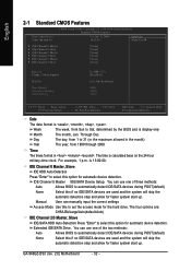
...military-time clock. You can use one of three methods: Auto Allows BIOS to select this if no IDE/SATA devices are used and the system will skip the automatic detection step and allow for automatic device detection. GA-946GZ-DS3 (rev. 2.0) Motherboard - 32 - IDE Channel 0 Master IDE/SATA... Device Setup. Manual User can use one of the two methods: Auto None Allows BIOS to set the access mode for the hard drive. The day,...
...military-time clock. You can use one of three methods: Auto Allows BIOS to select this if no IDE/SATA devices are used and the system will skip the automatic detection step and allow for automatic device detection. GA-946GZ-DS3 (rev. 2.0) Motherboard - 32 - IDE Channel 0 Master IDE/SATA... Device Setup. Manual User can use one of the two methods: Auto None Allows BIOS to set the access mode for the hard drive. The day,...

Manual
Page 33
... not stop for Japan Area) Disabled Normal Floppy Drive. (Default value) Drive A Drive A is 3 mode Floppy Drive. Extended Memory The BIOS determines how much extended memory is Enabled). 720K, 3.5" 1.44M, 3.5" 3.5 inch double-sided drive; 720K byte capacity 3.5 inch double-sided drive...; 1.44M byte capacity. 2.88M, 3.5" 3.5 inch double-sided drive; 2.88M byte capacity. BIOS Setup Cylinder Number of cylinders Head Precomp Number of heads Write precomp Landing Zone Sector Landing zone Number of sectors Drive A The category identifies...
... not stop for Japan Area) Disabled Normal Floppy Drive. (Default value) Drive A Drive A is 3 mode Floppy Drive. Extended Memory The BIOS determines how much extended memory is Enabled). 720K, 3.5" 1.44M, 3.5" 3.5 inch double-sided drive; 720K byte capacity 3.5 inch double-sided drive...; 1.44M byte capacity. 2.88M, 3.5" 3.5 inch double-sided drive; 2.88M byte capacity. BIOS Setup Cylinder Number of cylinders Head Precomp Number of heads Write precomp Landing Zone Sector Landing zone Number of sectors Drive A The category identifies...

Manual
Page 34
...Select your boot device priority by ZIP. Select your boot device priority by USB-ZIP. English 2-2 Advanced BIOS Features CMOS Setup Utility-Copyright (C) 1984-2006 Award Software Advanced BIOS Features ` Hard Disk Boot Priority First Boot Device Second Boot Device Third Boot Device Password Check HDD S.M.A.R.T.... priority by CDROM. Password Check Setup The system will boot but will not access to exit this function. Disable this menu. GA-946GZ-DS3 (rev. 2.0) Motherboard - 34 - Press to Setup page if the correct password is not entered at the prompt. LAN ...
...Select your boot device priority by ZIP. Select your boot device priority by USB-ZIP. English 2-2 Advanced BIOS Features CMOS Setup Utility-Copyright (C) 1984-2006 Award Software Advanced BIOS Features ` Hard Disk Boot Priority First Boot Device Second Boot Device Third Boot Device Password Check HDD S.M.A.R.T.... priority by CDROM. Password Check Setup The system will boot but will not access to exit this function. Disable this menu. GA-946GZ-DS3 (rev. 2.0) Motherboard - 34 - Press to Setup page if the correct password is not entered at the prompt. LAN ...
Manual
Page 35
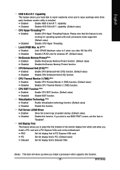
... issue warnings when third- PCI Set Init display first to PCI. (Default value) Onboard Set Init display first to see BIOS POST screen, set this function. English HDD S.M.A.R.T. Capability This feature allows your hard disk to report read/write errors and ...Thermal Monitor 2 (TM2) function. CPU EIST Function (Note) Enabled Enable CPU EIST function. (Default value) Disabled Disable EIST function. capability. BIOS Setup Limit CPUID Max. capability. (Default value) CPU Hyper-Threading (Note) Enabled Enable CPU Hyper Threading Feature. Init Display First This feature ...
... issue warnings when third- PCI Set Init display first to PCI. (Default value) Onboard Set Init display first to see BIOS POST screen, set this function. English HDD S.M.A.R.T. Capability This feature allows your hard disk to report read/write errors and ...Thermal Monitor 2 (TM2) function. CPU EIST Function (Note) Enabled Enable CPU EIST function. (Default value) Disabled Disable EIST function. capability. BIOS Setup Limit CPUID Max. capability. (Default value) CPU Hyper-Threading (Note) Enabled Enable CPU Hyper Threading Feature. Init Display First This feature ...

Manual
Page 36
... On-Chip SATA mode to Non-Combined, SATA will be simulated to 1MB. 8MB Set on the motherboard; 2 for SATA and the other for PATA. GA-946GZ-DS3 (rev. 2.0) Motherboard - 36 - On-Chip Frame Buffer Size 1MB Set on-chip frame buffer size to PATA mode. PATA devices will be ignored. Enable ... On-Chip Primary PCI IDE On-Chip SATA Mode x PATA IDE Set to SATA Port 0/2 Set to SATA Port 1/3 Set to Always Enable. Auto BIOS will auto detect. (Default value) Combined Set On-Chip SATA mode to Combined, you wish to set up to 6 HDDs to activate the onboard VGA...
... On-Chip SATA mode to Non-Combined, SATA will be simulated to 1MB. 8MB Set on the motherboard; 2 for SATA and the other for PATA. GA-946GZ-DS3 (rev. 2.0) Motherboard - 36 - On-Chip Frame Buffer Size 1MB Set on-chip frame buffer size to PATA mode. PATA devices will be ignored. Enable ... On-Chip Primary PCI IDE On-Chip SATA Mode x PATA IDE Set to SATA Port 0/2 Set to SATA Port 1/3 Set to Always Enable. Auto BIOS will auto detect. (Default value) Combined Set On-Chip SATA mode to Combined, you wish to set up to 6 HDDs to activate the onboard VGA...
Manual
Page 37
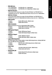
... (Default value) Disable Azalia audio function. Disabled Disable USB Keyboard Support. (Default value) USB Mouse Support Enabled Enable USB Mouse Support. BIOS Setup If PATA IDE were set to Ch. 1 Master/Slave,this function if you are not using onboard USB 2.0 feature. Disabled Disable...this function. - 37 - SATA Port 1/3 Set to ". USB Controller Enabled Disabled Enable USB Controller. (Default value) Disable USB Controller. Enabled BIOS will auto make by the setting "On-Chip SATA Mode" and "PATA IDE Set to This value will scan all USB storage devices. (Default...
... (Default value) Disable Azalia audio function. Disabled Disable USB Keyboard Support. (Default value) USB Mouse Support Enabled Enable USB Mouse Support. BIOS Setup If PATA IDE were set to Ch. 1 Master/Slave,this function if you are not using onboard USB 2.0 feature. Disabled Disable...this function. - 37 - SATA Port 1/3 Set to ". USB Controller Enabled Disabled Enable USB Controller. (Default value) Disable USB Controller. Enabled BIOS will auto make by the setting "On-Chip SATA Mode" and "PATA IDE Set to This value will scan all USB storage devices. (Default...

Manual
Page 39
... as Standard Parallel Port. (Default value) EPP Using Parallel port as Extended Capabilities Port. ECP+EPP Using Parallel port as ECP & EPP mode. - 39 - BIOS Setup BIOS will automatically setup the port 1 address. Enabled Disabled Enable this function. (Default value) Onboard Serial Port 1 Disabled 3F8/IRQ4 Disable onboard Serial port 1. English OnBoard...
... as Standard Parallel Port. (Default value) EPP Using Parallel port as Extended Capabilities Port. ECP+EPP Using Parallel port as ECP & EPP mode. - 39 - BIOS Setup BIOS will automatically setup the port 1 address. Enabled Disabled Enable this function. (Default value) Onboard Serial Port 1 Disabled 3F8/IRQ4 Disable onboard Serial port 1. English OnBoard...


