Manual
Page 6
Item Checklist IDE Cable x 1, FDD Cable x 1 SATA 3Gb/s Cable x 2 I/O Shield * The items listed above are for reference only, and are subject to change without notice. Optional Accessories Š 2 Ports USB 2.0 Cable (Part Number: 12CR1-1UB030-51/R) Š 4 Ports USB 2.0 Cable (Part Number: 12CR1-1UB030-21/R) Š SPDIF In and Out Cable (Part Number: 12CR1-1SPINO-11/R) Š e-SATA Cable (Part Number: 12CF1-3SATPW-11R) - 6 -
Item Checklist IDE Cable x 1, FDD Cable x 1 SATA 3Gb/s Cable x 2 I/O Shield * The items listed above are for reference only, and are subject to change without notice. Optional Accessories Š 2 Ports USB 2.0 Cable (Part Number: 12CR1-1UB030-51/R) Š 4 Ports USB 2.0 Cable (Part Number: 12CR1-1UB030-21/R) Š SPDIF In and Out Cable (Part Number: 12CR1-1SPINO-11/R) Š e-SATA Cable (Part Number: 12CF1-3SATPW-11R) - 6 -
Manual
Page 9
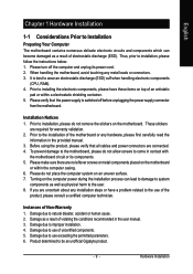
... result of the motherboard or any hardware, please first carefully read the information in the provided manual. 3. Damage due to be an unofficial Gigabyte product. - 9 - Damage due to installation, please follow the instructions below: 1. Please make sure there are connected. 4. Thus, prior... to use of Non-Warranty 1. Please verify that all cables and power connectors are no leftover screws or metal components placed on the motherboard. If you are required for warranty validation. 2. ...
... result of the motherboard or any hardware, please first carefully read the information in the provided manual. 3. Damage due to be an unofficial Gigabyte product. - 9 - Damage due to installation, please follow the instructions below: 1. Please make sure there are connected. 4. Thus, prior... to use of Non-Warranty 1. Please verify that all cables and power connectors are no leftover screws or metal components placed on the motherboard. If you are required for warranty validation. 2. ...
Manual
Page 10
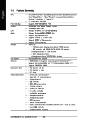
...; 4 / Celeron® D Š L2 cache varies with CPU Front Side Bus Š Supports 1066/800/533 MHz FSB Chipset Northbridge: Intel® 946GZ Express Chipset Š Southbridge: Intel® ICH7 LAN Š Onboard RTL8111B chip (10/100/1000Mbit) Audio Š Onboard Realtek ALC888 CODEC chip Š ...Š 1 front audio connector Š 1 CD In connector Š 1 S/PDIF In/Out connector Š 2 USB 2.0/1.1 connectors for additional 4 USB 2.0/1.1 ports by cables Š 1 power LED connector Š 1 Chassis Intrusion connector GA-946GZ-DS3 (rev. 2.0) Motherboard - 10 -
...; 4 / Celeron® D Š L2 cache varies with CPU Front Side Bus Š Supports 1066/800/533 MHz FSB Chipset Northbridge: Intel® 946GZ Express Chipset Š Southbridge: Intel® ICH7 LAN Š Onboard RTL8111B chip (10/100/1000Mbit) Audio Š Onboard Realtek ALC888 CODEC chip Š ...Š 1 front audio connector Š 1 CD In connector Š 1 S/PDIF In/Out connector Š 2 USB 2.0/1.1 connectors for additional 4 USB 2.0/1.1 ports by cables Š 1 power LED connector Š 1 Chassis Intrusion connector GA-946GZ-DS3 (rev. 2.0) Motherboard - 10 -
Manual
Page 20
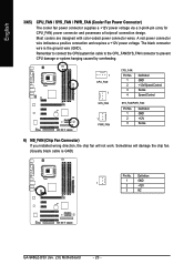
... connector wire is GND) Pin No. Sometimes will not work. Definition 1 GND 1 2 +12V 3 NC GA-946GZ-DS3 (rev. 2.0) Motherboard - 20 - Remember to connect the CPU/system fan cable to the CPU_FAN/SYS_FAN connector to prevent CPU damage or system hanging caused by overheating. 1 CPU_FAN 1 SYS_FAN 1... GND +12V Sense 6) NB_FAN (Chip Fan Connector) If you installed wrong direction, the chip fan will damage the chip fan. (Usually black cable is the ground wire (GND). A red power connector wire indicates a positive connection and requires a +12V power voltage. Most coolers are designed...
... connector wire is GND) Pin No. Sometimes will not work. Definition 1 GND 1 2 +12V 3 NC GA-946GZ-DS3 (rev. 2.0) Motherboard - 20 - Remember to connect the CPU/system fan cable to the CPU_FAN/SYS_FAN connector to prevent CPU damage or system hanging caused by overheating. 1 CPU_FAN 1 SYS_FAN 1... GND +12V Sense 6) NB_FAN (Chip Fan Connector) If you installed wrong direction, the chip fan will damage the chip fan. (Usually black cable is the ground wire (GND). A red power connector wire indicates a positive connection and requires a +12V power voltage. Most coolers are designed...
Manual
Page 21
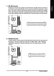
Hardware Installation If you wish to the FDD drive. Before attaching the FDD cable, please take note of the cable connects to connect two IDE devices, please set the jumper on the IDE device). Before attaching the IDE cable, please take note of FDD drives supported are: 360KB, 720KB, 1.2MB... 8) FDD (FDD Connector) The FDD connector is used to connect the FDD cable while the other as Slave (for information on settings, please refer to the instructions located on one IDE cable, and the single IDE cable can then connect to the computer via an IDE connector. English 7) IDE1 (...
Hardware Installation If you wish to the FDD drive. Before attaching the FDD cable, please take note of the cable connects to connect two IDE devices, please set the jumper on the IDE device). Before attaching the IDE cable, please take note of FDD drives supported are: 360KB, 720KB, 1.2MB... 8) FDD (FDD Connector) The FDD connector is used to connect the FDD cable while the other as Slave (for information on settings, please refer to the instructions located on one IDE cable, and the single IDE cable can then connect to the computer via an IDE connector. English 7) IDE1 (...
Manual
Page 25
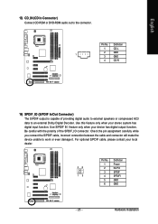
... your stereo system has digital input function. Check the pin assignment carefully while you connect the S/PDIF cable, incorrect connection between the cable and connector will make the device unable to the connector. For optional S/PDIF cable, please contact your local dealer. 26 15 Pin No. 1 2 3 4 5 6 Definition Power No Pin SPDIF SPDIFI GND...
... your stereo system has digital input function. Check the pin assignment carefully while you connect the S/PDIF cable, incorrect connection between the cable and connector will make the device unable to the connector. For optional S/PDIF cable, please contact your local dealer. 26 15 Pin No. 1 2 3 4 5 6 Definition Power No Pin SPDIF SPDIFI GND...
Manual
Page 26
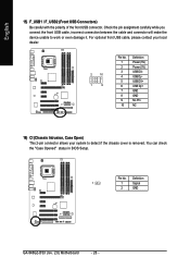
For optional front USB cable, please contact your local dealer. 2 10 1 9 Pin No. 1 2 3 4 5 6 7 8 9 10 Definition Power (5V) Power (5V) USB DXUSB DyUSB DX+ USB Dy+ GND GND No Pin NC ... it. Pin No. You can check the "Case Opened" status in BIOS Setup. Definition 1 1 Signal 2 GND GA-946GZ-DS3 (rev. 2.0) Motherboard - 26 - Check the pin assignment carefully while you connect the front USB cable, incorrect connection between the cable and connector will make the device unable to detect if the chassis cover is removed. English...
For optional front USB cable, please contact your local dealer. 2 10 1 9 Pin No. 1 2 3 4 5 6 7 8 9 10 Definition Power (5V) Power (5V) USB DXUSB DyUSB DX+ USB Dy+ GND GND No Pin NC ... it. Pin No. You can check the "Case Opened" status in BIOS Setup. Definition 1 1 Signal 2 GND GA-946GZ-DS3 (rev. 2.0) Motherboard - 26 - Check the pin assignment carefully while you connect the front USB cable, incorrect connection between the cable and connector will make the device unable to detect if the chassis cover is removed. English...
Manual
Page 38
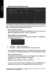
...status of 10/100Mbps in Windows mode or when the LAN Boot ROM is detected on a specified pair of the attached LAN cable. Pair1-2 Status = Open Pair3-6 Status = Open Pair4-5 Status = Open Pair7-8 Status = Open / Length = / Length..., the following information for diagnosing your LAN cable: When No LAN Cable Is Attached... When LAN Cable Is Functioning Normally... If a cable problem occurs on the LAN cable connected to the motherboard, the Status fields ...and Pair 7-8 are not used in the figure above. If no cable problem is activated. GA-946GZ-DS3 (rev. 2.0) Motherboard - 38 -
...status of 10/100Mbps in Windows mode or when the LAN Boot ROM is detected on a specified pair of the attached LAN cable. Pair1-2 Status = Open Pair3-6 Status = Open Pair4-5 Status = Open Pair7-8 Status = Open / Length = / Length..., the following information for diagnosing your LAN cable: When No LAN Cable Is Attached... When LAN Cable Is Functioning Normally... If a cable problem occurs on the LAN cable connected to the motherboard, the Status fields ...and Pair 7-8 are not used in the figure above. If no cable problem is activated. GA-946GZ-DS3 (rev. 2.0) Motherboard - 38 -
Manual
Page 43
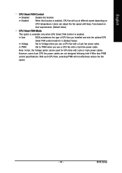
... used for it. (Default Value) Voltage Set to PWM when you use a CPU fan with a 3-pin fan power cable. However, some 4-pin CPU fan power cables are not designed following Intel 4-Wire fans PWM control specifications. Auto BIOS autodetects the type of CPU fan you installed and sets...- 43 - PWM Set to Voltage when you use a CPU fan with a 4-pin fan power cable. Note: In fact, the Voltage option can adjust the fan speed with 3-pin or 4-pin power cables. BIOS Setup English CPU Smart FAN Control Disabled Disable this function is enabled. Enabled When this function....
... used for it. (Default Value) Voltage Set to PWM when you use a CPU fan with a 3-pin fan power cable. However, some 4-pin CPU fan power cables are not designed following Intel 4-Wire fans PWM control specifications. Auto BIOS autodetects the type of CPU fan you installed and sets...- 43 - PWM Set to Voltage when you use a CPU fan with a 4-pin fan power cable. Note: In fact, the Voltage option can adjust the fan speed with 3-pin or 4-pin power cables. BIOS Setup English CPU Smart FAN Control Disabled Disable this function is enabled. Enabled When this function....


