Manual
Page 4
... GA-946GZ-DS3 (rev. 2.0) Motherboard Layout 7 Block Diagram ...8 Chapter 1 Hardware Installation 9 1-1 Considerations Prior to Installation 9 1-2 Feature Summary 10 1-3 Installation of the CPU and CPU Cooler 12 1-3-1 Installation of the CPU 12 1-3-2 Installation of the Cooler 13 1-4 Installation of Memory 14 1-5 Installation of Expansion Cards 16 1-6 I/O Back Panel Introduction 17 1-7 Connectors Introduction 18 Chapter 2 BIOS Setup 29 The Main Menu (For example: BIOS Ver.: F1a 30 2-1 Standard CMOS Features 32 2-2 Advanced BIOS Features 34 2-3 IntegratedPeripherals 36 2-4 Power...
... GA-946GZ-DS3 (rev. 2.0) Motherboard Layout 7 Block Diagram ...8 Chapter 1 Hardware Installation 9 1-1 Considerations Prior to Installation 9 1-2 Feature Summary 10 1-3 Installation of the CPU and CPU Cooler 12 1-3-1 Installation of the CPU 12 1-3-2 Installation of the Cooler 13 1-4 Installation of Memory 14 1-5 Installation of Expansion Cards 16 1-6 I/O Back Panel Introduction 17 1-7 Connectors Introduction 18 Chapter 2 BIOS Setup 29 The Main Menu (For example: BIOS Ver.: F1a 30 2-1 Standard CMOS Features 32 2-2 Advanced BIOS Features 34 2-3 IntegratedPeripherals 36 2-4 Power...
Manual
Page 10
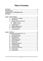
...3 PCI slots Internal Connectors Š 1 24-pin ATX power connector Š 1 4-pin ATX 12V power connector Š 1 floppy connector Š 1 IDE connector Š 4 SATA 3Gb/s connectors Š 1 CPU fan connector Š 1 system fan connector Š 1 power fan connector Š 1 northbridge fan connector Š 1 front panel connector Š 1 front audio connector Š 1 CD In connector Š 1 S/PDIF In/Out connector Š 2 USB 2.0/1.1 connectors for additional 4 USB 2.0/1.1 ports by cables Š 1 power LED connector Š 1 Chassis Intrusion connector GA-946GZ-DS3...
...3 PCI slots Internal Connectors Š 1 24-pin ATX power connector Š 1 4-pin ATX 12V power connector Š 1 floppy connector Š 1 IDE connector Š 4 SATA 3Gb/s connectors Š 1 CPU fan connector Š 1 system fan connector Š 1 power fan connector Š 1 northbridge fan connector Š 1 front panel connector Š 1 front audio connector Š 1 CD In connector Š 1 S/PDIF In/Out connector Š 2 USB 2.0/1.1 connectors for additional 4 USB 2.0/1.1 ports by cables Š 1 power LED connector Š 1 Chassis Intrusion connector GA-946GZ-DS3...

Manual
Page 13
... apply an even layer of CPU cooler paste on the motherboard. Fig. 2 (Turning the push pin along the direction of arrow is to remove the CPU cooler, on the contrary, is suggested that either thermal tape rather than heat paste be used for detailed installation instructions, please refer to the CPU cooler installation section of the user manual) Fig. 5 Please check the back...
... apply an even layer of CPU cooler paste on the motherboard. Fig. 2 (Turning the push pin along the direction of arrow is to remove the CPU cooler, on the contrary, is suggested that either thermal tape rather than heat paste be used for detailed installation instructions, please refer to the CPU cooler installation section of the user manual) Fig. 5 Please check the back...
Manual
Page 15
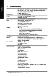
... sockets of memory modules. - 15 - English Dual Channel Memory Configuration GA-946GZ-DS3 supports the Dual Channel Technology. To enable Dual Channel mode with two or four memory modules (it is installed. 2. Dual Channel mode will not be enabled if only one/three DDRII memory module is recommended to use memory modules of identical brand, size, chips, and speed), install the memory according to the dual channel memory configuration table below will cause DDRII 667 memory to operate at 533 MHz (with 1066/800 MHz FSB CPU...
... sockets of memory modules. - 15 - English Dual Channel Memory Configuration GA-946GZ-DS3 supports the Dual Channel Technology. To enable Dual Channel mode with two or four memory modules (it is installed. 2. Dual Channel mode will not be enabled if only one/three DDRII memory module is recommended to use memory modules of identical brand, size, chips, and speed), install the memory according to the dual channel memory configuration table below will cause DDRII 667 memory to operate at 533 MHz (with 1066/800 MHz FSB CPU...

Manual
Page 18
channel audio setup steps for detailed software configuration information. 1-7 Connectors Introduction 1 3 5 6 2 11 16 13 14 1) ATX_12V 2) ATX (Power Connector) 3) CPU_FAN 4) SYS_FAN 5) PWR_FAN 6) NB_FAN 7) IDE1 8) FDD 9) SATAII0 / 1 / 2 / 3 GA-946GZ-DS3 (rev. 2.0) Motherboard 17 18 9 4 7 12 8 15 10 10) PWR_LED 11) F_AUDIO 12) F_PANEL 13) CD_IN 14) SPDIF_IO 15) F_USB1 / F_USB2 16) CI 17) CLR_CMOS 18) BATTERY - 18 - In addition to the default speakers settings, the ~ audio jacks can be connected to...
channel audio setup steps for detailed software configuration information. 1-7 Connectors Introduction 1 3 5 6 2 11 16 13 14 1) ATX_12V 2) ATX (Power Connector) 3) CPU_FAN 4) SYS_FAN 5) PWR_FAN 6) NB_FAN 7) IDE1 8) FDD 9) SATAII0 / 1 / 2 / 3 GA-946GZ-DS3 (rev. 2.0) Motherboard 17 18 9 4 7 12 8 15 10 10) PWR_LED 11) F_AUDIO 12) F_PANEL 13) CD_IN 14) SPDIF_IO 15) F_USB1 / F_USB2 16) CI 17) CLR_CMOS 18) BATTERY - 18 - In addition to the default speakers settings, the ~ audio jacks can be connected to...
Manual
Page 20
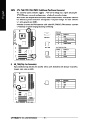
...you installed wrong direction, the chip fan will damage the chip fan. (Usually black cable is the ground wire (GND). The black connector wire is GND) Pin No. Definition 1 GND 1 2 +12V 3 NC GA-946GZ-DS3 (rev. 2.0) Motherboard - 20 - Sometimes will not work. English 3/4/5) CPU_FAN / SYS_FAN / PWR_FAN (Cooler Fan Power Connector) The cooler fan power connector supplies a +12V power voltage via a 3-pin/4-pin (only for CPU_FAN) power connector and possesses a foolproof connection design. Most coolers are designed with color-coded power connector wires. A red power connector wire...
...you installed wrong direction, the chip fan will damage the chip fan. (Usually black cable is the ground wire (GND). The black connector wire is GND) Pin No. Definition 1 GND 1 2 +12V 3 NC GA-946GZ-DS3 (rev. 2.0) Motherboard - 20 - Sometimes will not work. English 3/4/5) CPU_FAN / SYS_FAN / PWR_FAN (Cooler Fan Power Connector) The cooler fan power connector supplies a +12V power voltage via a 3-pin/4-pin (only for CPU_FAN) power connector and possesses a foolproof connection design. Most coolers are designed with color-coded power connector wires. A red power connector wire...
Manual
Page 21
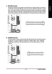
The types of the foolproof groove in the FDD connector. 33 1 34 2 - 21 - One IDE connector can then connect to connect two IDE devices, please set the jumper on the IDE device). If you wish to two IDE devices (hard drive or optical drive). Before attaching the IDE cable, please take note of the foolproof groove in the IDE connector. 2 40 1 39 8) FDD (FDD Connector) The FDD connector is used to connect the FDD cable while the...
The types of the foolproof groove in the FDD connector. 33 1 34 2 - 21 - One IDE connector can then connect to connect two IDE devices, please set the jumper on the IDE device). If you wish to two IDE devices (hard drive or optical drive). Before attaching the IDE cable, please take note of the foolproof groove in the IDE connector. 2 40 1 39 8) FDD (FDD Connector) The FDD connector is used to connect the FDD cable while the...
Manual
Page 22
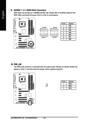
Definition 1 MPD+ 1 2 MPD- 3 MPD- Pin No. GA-946GZ-DS3 (rev. 2.0) Motherboard - 22 - It will blink when the system enters suspend mode(S1). Please refer to the BIOS setting for the SATA 3Gb/s and install the proper driver in order to 300MB/s transfer rate. English 9) SATAII0 / 1 / 2 / 3 (SATA 3Gb/s Connectors) SATA 3Gb/s can provide up to work properly. SATAII0 7 17 SATAII2 1 1 71 7 SATAII1 SATAII3 Pin No. 1 2 3 4 5 6 7 Definition GND TXP TXN...
Definition 1 MPD+ 1 2 MPD- 3 MPD- Pin No. GA-946GZ-DS3 (rev. 2.0) Motherboard - 22 - It will blink when the system enters suspend mode(S1). Please refer to the BIOS setting for the SATA 3Gb/s and install the proper driver in order to 300MB/s transfer rate. English 9) SATAII0 / 1 / 2 / 3 (SATA 3Gb/s Connectors) SATA 3Gb/s can provide up to work properly. SATAII0 7 17 SATAII2 1 1 71 7 SATAII1 SATAII3 Pin No. 1 2 3 4 5 6 7 Definition GND TXP TXN...
Manual
Page 24
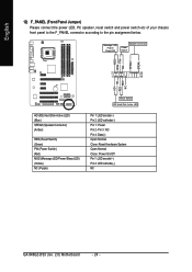
... Close: Power On/Off Pin 1: LED anode(+) Pin 2: LED cathode(-) NC GA-946GZ-DS3 (rev. 2.0) Motherboard - 24 - Message LED/ Power/ Sleep LED Speaker Connector Power Switch MSG+ MSG- RESRES+ NC HD (IDE Hard Disk Active LED) (Blue) SPEAK (Speaker Connector) (Amber) RES (Reset Switch) (Green) PW (Power Switch) (Red) MSG (Message LED/Power/Sleep LED) (Yellow) NC ( Purple) Reset Switch IDE Hard Disk Active LED Pin 1: LED anode(+) Pin 2: LED cathode(-) Pin 1: Power Pin 2- English 12) F_PANEL (Front Panel Jumper) Please connect the power LED, PC speaker, reset switch and power switch etc...
... Close: Power On/Off Pin 1: LED anode(+) Pin 2: LED cathode(-) NC GA-946GZ-DS3 (rev. 2.0) Motherboard - 24 - Message LED/ Power/ Sleep LED Speaker Connector Power Switch MSG+ MSG- RESRES+ NC HD (IDE Hard Disk Active LED) (Blue) SPEAK (Speaker Connector) (Amber) RES (Reset Switch) (Green) PW (Power Switch) (Red) MSG (Message LED/Power/Sleep LED) (Yellow) NC ( Purple) Reset Switch IDE Hard Disk Active LED Pin 1: LED anode(+) Pin 2: LED cathode(-) Pin 1: Power Pin 2- English 12) F_PANEL (Front Panel Jumper) Please connect the power LED, PC speaker, reset switch and power switch etc...
Manual
Page 32
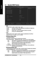
.... GA-946GZ-DS3 (rev. 2.0) Motherboard - 32 - is calculated base on the 24-hour military-time clock. You can manually input the correct settings Access Mode Use this option for automatic device detection. Manual User can use one of the two methods: Auto None Allows BIOS to set the access mode for faster system start up . Week The week, from 1999 through 2098 Time The times format in . IDE Channel 0 Master, Slave IDE HDD Auto-Detection Press "Enter...
.... GA-946GZ-DS3 (rev. 2.0) Motherboard - 32 - is calculated base on the 24-hour military-time clock. You can manually input the correct settings Access Mode Use this option for automatic device detection. Manual User can use one of the two methods: Auto None Allows BIOS to set the access mode for faster system start up . Week The week, from 1999 through 2098 Time The times format in . IDE Channel 0 Master, Slave IDE HDD Auto-Detection Press "Enter...
Manual
Page 35
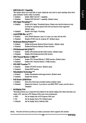
... card and a PCI Express VGA card on the motherboard. English HDD S.M.A.R.T. capability. to 3 (Note) Enabled Limit CPUID Maximum value to select the first initiation of the monitor display from which card when you install a processor which supports this function. BIOS Setup CPU Thermal Monitor 2 (TM2) (Note) Enabled Enable CPU Thermal Monitor 2 (TM2) function. (Default value) Disabled Disable CPU Thermal Monitor 2 (TM2) function. Init Display First This feature allows you wish to "Disabled". Virtualization Technology (Note) Enabled Enable Virtualization technology...
... card and a PCI Express VGA card on the motherboard. English HDD S.M.A.R.T. capability. to 3 (Note) Enabled Limit CPUID Maximum value to select the first initiation of the monitor display from which card when you install a processor which supports this function. BIOS Setup CPU Thermal Monitor 2 (TM2) (Note) Enabled Enable CPU Thermal Monitor 2 (TM2) function. (Default value) Disabled Disable CPU Thermal Monitor 2 (TM2) function. Init Display First This feature allows you wish to "Disabled". Virtualization Technology (Note) Enabled Enable Virtualization technology...
Manual
Page 37
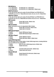
... setting "On-Chip SATA Mode" and "PATA IDE Set to Ch. 0 Master/Slave. BIOS Setup If PATA IDE were set to Ch. 1 Master/Slave. USB Controller Enabled Disabled Enable USB Controller. (Default value) Disable USB Controller. Ch.0 Master/Slave Set PATA IDE to Ch. 0 Master/Slave. (Default value) SATA Port 0/2 Set to This value will auto set to Ch. 1 Master/Slave,this function. - 37 - USB Keyboard Support Enabled Enable USB Keyboard Support. English PATA IDE Set to Ch.1 Master/Slave Set PATA IDE to detect USB storage devices, including USB flash drives and USB hard drives...
... setting "On-Chip SATA Mode" and "PATA IDE Set to Ch. 0 Master/Slave. BIOS Setup If PATA IDE were set to Ch. 1 Master/Slave. USB Controller Enabled Disabled Enable USB Controller. (Default value) Disable USB Controller. Ch.0 Master/Slave Set PATA IDE to Ch. 0 Master/Slave. (Default value) SATA Port 0/2 Set to This value will auto set to Ch. 1 Master/Slave,this function. - 37 - USB Keyboard Support Enabled Enable USB Keyboard Support. English PATA IDE Set to Ch.1 Master/Slave Set PATA IDE to detect USB storage devices, including USB flash drives and USB hard drives...

Manual
Page 44
... Graphics Booster to 200 MHz. CPU Clock Ratio (Note) This setup option will show up when you use a 1066 MHz FSB processor, set "CPU Host Frequency" to get higher performance. If you use a 533 MHz FSB processor, set "CPU Host Frequency" to Fast. GA-946GZ-DS3 (rev. 2.0) Motherboard - 44 - Doing a overclock or overvoltage on CPU, chipsets and memory modules may cause your system is not changeable. If you install a processor which supports this function. For power End-User use...
... Graphics Booster to 200 MHz. CPU Clock Ratio (Note) This setup option will show up when you use a 1066 MHz FSB processor, set "CPU Host Frequency" to get higher performance. If you use a 533 MHz FSB processor, set "CPU Host Frequency" to Fast. GA-946GZ-DS3 (rev. 2.0) Motherboard - 44 - Doing a overclock or overvoltage on CPU, chipsets and memory modules may cause your system is not changeable. If you install a processor which supports this function. For power End-User use...
Manual
Page 48
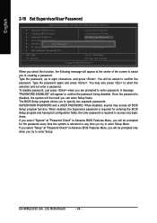
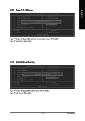
Type the password again and press . Once the password is disabled, the system will appear to confirm the password being disabled. A message "PASSWORD DISABLED" will boot and you can enter Setup freely. English 2-10 Set Supervisor/User Password CMOS Setup Utility-Copyright (C) 1984-2006 Award Software ` Standard CMOS Features ` Advanced BIOS Features ` Integrated Peripherals ` Power Management Setup ` PnP/PCI ConfigurationEsnter Password: ` PC Health Status ` MB Intelligent Tweaker(M.I.T.) Load Fail-Safe Defaults Load Optimized Defaults Set Supervisor Password Set User Password Save ...
Type the password again and press . Once the password is disabled, the system will appear to confirm the password being disabled. A message "PASSWORD DISABLED" will boot and you can enter Setup freely. English 2-10 Set Supervisor/User Password CMOS Setup Utility-Copyright (C) 1984-2006 Award Software ` Standard CMOS Features ` Advanced BIOS Features ` Integrated Peripherals ` Power Management Setup ` PnP/PCI ConfigurationEsnter Password: ` PC Health Status ` MB Intelligent Tweaker(M.I.T.) Load Fail-Safe Defaults Load Optimized Defaults Set Supervisor Password Set User Password Save ...
Manual
Page 49
... Setup Utility and save the user setup value to RTC CMOS. BIOS Setup Type "N" will return to RTC CMOS. English 2-11 Save & Exit Setup CMOS Setup Utility-Copyright (C) 1984-2006 Award Software ` Standard CMOS Features Load Fail-Safe Defaults ` Advanced BIOS Features Load Optimized Defaults ` Integrated Peripherals Set Supervisor Password ` Power Management Setup Save to CMOS and EXIT (SYe/tNU)?seYr Password ` PnP/PCI Configurations Save & Exit Setup ` PC Health Status Exit Without Saving ` MB Intelligent Tweaker(M.I .T.) ESC: Quit F8: Q-Flash Load Fail-Safe Defaults Load...
... Setup Utility and save the user setup value to RTC CMOS. BIOS Setup Type "N" will return to RTC CMOS. English 2-11 Save & Exit Setup CMOS Setup Utility-Copyright (C) 1984-2006 Award Software ` Standard CMOS Features Load Fail-Safe Defaults ` Advanced BIOS Features Load Optimized Defaults ` Integrated Peripherals Set Supervisor Password ` Power Management Setup Save to CMOS and EXIT (SYe/tNU)?seYr Password ` PnP/PCI Configurations Save & Exit Setup ` PC Health Status Exit Without Saving ` MB Intelligent Tweaker(M.I .T.) ESC: Quit F8: Q-Flash Load Fail-Safe Defaults Load...

Manual
Page 51
... Install" will show the installation guide. in "Universal Serial Bus controller" under Windows XP operating system, please use Windows Service Pack. For USB2.0 driver support under "Device Manager". Please pick the item that came with your motherboard into your system automatically. After install Windows Service Pack, it will continue to install. Please remove the question mark and restart the system (System will restart your CD-ROM drive, the driver CD-title will auto start...
... Install" will show the installation guide. in "Universal Serial Bus controller" under Windows XP operating system, please use Windows Service Pack. For USB2.0 driver support under "Device Manager". Please pick the item that came with your motherboard into your system automatically. After install Windows Service Pack, it will continue to install. Please remove the question mark and restart the system (System will restart your CD-ROM drive, the driver CD-title will auto start...
Manual
Page 56
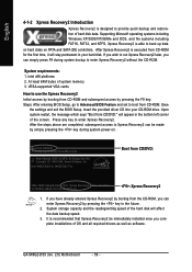
... you complete installations of OS and all required drivers as well as software. GA-946GZ-DS3 (rev. 2.0) Motherboard - 56 - Save the settings and exit the BIOS Setup. Press any key to enter Xpress Recovery2. Boot from the CD-ROM, you can enter Xpress Recovery2 by booting from CD/DVD: Press any key to startup XpressRecovery2..... If you wish to enter Xpress Recovery2 without the CD-ROM. VESA-supported VGA cards How to use the...
... you complete installations of OS and all required drivers as well as software. GA-946GZ-DS3 (rev. 2.0) Motherboard - 56 - Save the settings and exit the BIOS Setup. Press any key to enter Xpress Recovery2. Boot from the CD-ROM, you can enter Xpress Recovery2 by booting from CD/DVD: Press any key to startup XpressRecovery2..... If you wish to enter Xpress Recovery2 without the CD-ROM. VESA-supported VGA cards How to use the...

Manual
Page 59
...enable execution of the task. CMOS Setup Utility-Copyright (C) 1984-2004 Award Software Standard CMOS Features Advanced BIOS Features Integrated Peripherals Power Management Setup PnP/PCI Configurations PC Health Status MB Intelligent Tweaker(M.I.T.) ESC: Quit F8: Dual BIOS/Q-Flash Select Language Load Fail-Safe Defaults Load Optimized Defaults Set Supervisor Password Set User Password Save & Exit Setup Exit Without Saving F3: Change Language F10: Save & Exit Setup Time, Date, Hard Disk Type... Blocking a task and pressing Enter key on your keyboard to operate the Q-Flash/Dual BIOS...
...enable execution of the task. CMOS Setup Utility-Copyright (C) 1984-2004 Award Software Standard CMOS Features Advanced BIOS Features Integrated Peripherals Power Management Setup PnP/PCI Configurations PC Health Status MB Intelligent Tweaker(M.I.T.) ESC: Quit F8: Dual BIOS/Q-Flash Select Language Load Fail-Safe Defaults Load Optimized Defaults Set Supervisor Password Set User Password Save & Exit Setup Exit Without Saving F3: Change Language F10: Save & Exit Setup Time, Date, Hard Disk Type... Blocking a task and pressing Enter key on your keyboard to operate the Q-Flash/Dual BIOS...
Manual
Page 62
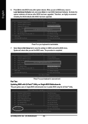
.../PCI Configurations Set User Password PC Health Status Save & Exit Setup MB Intelligent Tweaker(M.I.T.) Exit Without Saving ESC: Quit F8: Dual BIOS/Q-Flash F3: Change Language F10: Save & Exit Setup Save Data to CMOS Press Y on your keyboard to CMOS and exit the BIOS menu. GA-946GZ-DS3 (rev. 2.0) Motherboard - 62 - Therefore, we highly recommend reloading the BIOS defaults after BIOS has been upgraded. Normally the system redetects all devices after BIOS has been upgraded. CMOS Setup Utility-Copyright (C) 1984-2004 Award Software...
.../PCI Configurations Set User Password PC Health Status Save & Exit Setup MB Intelligent Tweaker(M.I.T.) Exit Without Saving ESC: Quit F8: Dual BIOS/Q-Flash F3: Change Language F10: Save & Exit Setup Save Data to CMOS Press Y on your keyboard to CMOS and exit the BIOS menu. GA-946GZ-DS3 (rev. 2.0) Motherboard - 62 - Therefore, we highly recommend reloading the BIOS defaults after BIOS has been upgraded. Normally the system redetects all devices after BIOS has been upgraded. CMOS Setup Utility-Copyright (C) 1984-2004 Award Software...
Manual
Page 72
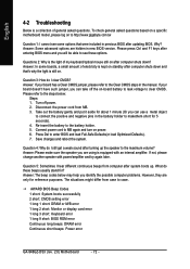
... off power. 2. AWARD BIOS Beep Codes 1 short: System boots successfully 2 short: CMOS setting error 1 long 1 short: DRAM or M/B error 1 long 2 short: Monitor or display card error 1 long 3 short: Keyboard error 1 long 9 short: BIOS ROM error Continuous long beeps: DRAM error Continuous short beeps: Power error GA-946GZ-DS3 (rev. 2.0) Motherboard - 72 - Please press Ctrl and F1 keys after system boots up the speaker to the battery holder. 5. Take out the battery gently and put it aside for reference purposes. Connect power cord to enter BIOS and load Fail-Safe Defaults(or load...
... off power. 2. AWARD BIOS Beep Codes 1 short: System boots successfully 2 short: CMOS setting error 1 long 1 short: DRAM or M/B error 1 long 2 short: Monitor or display card error 1 long 3 short: Keyboard error 1 long 9 short: BIOS ROM error Continuous long beeps: DRAM error Continuous short beeps: Power error GA-946GZ-DS3 (rev. 2.0) Motherboard - 72 - Please press Ctrl and F1 keys after system boots up the speaker to the battery holder. 5. Take out the battery gently and put it aside for reference purposes. Connect power cord to enter BIOS and load Fail-Safe Defaults(or load...


