Manual
Page 1
GA-945PLM-(D)S2 Intel® CoreTM 2 Extreme dual-core / CoreTM 2 Duo / Intel® Pentium® D / Pentium® 4 / Celeron® D LGA775 Processor Motherboard User's Manual Rev. 3001 12ME-945PLMDR-3001R * The WEEE marking on the product indicates this product must not be disposed of with user's other household waste and must be handed over to a designated collection point for the recycling of waste electrical and electronic equipment!! * The WEEE marking applies only in European Union's member states.
GA-945PLM-(D)S2 Intel® CoreTM 2 Extreme dual-core / CoreTM 2 Duo / Intel® Pentium® D / Pentium® 4 / Celeron® D LGA775 Processor Motherboard User's Manual Rev. 3001 12ME-945PLMDR-3001R * The WEEE marking on the product indicates this product must not be disposed of with user's other household waste and must be handed over to a designated collection point for the recycling of waste electrical and electronic equipment!! * The WEEE marking applies only in European Union's member states.
Manual
Page 2
Motherboard GA-945PLM-DS2/GA-945PLM-S2 Jan. 31, 2007 Motherboard GA-945PLM-DS2/ GA-945PLM-S2 Jan. 31, 2007
Motherboard GA-945PLM-DS2/GA-945PLM-S2 Jan. 31, 2007 Motherboard GA-945PLM-DS2/ GA-945PLM-S2 Jan. 31, 2007
Manual
Page 4
Table of Contents ItemChecklist ...6 OptionalAccessories ...6 GA-945PLM-DS2/GA-945PLM-S2 Motherboard Layout 7 Block Diagram ...8 Chapter 1 Hardware Installation 9 1-1 Considerations Prior to Installation 9 1-2 Feature Summary 10 1-3 Installation of the...14 1-5 Installation of Expansion Cards 16 1-6 I/O Back Panel Introduction 17 1-7 Connectors Introduction 18 Chapter 2 BIOS Setup 29 The Main Menu (For example:GA-945PLM-DS2 BIOS Ver. : F2a 30 2-1 Standard CMOS Features 32 2-2 Advanced BIOS Features 34 2-3 IntegratedPeripherals 36 2-4 Power Management Setup 40 2-5 PnP/PCI ...
Table of Contents ItemChecklist ...6 OptionalAccessories ...6 GA-945PLM-DS2/GA-945PLM-S2 Motherboard Layout 7 Block Diagram ...8 Chapter 1 Hardware Installation 9 1-1 Considerations Prior to Installation 9 1-2 Feature Summary 10 1-3 Installation of the...14 1-5 Installation of Expansion Cards 16 1-6 I/O Back Panel Introduction 17 1-7 Connectors Introduction 18 Chapter 2 BIOS Setup 29 The Main Menu (For example:GA-945PLM-DS2 BIOS Ver. : F2a 30 2-1 Standard CMOS Features 32 2-2 Advanced BIOS Features 34 2-3 IntegratedPeripherals 36 2-4 Power Management Setup 40 2-5 PnP/PCI ...
Manual
Page 7
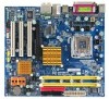
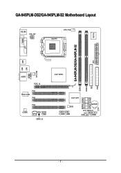
GA-945PLM-DS2/GA-945PLM-S2 Motherboard Layout IT8718 KB_MS ATX_12V CPU_FAN LGA775 COMA LPT GA-945PLM-DS2/GA-945PLM-S2 DDRII1 DDRII2 IDE ATX FDD USB LAN USB SYS_FAN F_AUDIO AUDIO PCIE_16 PCI1 RTL8110SC PCI2 PCI3 CODEC CD_IN COMB SPDIF_IO Intel® 945PL SATAII0 SATAII2 SATAII1 SATAII3 Intel® ICH7 BIOS F_USB1 F_USB2 BATTERY CLR_CMOS CI PWR_LED F_PANEL - 7 -
GA-945PLM-DS2/GA-945PLM-S2 Motherboard Layout IT8718 KB_MS ATX_12V CPU_FAN LGA775 COMA LPT GA-945PLM-DS2/GA-945PLM-S2 DDRII1 DDRII2 IDE ATX FDD USB LAN USB SYS_FAN F_AUDIO AUDIO PCIE_16 PCI1 RTL8110SC PCI2 PCI3 CODEC CD_IN COMB SPDIF_IO Intel® 945PL SATAII0 SATAII2 SATAII1 SATAII3 Intel® ICH7 BIOS F_USB1 F_USB2 BATTERY CLR_CMOS CI PWR_LED F_PANEL - 7 -
Manual
Page 10
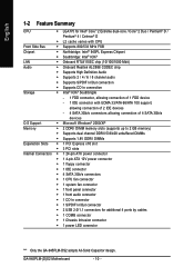
GA-945PLM-(D)S2 Motherboard - 10 - English 1-2 Feature Summary CPU Š LGA775 for Intel® CoreTM 2 Extreme dual-core / CoreTM 2 Duo / Pentium® D / Pentium® 4 / Celeron® D Š L2 ...; 1 S/PDIF In/Out connector Š 2 USB 2.0/1.1 connectors for additional 4 ports by cables Š 1 COMB connector Š 1 Chassis Intrusion connector Š 1 power LED connector "*" Only the GA-945PLM-DS2 adopts All-Solid Capacitor design.
GA-945PLM-(D)S2 Motherboard - 10 - English 1-2 Feature Summary CPU Š LGA775 for Intel® CoreTM 2 Extreme dual-core / CoreTM 2 Duo / Pentium® D / Pentium® 4 / Celeron® D Š L2 ...; 1 S/PDIF In/Out connector Š 2 USB 2.0/1.1 connectors for additional 4 ports by cables Š 1 COMB connector Š 1 Chassis Intrusion connector Š 1 power LED connector "*" Only the GA-945PLM-DS2 adopts All-Solid Capacitor design.
Manual
Page 12
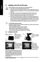
... that supports HT Technology and has it into its original position. Fig. 2 Remove the plastic covering on the CPU prior to the CPU during installation.) GA-945PLM-(D)S2 Motherboard - 12 -
... that supports HT Technology and has it into its original position. Fig. 2 Remove the plastic covering on the CPU prior to the CPU during installation.) GA-945PLM-(D)S2 Motherboard - 12 -
Manual
Page 14
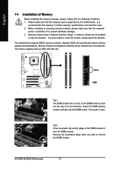
Insert the DIMM memory module vertically into the DIMM socket. Then push it down. GA-945PLM-(D)S2 Motherboard - 14 - The motherboard supports DDRII memory modules, whereby BIOS will automatically detect memory capacity and specifications. Notch DDRII Fig.1 The DIMM socket has a notch, ...
Insert the DIMM memory module vertically into the DIMM socket. Then push it down. GA-945PLM-(D)S2 Motherboard - 14 - The motherboard supports DDRII memory modules, whereby BIOS will automatically detect memory capacity and specifications. Notch DDRII Fig.1 The DIMM socket has a notch, ...

Manual
Page 15
..., please note the following explanations: 1. Dual Channel mode will double. To enable Dual Channel mode, please insert two DDRII memory modules (it is installed. 2. The GA-945PLM-DS2/GA-945PLM-S2 includes 2 DIMM sockets. Hardware Installation English Dual Channel Memory Configuration The GA-945PLM-DS2/GA-945PLM-S2 supports the Dual Channel Technology.
..., please note the following explanations: 1. Dual Channel mode will double. To enable Dual Channel mode, please insert two DDRII memory modules (it is installed. 2. The GA-945PLM-DS2/GA-945PLM-S2 includes 2 DIMM sockets. Hardware Installation English Dual Channel Memory Configuration The GA-945PLM-DS2/GA-945PLM-S2 supports the Dual Channel Technology.
Manual
Page 16
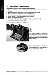
..., setup BIOS utility of expansion card from the slot. Power on the card are indeed seated in the slot. 5. Install related driver from the computer. 3. GA-945PLM-(D)S2 Motherboard - 16 - Read the related expansion card's instruction document before install the expansion card into expansion slot in the slot and does not rock. Replace...
..., setup BIOS utility of expansion card from the slot. Power on the card are indeed seated in the slot. 5. Install related driver from the computer. 3. GA-945PLM-(D)S2 Motherboard - 16 - Read the related expansion card's instruction document before install the expansion card into expansion slot in the slot and does not rock. Replace...

Manual
Page 18
... 6) IDE 7) SATAII0 / 1 / 2 / 3 8) PWR_LED 9) BATTERY 5 6 7 9 17 14 16 8 10 10) F_PANEL 11) F_AUDIO 12) CD_IN 13) SPDIF_IO 14) F_USB1 / F_USB2 15) COMB 16) CLR_CMOS 17) CI GA-945PLM-(D)S2 Motherboard - 18 - Only microphones still MUST be connected to perform different functions via the audio software. Stereo speakers, earphone or front surround speakers can be...
... 6) IDE 7) SATAII0 / 1 / 2 / 3 8) PWR_LED 9) BATTERY 5 6 7 9 17 14 16 8 10 10) F_PANEL 11) F_AUDIO 12) CD_IN 13) SPDIF_IO 14) F_USB1 / F_USB2 15) COMB 16) CLR_CMOS 17) CI GA-945PLM-(D)S2 Motherboard - 18 - Only microphones still MUST be connected to perform different functions via the audio software. Stereo speakers, earphone or front surround speakers can be...

Manual
Page 20
... +12V Sense 5) FDD (Floppy Connector) The FDD connector is the ground wire (GND). The types of the foolproof groove in the FDD connector. 34 33 2 1 GA-945PLM-(D)S2 Motherboard - 20 - Most coolers are : 360 KB, 720 KB, 1.2 MB, 1.44 MB and 2.88 MB.
... +12V Sense 5) FDD (Floppy Connector) The FDD connector is the ground wire (GND). The types of the foolproof groove in the FDD connector. 34 33 2 1 GA-945PLM-(D)S2 Motherboard - 20 - Most coolers are : 360 KB, 720 KB, 1.2 MB, 1.44 MB and 2.88 MB.

Manual
Page 22
Pin No. Definition 1 MPD+ 1 2 MPD- 3 MPD- 9) BATTERY GA-945PLM-(D)S2 Motherboard Danger of used batteries according to make them short for about one minute. (Or you want to erase CMOS... 1. Turn off . Gently take out ...
Pin No. Definition 1 MPD+ 1 2 MPD- 3 MPD- 9) BATTERY GA-945PLM-(D)S2 Motherboard Danger of used batteries according to make them short for about one minute. (Or you want to erase CMOS... 1. Turn off . Gently take out ...
Manual
Page 24
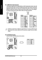
... module. English 11) F_AUDIO (Front Audio Connector) This connector supports either HD (High Definition) or AC97 front panel audio module. Definition 1 CD-L 2 GND 1 3 GND 4 CD-R GA-945PLM-(D)S2 Motherboard - 24 - Check the pin assignments carefully while you wish to use the front audio function, connect the front panel audio module to this connector...
... module. English 11) F_AUDIO (Front Audio Connector) This connector supports either HD (High Definition) or AC97 front panel audio module. Definition 1 CD-L 2 GND 1 3 GND 4 CD-R GA-945PLM-(D)S2 Motherboard - 24 - Check the pin assignments carefully while you wish to use the front audio function, connect the front panel audio module to this connector...
Manual
Page 26
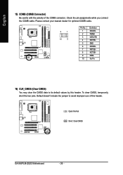
Check the pin assignments while you connect the COMB cable. Open: Normal Short: Clear CMOS GA-945PLM-(D)S2 Motherboard - 26 - Please contact your nearest dealer for optional COMB cable. 9 1 10 2 Pin No. 1 2 3 4 5 6 7 8 9 10 Definition NDCDBNSINB NSOUTB NDTRBGND NDSRBNRTSBNCTSBNRIBNo Pin 16) CLR_CMOS (Clear CMOS) ...
Check the pin assignments while you connect the COMB cable. Open: Normal Short: Clear CMOS GA-945PLM-(D)S2 Motherboard - 26 - Please contact your nearest dealer for optional COMB cable. 9 1 10 2 Pin No. 1 2 3 4 5 6 7 8 9 10 Definition NDCDBNSINB NSOUTB NDTRBGND NDSRBNRTSBNCTSBNRIBNo Pin 16) CLR_CMOS (Clear CMOS) ...
Manual
Page 28
English GA-945PLM-(D)S2 Motherboard - 28 -
English GA-945PLM-(D)S2 Motherboard - 28 -
Manual
Page 30
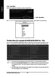
... BIOS Setup when somehow the system is not stable as figure below) will appear on cards) device. GA-945PLM-(D)S2 Motherboard - 30 - English : Boot Menu Select boot sequence for stability. 3. Press to exit this ...chapter are for reference only and may differ from the exact settings for 945PLM-DS2 F2a . . . . :BIOS Setup/Q-Flash :Xpress Recovery2 :Boot Menu :Qflash 12/27/2006-I945-6A79TG0CC-00 : Boot...ESC:Exit The Main Menu (For example:GA-945PLM-DS2 BIOS Ver. : F2a) Once you want, press "Ctrl+F1" to accept or enter the sub-menu...
... BIOS Setup when somehow the system is not stable as figure below) will appear on cards) device. GA-945PLM-(D)S2 Motherboard - 30 - English : Boot Menu Select boot sequence for stability. 3. Press to exit this ...chapter are for reference only and may differ from the exact settings for 945PLM-DS2 F2a . . . . :BIOS Setup/Q-Flash :Xpress Recovery2 :Boot Menu :Qflash 12/27/2006-I945-6A79TG0CC-00 : Boot...ESC:Exit The Main Menu (For example:GA-945PLM-DS2 BIOS Ver. : F2a) Once you want, press "Ctrl+F1" to accept or enter the sub-menu...

Manual
Page 32
... devices during POST(default) • None Select this option for automatic device detection. Access Mode Use this to Sat, determined by the BIOS and is , , , . GA-945PLM-(D)S2 Motherboard - 32 - The four options are used and the system will skip the automatic detection step and allow for faster system start up . time clock...
... devices during POST(default) • None Select this option for automatic device detection. Access Mode Use this to Sat, determined by the BIOS and is , , , . GA-945PLM-(D)S2 Motherboard - 32 - The four options are used and the system will skip the automatic detection step and allow for faster system start up . time clock...
Manual
Page 34
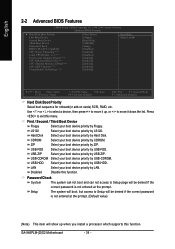
...-Threading (Note) Limit CPUID Max. LS120 Hard Disk Select your boot device priority by LS120. USB-HDD Select your boot device priority by USB-HDD. GA-945PLM-(D)S2 Motherboard - 34 -
...-Threading (Note) Limit CPUID Max. LS120 Hard Disk Select your boot device priority by LS120. USB-HDD Select your boot device priority by USB-HDD. GA-945PLM-(D)S2 Motherboard - 34 -
Manual
Page 36
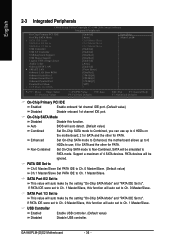
... This value will auto make by the setting "On-Chip SATA Mode" and "PATA IDE Set to". PATA devices will auto set to PATA mode. GA-945PLM-(D)S2 Motherboard - 36 - USB Controller Enabled Enable USB controller. (Default value) Disabled Disable USB controller. PATA IDE Set to Ch.0 Master/Slave Set PATA IDE to...
... This value will auto make by the setting "On-Chip SATA Mode" and "PATA IDE Set to". PATA devices will auto set to PATA mode. GA-945PLM-(D)S2 Motherboard - 36 - USB Controller Enabled Enable USB controller. (Default value) Disabled Disable USB controller. PATA IDE Set to Ch.0 Master/Slave Set PATA IDE to...
Manual
Page 38
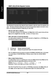
... problem occurs on the LAN cable connected to detect the status of wires, the Status field will show Open, and the length shown is activated. GA-945PLM-(D)S2 Motherboard - 38 - If no cable problem is detected on a specified pair of the attached LAN cable. Link Detected --> 100Mbps Cable Length= 30m Link Detected Cable...
... problem occurs on the LAN cable connected to detect the status of wires, the Status field will show Open, and the length shown is activated. GA-945PLM-(D)S2 Motherboard - 38 - If no cable problem is detected on a specified pair of the attached LAN cable. Link Detected --> 100Mbps Cable Length= 30m Link Detected Cable...


